TCP/IP Protocols and Devices
Abstract
In this chapter, you will learn more about the TCP/IP protocol stack and the tools used in this book to investigate the Illustrated Network. We’ll look at more details of TCP/IP and explore how TCP/IP devices provide internetworking from LAN to LAN.
You will learn about the types of devices used to connect LANs (such as bridges and routers) and conclude with the concept of VLANs and Metro Ethernet services.
Keywords
TCP/IP protocols; LANs; client–server model; bridges; routers; switches; Illustrated Network; VLANs
In this chapter, you will learn more about the TCP/IP protocol stack and the tools used in this book to investigate the Illustrated Network. We’ll look at more details of TCP/IP and explore how TCP/IP devices provide internetworking from LAN to LAN.
You will learn about the types of devices used to connect LANs (such as bridges and routers) and conclude with the concept of VLANs and Metro Ethernet services.
The LANs on the Illustrated Network, including the LAN in the home office, are connected using routers as the network nodes. Each LAN forms a discrete network by itself, with its own clients and servers. When previously separate LANs are connected, or a previously complete LAN is segmented, the result is often called an internetwork.
Routers can be used to build an internetwork of LANs, but this is not the only way. Routers operate at the packet layer (Layer 3 of the TCP/IP model), and LANs can be linked or segmented at other layers of a protocol stack as well. Some routers can also function at these other layers, as the routers on the Illustrated Network can (i.e., routers often include functions other than pure routing). However, in many cases, different devices are used to link and segment LANs, devices that are not really routers at all.
This chapter will take a closer look at the Illustrated Network in several areas. First, we’ll take a closer look at the individual layers and protocols that make up the TCP/IP protocol stack. Then, we’ll investigate how devices handle internetworking from LAN to LAN at each protocol layer. Finally, we’ll describe some other devices or methods that can be used between LANs, ending with a concept known as a virtual LAN or VLAN. VLANs are used by service providers to support a service known as Metropolitan Ethernet or Metro Ethernet.
Figure 2.1 shows the areas of the Illustrated Network we will be investigating in this chapter. The protocol stacks and layers run mainly on the host clients and servers, so the devices on the two LANs are shaded, along with the customer edge routers. We’ll also mention the Gigabit Ethernet links and a Metro Ethernet, so those are highlighted as well.
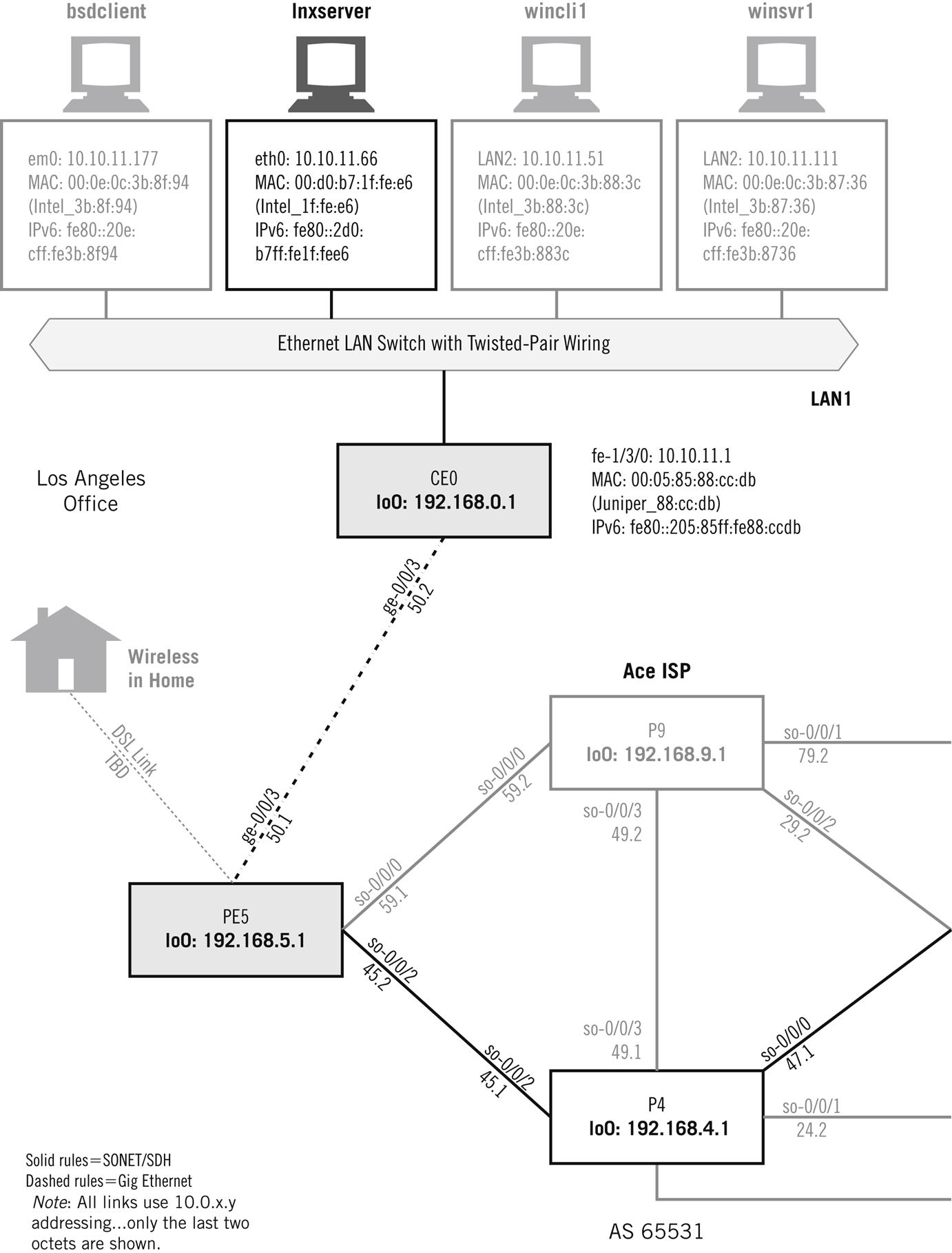
Each host in Figure 2.1 has three types of addresses associated with the interface connected to the LAN. The first is the IPv4 address. For example, the LAN interface on host lnxserver is eth0 and the IPv4 address is 10.10.11.66. The next address is the hardware address, or MAC address on a LAN: 00:d0:b7:1 f:fe:e6. Finally, each host lists the link-local IPv6 address based on this MAC address, or fe80::2d0:b7ff:fe1f:fee6 for lnxserver. We’ll talk more about IPv4 and IPv6 addressing and packets in Chapters 4 through 6.
Protocol Stacks on the Illustrated Network
LANs on the Illustrated Network send and receive frames, mainly Ethernet II frames. Inside the frames are the packets that flow from source to destination. The packets, and the messages inside the packets, are formatted according to the individual protocols that make up the TCP/IP protocol stack.
What major TCP/IP protocols are used on the Illustrated Network? Wireshark has a convenient summary screen that displays whenever Wireshark is capturing packets. Let’s run Wireshark on wincli2 and see what kind of protocols we capture when we remotely access router CE6 and find the IP address associated with winsrv1. The summary screen is shown in Figure 2.2. Note that the figures still shows the former name of “Ethereal,” but the output shows essentially the same information as the current version.
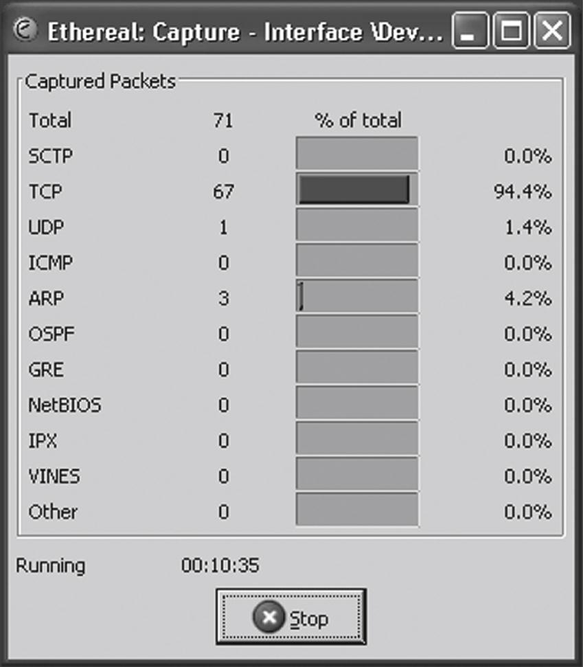
Most of the packets we have captured contain TCP. There are a couple from the User Datagram Protocol (UDP) and Address Resolution Protocol (ARP). The relationship between Ethernet II frames, IP packets, and these protocols is clearer when we look at the Wireshark protocol hierarchy statistics screen, as shown in Figure 2.3.
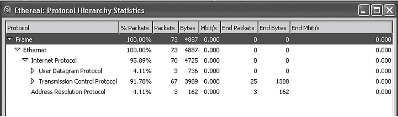
It is easy to see in the figure that all of the frames are Ethernet (II) frames, and that all but 3 of the 73 packets captured are IP packets. The 70 IP packets include 67 TCP packets and 3 UDP packets. We’ll explore more about how all of these protocols fit together in this chapter.
Layers, Protocols, Ports, and Sockets
We’ll take a closer look at frames in Chapter 3. For now, all we need to know is that layered protocols like TCP/IP function in a specific way. Frames are sent on LANs and inside the frame are packets. The packets carry the information from device to device. This information can be application data, but there are also packets that perform control and administrative tasks as well as data transfer.
Layering is not a magical solution to network protocol implementation. There is usually only one network interface on a host, so all applications must share this common interface, which has the network (IP) address. But how are arriving packets distributed to the proper application? The packets are all for this IP address, but which application layer process gets the information inside the packet?
The transport-layer protocol that should process the information inside the packet is indicated by the value in the protocol field of the IPv4 header. (We’ll talk about IPv4 now, and detail the fields in the IPv4 and IPv6 headers in a later chapter.)
Inside the transport layer data unit, the receiving application is indicated by the port number in the transport layer header (again, we’ll discuss these header fields in full in later chapters). By looking at the protocol and port fields, the TCP/IP stack at the destination knows which application gets the information. If two applications try to use the same port at the same time, this is an error condition.
Another important application layer concept in TCP/IP is the socket. A socket is the combination of the IP address and port number. We’ve already seen that this combination will uniquely identify an application. The socket is also the way that programmers often write networking application, using the socket as a kind of entry point to the other layers of the protocol stack. Often, sockets are built into the application programming interface (API).
An API is an important part of the application layer interface, but not all APIs are socket-based. Sockets are not even tied to the protocols themselves. Sockets and ports are important enough in TCP/IP to merit a detailed examination in a later chapter of this book. For now, we’ll just look where the port number is carried and how the socket identifier is determined.
How can we find the port and socket in an IP packet inside an Ethernet frame? Let’s use Wireshark to find them.
First, we’ll use a little “echo” client and server utility on the Linux hosts to generate the frames for this exercise. (Note: This “echo” utility is not the same as the /bin/echo program on Linux systems.) We can invoke the server on the lnxserver host and use the client to send a simple string to be echoed back by the server process. We’ll use Tethereal (the text version of Wireshark) this time, just to show that the same information is available in either the graphical or text-based version.
First, we’ll run the Echo server process, which normally runs on port 7, on port 55555. This will help us easily locate the data we are looking for in the Ethereal capture.
[root@lnxserver admin]# . /echo 55555
We have to run Tethereal on each end as well, if we want to compare frames. The command is the same on the client and server. We’ll use the verbose (–V) switch to see the MAC layer information as packets arrive.
[root@lnxclient admin]# /usr/sbin/tethereal –V
Capturing on eth0
Now we can invoke the Echo client to bounce the string TESTING123 off the server process.
[root@lnxclient admin]# . /echo 10.10.11.66 TESTING123 55555
Received: TESTING123
[root@lnxclient admin]#
What did we get? Let’s look at the frames leaving the client. We only need to examine the information pertaining to the port and socket. Only one of the frames captured is shown.
[root@lnxclient admin]# /usr/sbin/tethereal –V
Capturing on eth0
…
Frame 4 (52 bytes on wire, 52 bytes captured)
Arrival Time: May 16, 2008 13:32:59.702046000
Time delta from previous packet: 57.243134000 seconds
Time relative to first packet: 62.239970000 seconds
Frame Number: 4
Packet Length: 52 bytes
Capture Length: 52 bytes
Ethernet II, Src: 00:b0:d0:45:34:64, Dst: 00:05:85:8b:bc:db
Destination: 00:05:85:8b:bc:db (Juniper__8b:bc:db)
Source: 00:b0:d0:45:34:64 (Dell_45:34:64)
Type: IP (0x0800)
Internet Protocol, Src Addr: 10.10.12.166 (10.10.12.166), Dst Addr: 10.10.11.66
(10.10.11.66)
Version: 4
Header length: 20 bytes
Differentiated Services Field: 0x00 (DSCP 0x00: Default; ECN: 0x00)
0000 00.. = Differentiated Services Codepoint: Default (0x00)
.... ..0. = ECN-Capable Transport (ECT): 0
.... ...0 = ECN-CE: 0
Total Length: 38
Identification: 0x0000
Flags: 0x04
.1.. = Don't fragment: Set
..0. = More fragments: Not set
Fragment offset: 0
Time to live: 64
Protocol: UDP (0x11)
Header checksum: 0x0ecc (correct)
Source: 10.10.12.166 (10.10.12.166)
Destination: 10.10.11.66 (10.10.11.66)
User Datagram Protocol, Src Port: 32825 (32825), Dst Port: 55555 (55555)
Source port: 32825 (32825)
Destination port: 55555 (55555)
Length: 18
Checksum: 0x1045 (correct)
Data (10 bytes)
0000 54 45 53 54 49 4e 47 31 32 33 TESTING123
Let’s look at the fields that are emphasized. First, we have captured an Ethernet II frame with an IPv4 packet inside. The frame’s type field value of 0x800 determines this. In the IP packet, the message from the client to the server, which starts on the next line, the source address is 10.10.12.166 (lnxclient) and the destination address is 10.10.11.66 (lnxserver), as they should be.
We can ignore the rest of the IP header fields for now, and skip down to where the source and destination port are highlighted. The source port chosen by the client is 32825 and the port on the server that will receive the data is 55555. We decided that 55555 would be the server port, and the client chose a port number to use based on certain rules, which we will talk about in a later chapter.
Now that we know the IP addresses and ports used, we can determine the socket at each host. This is shown in Table 2.1.
The TCP/IP Protocol Stack
The layering of TCP/IP is important if IP packets are to run on almost any type of network. The IP packet layer is only one layer, and from the TCP/IP perspective, the layer or layers below the IP layer are not as important as the overall flow of packets from one host (end system) to another across the network.
Layering means that you only have to adapt one type of packet to an underlying network type to get the entire TCP/IP suite. Once the packet has been “framed,” you need not worry about TCP/UDP, or any other protocol: they come along for the ride with the layering. Only the IP layer has to deal with the underlying hardware.
All that really matters is that the device at the receiving end understands the type of IP packet encapsulation used at the sending end. If only one form of packet encapsulation was used, the IP packets could remain inside the frame with a globally unique MAC address from source to destination. Network nodes could forward the frame without having to deal with the packet inside. We’ll talk more about the differences between forwarding frames and forwarding packets later on in this book.
TCP/IP is considered to be a peer protocol stack, which means that every implementation of TCP/IP is considered to have the same capabilities as every other. There are no “restricted” or “master” versions of TCP/IP that anyone need be concerned about. So, for example, there is no special server stack needed.
However, this does not mean that all protocol stacks function in precisely the same way. TCP/IP, like many other protocol stacks, is implemented according to a model known as the client–server model.
The Client–Server Model
The hosts that run TCP/IP usually fall into one of two major categories: The host could be client or the host could be a server. However, this is mostly an application-layer model issue because most computers are fully multitasking-capable today. It is possible that the same host could be running the client version of a program for one application (e.g., the Web browser) and the server version of another program (e.g., a file transfer server) at the same time. Dedicated servers are most common on the Internet, but almost all client computers can act as servers for a variety of applications. The details are not as important as the interplay among layers and applications.
TCP/IP Layers and Client–Server
TCP/IP has five layers. The bottom layers are the physical layer and underlying network layer. The underlying network technologies at the network layer are the topic of the next chapter. Above the data link layer is the IP layer itself. The IP layer forms and routes the IP packet (also called a datagram in a lot of documentation) and IP is the major protocol at this layer.
The transport layer of TCP/IP consists of two major protocols: The Transmission Control Protocol (TCP) and the User Datagram Protocol (UDP). TCP is a reliable layer added on top of the best-effort IP layer to make sure that even if packets are lost in transit, the hosts will be able to detect and resend missing information. TCP data units are called segments. UDP is as best-effort as IP itself, and UDP data units are called datagrams. The messages that applications exchange are made up of strings of segments or datagrams. Segments and datagrams are used to chop up application content, such as huge, multimegabyte files, into more easily handled pieces.
TCP is reliable in the sense that TCP always resends corrupt or lost segments. This strategy has many implications for delay-sensitive applications such as voice or video.
TCP is a connection-oriented layer on top of the connectionless IP layer. This means that before any TCP segment can be sent to another host, a TCP connection must be established to that host. Connectionless IP has no concept of a connection, and simply forwards packets without any understanding if the packets ever really got where they were going.
In contrast to TCP, UDP is a connectionless transport layer on top of connectionless IP. UDP segments are simply forwarded to a destination under the assumption that sooner or later a response will come back from the remote host. The response forms an implied or formal acknowledgment that the UDP segment arrived.
At the top of the TCP/IP stack is the application, or application services, layer. This is where the client–server concept comes into play. The applications themselves typically come in client or server versions, which is not true at other layers of TCP/IP. While a host computer might be able to run client processes and server processes at the same time, in the simplest case, these processes are two different applications.
Client–server application implementation can be extremely simple. A server process can start and basically sit and “listen” for clients to “talk” to the server. For example, a Web server is brought up on a host successfully whether there is a browser client pointed at it or not. The Web server process issues a passive open to TCP/IP and essentially remains idle on the network side until some client requests content. However, the Web browser (the client) process issues an active open to TCP/IP and attempts to send packets to a Web site immediately. If the Web site is not reachable, that causes an error condition.
To sum up the simplest application cases: Clients talk and servers listen (and usually reply). It is very easy to program an application that either talks or listens, although TCP/IP specifications allow for the transition of passive and active open from one state to another. We’ll talk more about client and server application and passive and active opens in the chapter on sockets.
A more detailed look at the TCP/IP protocol stack is shown in Figure 2.4. The TCP/IP stack bridges the gap between interface connector on the network side (hardware) and the memory address space of the application on the host (software).
The names of the protocol data units used at each layer are worth reviewing. The unit of the network layer is the frame. Inside the frame is the data unit of the IP layer, the packet. The unit of the transport layer is the segment in TCP and datagram in UDP. The segment or datagram by definition is the content of the information-bearing packet. Finally, applications exchange messages. Segments and datagrams taken together form the messages that the applications are sending to each other.
This is a good place to explore some of the operational aspects of the TCP/IP protocol stack above the network access (or data link) layer.
The IP Layer
The connectionless IP layer routes the IP packets independently through the collection of network nodes such as routers that make up the “internetwork” that connects the LANs. Packets at the IP layer do not follow “paths” or “virtual circuits” or anything else set up by signaled or manually defined connections for packet flow in other types of network layers. However, this also means that the packets’ content might arrive out of sequence, or even with gaps in the sequence due to lost packets, at the destination.
IP does not care to which application a packet belongs. IP delivers all packets without a sense of priority or sensitivity to loss. The whole point of IP is to get packets from one network interface to another. IP itself is not concerned with the lack of guaranteed quality of service (QoS) parameters such as bandwidth availability or minimal delay, and this is characteristic of all connectionless, best-effort networks. Even the basics, such as sequenced delivery of packet content, priorities, and guaranteed delivery in the form of acknowledgments (if these are needed by the application), must be provided by the higher layers of the TCP/IP protocol stack. These reliable transport functions are not functions of the IP layer, and some are not even functions of TCP.
Two other major protocols run at the IP layer besides IPv4 or IPv6 (or both). The routers that form the network nodes in a TCP/IP network must be able to send error messages to the hosts if a router must discard a packet (e.g., due to lack of buffer space because of congestion). This protocol is known as the Internet Control Message Protocol (ICMP). ICMP messages are sent inside IP packets, but ICMP is still considered a different protocol and not a separate layer.
The other major protocol placed at the IP layer has many different functions depending on the type of network that IP is running on. This is the Address Resolution Protocol (ARP). The main function of ARP is to provide a method for IPv4, which technically knows only about packets, to find out the proper network layer address to place in the frame header destination field. On LANs, this is the MAC address. Without this address, the network beneath the IP layer could not deliver the frame containing the IP packet to the proper destination. (IPv6 does not use ARP: IPv6 uses multicast for this purpose.)
On a LAN, ARP is a way for IPv4 to send a broadcast message onto the LAN asking, in effect, “Who has IP address 192.168.13.84?” Each system, whether host or router, on the LAN will examine the ARP message (all systems must pay attention to a broadcast) and the system having the IP address in question will reply to the sender’s MAC address found in the source field of the frame. This target system will also cache the IP address information so that it knows the MAC address of the sender (this cuts down on ARP traffic on the network). The MAC layer address needed by the sending system is found in the source address field of the frame carrying the ARP reply packet.
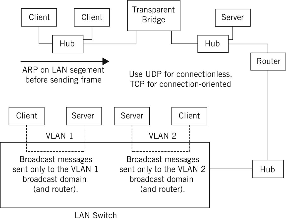
ARP messages are broadcast to every host in what is called the network layer broadcast domain. The broadcast domain can be a single physical group (e.g., all hosts attached to a single group of hubs) or a logical grouping of hosts forming a virtual LAN (VLAN). More will be said about broadcast domains and VLANs later in this chapter.
The Transport Layer
The two main protocols that run above the IP layer at the transport layer are TCP and UDP. Lately, UDP has been assuming more and more prominence on the Internet, especially with applications such as voice and multicast traffic such as video. One reason is that TCP, with its reliable resending, is not particularly well suited for real-time applications (real time just means that the network delays must be low and stable or else the application will not function properly). For these applications, late-arriving data are worse than data that do not arrive at all, especially if the late data cause all the data “behind” it to also arrive late. (Of course, in spite of these limitations, TCP is still used for some audio streaming and similar applications).
Transmission Control Protocol
TCP’s built-in reliability features include sequence numbering with resending, which is used to detect and resend missing or out-of-sequence segments. TCP also includes a complete flow control mechanism (called windowing) to prevent any sender from overwhelming a receiver. Neither of these built-in TCP features is good for real-time audio and video on the Internet. These applications cannot “pause” and wait for missing segments, nor should they slow down or speed up as traffic loads vary on the Internet. (The fact that they do just points out the incomplete nature of TCP/IP when it comes to quality of service for these applications and services).
TCP contains all the functions and mechanisms needed to make up for the best-effort connectionless delivery provided by the IP layer. Packets could arrive at a host with errors, out of their correct sequence, duplicated, or with gaps in sequence due to lost (or discarded) packets. TCP must guarantee that the data stream is delivered to the destination application error-free, with all data in sequence and complete. Following the practice used in connection-oriented networks, TCP uses acknowledgments that periodically flow from the destination to the source to assure the sender that all is well with the data received to that point in time.
On the sending side, TCP passes segments to the IP layer for encapsulation in packets, which the IP layer in hosts and routers route connectionlessly to the destination host. On the receiving side, TCP accepts the incoming segments from the IP layer and delivers the data they represent to the proper application running above TCP in the exact order in which the data were sent.
User Datagram Protocol
The TCP/IP transport layer has another major protocol. UDP is as connectionless as IP. When applications use UDP instead of TCP, there is no need to establish, maintain, or tear down a connection between a source and destination before sending data. Connection management adds overhead and some initial delay to the network. UDP is a way to send data quickly and simply. However, UDP offers none of the reliability services that TCP does. UDP applications cannot rely on TCP to ensure error-free, guaranteed (via acknowledgments), in-sequence delivery of data to the destination.
For some simple applications, purely connectionless data delivery is good enough. Single request–response message pairs between applications are sent more efficiently with UDP because there is no need to exchange a flurry of initial TCP segments to establish a connection. Many applications will not be satisfied with this mode of operation, however, because it puts the burden of reliability on the application itself.
UDP is often used for short transactions that fit into one datagram and packet. Real-time applications often use UDP with another header inside called the real-time transport protocol (RTP). RTP borrows what it needs from the TCP header, such as a sequence number to detect (but not to resend) missing packets of audio and video, and uses these desirable features in UDP.
The Application Layer
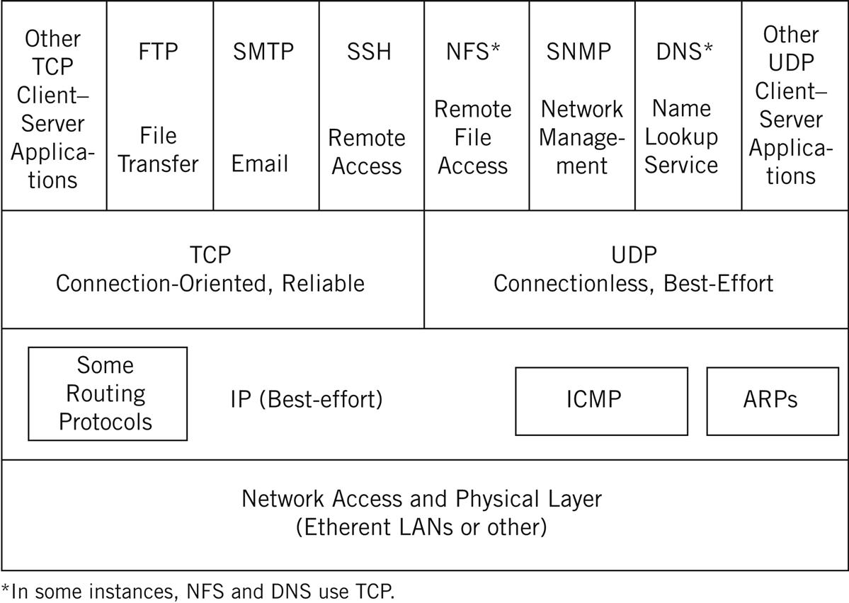
At the top of the TCP/IP protocol stack, at the application layer, are the basic applications and services of the TCP/IP architecture. Several basic applications are typically bundled with the TCP/IP software distributed from various sources and, fortunately, are generally interoperable.
The standard application services suite usually includes a file transfer method (File Transfer Protocol: FTP), a remote terminal access method (Telnet, which is not commonly used today, and others, which are), an electronic mail system (Simple Mail Transfer Protocol: SMTP), and a Domain Name System (DNS) resolver for domain name to IP address translation (and vice versa), and more. Many TCP/IP implementations also include a way of accessing files remotely (rather than transferring the whole file to the other host) known as the Network File System (NFS). There is also the Simple Network Management Protocol (SNMP) for network operations. For the Web, the server and browser applications are based on the Hypertext Transfer Protocol (HTTP). Some of these applications are defined to run on TCP and others are defined to run on UDP, and in many cases can run on either.
Bridges, Routers, and Switches
The TCP/IP protocol stack establishes an architecture for internetworking. These protocols can be used to connect LANs in the same building, on a campus, or around the world. Not all internetworking devices are the same. Generally, network architects seeking to extend the reach of a LAN can choose from one of four major interconnection devices: repeaters, bridges, routers, and switches.
Not long ago, the network configuration and the available devices determined which type of internetworking device should be used. Today, network configurations are growing more and more complex, and the devices available often combine the features of several of these devices. For example, the routers on the Illustrated Network have all the features of traditional routers, plus some switching capabilities.
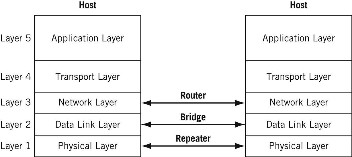
In their simplest forms, repeaters, bridges, and routers operate at different layers of the TCP/IP protocol stack, as shown in Figure 2.5. Roughly, repeaters forward bits from one LAN segment to another, bridges forward frames, and routers forward packets. Switches are important enough to deserve a separate discussion at the end of this section.
This section will explore the major characteristics of internetworking with bridges, routers, and switches. It will show how the LAN collision and broadcast domains are defined. This section will also show how the IP layer in particular and other protocols in TCP/IP interact in a routing environment.
Segmenting LANs
Network administrators and designers are often faced with a need to increase the amount of bandwidth available to users, increase the number of users supported, or extend the coverage of a LAN. The good news is that this means that the network is popular and useful, but the bad news is that there are lots of ways that these goals can be accomplished, some better than others.
Sometimes the answer is relatively straightforward. If a 100-Mbps Fast Ethernet is congested, moving everyone to Gigabit Ethernet will provide an instant increase in bandwidth (close to the theoretical tenfold increase with lots of tuning). However, this also usually means replacing adapter cards and replacing the “hubs” to support the new bandwidth and frames. This type of wholesale upgrade can be very expensive.
Another way to give each user more bandwidth (and at the same time increase users and coverage) is to segment the LAN. Segmenting does not require replacing all of the user equipment. As the name implies, segmenting breaks the LAN into smaller portions and then reconnects them with an internetworking device.
Another consequence of the different protocol layers at which the various internetworking devices function is the number of LAN collision and broadcast domains created. Ethernet’s CSMA/CD access method can result in collisions when stations on the LAN try to send at almost the same time. Collisions “waste” bandwidth because they destroy the frames, and the colliding stations must wait and try to send again. (Actually, unless they are oversubscribed, CSMA/CD systems offer better performance than token-passing or other methods.) Even when Ethernets do not generate collisions, broadcast frames must be examined by each receiver because the destination address cannot be used to determine interest in content. Bandwidth is wasted if broadcast frames are sent to systems that have no interest in the content of the broadcast message. (In TCP/IP, ARPs are the major type of broadcast frames that systems send and receive).
It should be noted that although CSMA/CD is part of Gigabit Ethernet, it is essentially nonexistent and not present at all in 10-Gigabit Ethernet.
Extending a LAN by forward bits still creates a single collision and broadcast domain. The number of collision and broadcast domains created by all the internetworking devices discussed is shown in Table 2.2. We’ll look at why this is true of each device in detail shortly.
Table 2.2
Collision and Broadcast Domains
| Internetwork Device | Collision Domains | Broadcast Domains |
| Repeater | One | One |
| Bridge | Many | One |
| Router | Many | Many |
| Switch | Many | Depends on VLAN configuration |
The use of these devices is not mutually exclusive. In other words, a router can be used to segment a LAN into two (or more) segments, and each resulting segment can be divided further with bridges. In an extreme case, each individual user or system has the full media bandwidth available. This is what switches can do.
Repeaters are a type of special case in that they do not segment a LAN at all. Repeaters do not furnish more bandwidth for users; they just extend the reach of the LAN. Repeaters are included in the table as a “baseline” for comparison. Repeaters forward bits from one segment to another and have no intelligence with regard to data format. If the frame contains errors, violates rules about minimum or maximum frame sizes, or anything else is wrong, the repeaters forward the frame anyway.
Note that wireless LAN devices connected to an attachment point share the same properties as a repeater network. And repeaters, technically obsolete on wired networks, have renewed life on wireless networks, especially what are called “ad hoc” wireless networks.
A 100BaseT Ethernet LAN consists of at least one multiport repeater (often called a “hub”) with twisted-pair wires connected directly to each system. All systems see all frames, for better or worse. There are strict limits to the size to which a network made up of repeater-connected LAN segments can grow. The more systems there are that can send, the less of the total shared bandwidth each system has. Ethernet limits the number of systems that each LAN segment can have (the number varies by specific Ethernet type). Finally, there are distance limits to the electrical signals that repeaters propagate.
Bridges
Ethernet specifications limit the number of systems on a LAN segment and the overall distance spanned. To add devices to a LAN that has reached the maximum in one or both of these categories, a bridge can be used to connect LAN segments. Bridged networks normally filter frames and do not forward all frames onto all segments connected to the bridge. This is why bridges create more than one collision domain. However, the LAN segments linked by the bridge still normally form one broadcast domain. Although the word “bridge” is often applied to products, pure bridges are at least as obsolete as hubs.
The filtering process employed by a bridge differs according to specific LAN technology. Ether net uses transparent bridging to connect LAN segments. A transparent bridge looks at the destination MAC address to decide if the frames should be:
• Forwarded—The frame is sent only onto the LAN segment where the destination is located. The bridge examines the source MAC address fields to find specific device locations.
• Filtered—The frame is dropped by the bridge. No message is sent back to the source.
• Flooded—The frame is sent to every LAN segment attached to the bridge. This is done for broadcast and multicast traffic.
When bridges are used to connect LAN segments, the media bandwidth is shared only by the devices on each segment. Because the broadcast domain is preserved, the bridged LANs still function as one big LAN. Bridges also discard frames with errors, as well as frames that violate LAN protocol length rules, and thus protect the other LAN segments when things go wrong.
Bridges are certainly an improvement over repeaters, but still have a number of issues. The common ARPs used to associate IP addresses at Layer 3 with LAN MAC addresses at Layer 2 pass through all bridges, but broadcasts due to protocols are not usually the issue. However, multicast traffic is also flooded, and multimedia applications such as videoconferences can easily overwhelm a bridged network. Some issues are more mundane: printers, which generate very little traffic, sometimes remain invisible in a bridged network.
Ethernet bridges must also be spanning tree bridges. These bridges can detect loops in the interconnected topology of LAN segments and bridges. Loops are a problem in bridged networks because some frames are always flooded onto all segments. Flooding multiplies the total number of frames on the network. Loops multiply frames over and over until a saturation point is reached and the LAN ceases to function.
Routers
Bridges add functions to an interconnected LAN because they operate at a higher layer of the protocol stack than repeaters. Bridges run at Layer 2, the frame layer, and can do everything a repeater can do, and more, because bridges create more collision domains. In the same way, routers add functionality to bridges and operate at Layer 3, the packet layer. Routers not only create more collision domains, they create more LAN broadcast domains as well.
In a LAN with repeaters or bridges, all of the systems belong to the same subnet or subnetwork. Layer 3 addresses in their simplest form—and IP addresses are a good example of this—consist of a network and system (host) portion of the address. LANs connected by routers have multiple broadcast domains, and each LAN segment belongs to a different subnetwork.
Because of the presence of multiple subnets, TCP/IP devices must behave differently in the presence of a router. Bridges connecting TCP/IP hosts are transparent to the systems, but routers connecting hosts are not. At the very least, the host must know the address of at least one router, the default router, to send packets beyond the local subnet. As we’ll soon see, use of the default router requires the use of a default route, a route that matches all IPv4/IPv6 packets.
Bridges are sometimes called “protocol independent” devices, which really means that bridges can be used to connect LAN segments regardless of whether TCP/IP is used or not. However, routers must have Layer 3 software to handle whichever Layer 3 protocols are in use on the LAN. Many routers, especially routers that connect to the Internet, can and do understand only the IP protocol. However, many routers can handle multiple Layer 3 protocols, including protocols that are not usually employed with routed networks.
LAN Switches
The term “switch” in networking has threatened to become as overused as “hub.” When applied to LANs, a switch is still a device with a number of common characteristics that can be compared to bridges and routers.
The LAN switch is really a complex bridge with many interfaces. LAN switching is the ultimate extension of multiport bridging. A LAN switch has every device on its own segment, giving each system the entire media bandwidth all for itself. Multiple systems can transmit simultaneously as long as there are no “port collisions” on the LAN switch. Port collisions occur when multiple source ports try to send a frame to the same output port at the same time.
All of the ports on the switch establish their own broadcast domain. However, when broadcast frames containing ARPs or multicast traffic arrive, the switch floods the frames to all other ports. Unfortunately, this makes LAN switching not much better than a repeater or a bridge when it comes to dealing with broadcast and multicast traffic (but there is an improvement because broadcast traffic cannot cause collisions that would force retransmissions).
To overcome this problem, a LAN switch can allow multiple ports to be assigned to a broadcast domain. The broadcast domains on a LAN switch are configurable and each floods broadcast and multicast traffic only within its own domain. As a matter of fact, it is not possible for any frames to cross the boundary of a broadcast domain: Another external device, such as a router, is always required to internetwork the domains.
When LAN switches define multiple broadcast domains they are creating virtual LANs (VLANs). Not all LAN switches can define VLANs, especially smaller ones, but many can. A VLAN defines membership to a LAN logically, through configuration, not physically by sharing media or devices. Today, VLANs are extended by use of virtual extensible LANs (VXLANs) and those are important enough to deserve a chapter considering their use in this book.
On a WAN, the term “switch” means a class of network nodes that behave very differently than routers. We’ll look more closely at how “fast packet network” devices, such as Frame Relay and ATM switches as network nodes, differ from routers in a later chapter. Although Frame Relay and ATM have limited deployment today, the ideas behind them are important. What fast packet technologies tried to accomplish is worth at least a brief look.
Virtual LANs
A VLAN, according to the official IEEE definition, defines broadcast domains at Layer 2. VLANs, as a Layer 2 entity, really have little to do with the TCP/IP protocol stack, but VLANs make a huge difference in how switches and routers operate on a TCP/IP network.
Routers do not propagate broadcasts as bridges do, so a router automatically defines broadcast domains on each interface. Layer 2 LAN switches logically create broadcast domains based on configuration of the switch. The configuration tells the LAN switch what to do with a broadcast received on a port in terms of what other ports should receive it (or if it should even be flooded to all other ports).
When LAN switches are used to connect LAN segments, the broadcast domains cannot be determined just by looking at the network diagram. Systems can belong to different, the same, or even multiple, broadcast domains. The configuration files in the LAN switches determine the boundaries of these domains as well as their members. Each broadcast domain is a type of “virtual bridge” within the switch. This is shown in Figure 2.6.
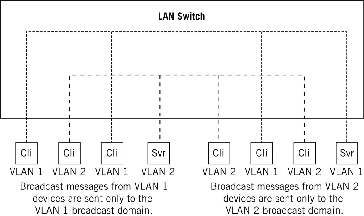
Each virtual bridge configured in the LAN switch establishes a distinct broadcast domain, or VLAN. Frames from one VLAN cannot pass directly to another VLAN on the LAN switch (or else you create one big VLAN or broadcast domain). Layer 3 internetworking devices such as routers must be used to connect the VLANs, allowing internetworking and at the same time keeping the VLAN broadcast domains distinct. All devices that can communicate directly without a router (or other Layer 3 or higher device) share the same broadcast domain.
VLAN Frame Tagging
VLAN devices can come in all shapes and sizes, and configuration of the broadcast domains can be just as variable. Interoperability of LAN switches is compromised when there are multiple ways for a device to recognize the boundaries of broadcast domains. To promote interoperability, the IEEE established IEEE 802.1Q to standardize the creation of VLANs through the use of frame tagging.
Some care is needed with this aspect of VLANs. VLANs are not really a formal networking concept, but they are a nice feature that devices can support. One key VLAN feature is the ability to place switch ports in virtual broadcast domains. The other key feature is the ability to tag Ethernet frames with a VLAN identifier so that devices can easily distinguish the boundaries of the broadcast domains. These devices and tags are not codependent, but you have to use both features to establish a useful VLAN.
In a later chapter, we'll see how the Virtual Extensible LAN (VXLAN) builds on the basic VLAN idea here.
Multiple tags can be placed inside Ethernet frames. There is also a way to assign priorities to the tagged frames, often called IEEE 802.1p, but officially known as IEEE 802.1D-1998. Internetworking devices, not just LAN switches, can read the tags and establish VLAN boundaries based on the tag information.
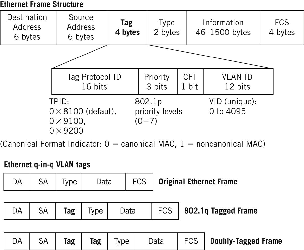
VLAN tags add 4 bytes of information between the Source Address and Type/Length fields of Ethernet frames. The maximum size of the modified Ethernet frame is increased from 1518 to 1522 bytes, so the frame check sequence must be recalculated when the VLAN tag is added. VLAN identifiers can range from 0 to 4095.
The use of VLAN “q in q” tags increases the available VLAN space (ISPs often assign each customer a VLAN identifier, and customers often have their own VLANs as well). In this case, multiple tags are placed in an Ethernet frame. The format and position of VLAN tags according to IEEE 802.3ac are shown in Figure 2.7.
VLANs are built for a variety of reasons. Among them are:
Security—Frames on an Ethernet segment are delivered everywhere, and devices only process (look inside) MAC frames that are addressed to them. Nothing stops a device from monitoring everything that arrives on the interface (that’s essentially how Ethereal works). Sensitive information, or departmental traffic, can be isolated with virtual LANs.
Cutting down on broadcasts—Some network protocols are much worse than others when it comes to broadcasts. These broadcast frames can be an issue because they rarely carry user data and each and every system on the segment must process the content of a broadcast frame. VLANs can isolate protocol broadcasts so that they arrive only at the systems that need to hear them. Also, a number of hosts that might otherwise make up a very large logical network (e.g., Page 19 what we will call later a “/19-sized wireless subnet”) could use VLANs because they can be just plain noisy.
Router delay—Older routers can be much slower than LAN switches. VLANs can be used to establish logical boundaries that do not need to employ a router to get traffic from one LAN segment to another. (In fairness, many routers today route at “wire speed” and do not introduce much latency into a network.)
The Illustrated Network uses Gigabit Ethernet links to connect the customer-edge routers to the ISP networks. Many ISPs would assign the frame arriving from LAN1 and LAN2 a VLAN ID and tag the frames at the provider-edge routers. If the sites are close enough, some form of Metro Ethernet could be configured using the tag information. However, the sites are far enough apart that we would have to use some other method to create a single LAN out of LAN1 and LAN2.
In a later chapter, we’ll use VLAN tagging, along with some other router switching features, to create a “virtual private LAN” between LAN1 and LAN2 on the Illustrated Network, mainly for security purposes. Then we’ll look at VXLANs in a chapter on Ethernet VPNs (EVPNs).
After that, we’ll use VXLAN as well.
Questions for Readers
Figure 2.8 shows some of the concepts discussed in this chapter and can be used to help you answer the following questions.
1. What is the main function of the ARP message on a LAN?
2. What is the difference between TCP and UDP terms of connection overhead and reliability?
3. What is a transparent bridge?
4. What is the difference between a bridge and a router in terms of broadcast domains?
5. What is the relationship between a broadcast domain and a VLAN?