IPv4 and IPv6 Addressing
Abstract
In this chapter, you will learn about the addressing used in IPv4 and IPv6. We’ll assign addresses of both types to various interfaces on the hosts and routers of the Illustrated Network. We’ll mention older classful IPv4 addressing and the current classless system. We will start to explore the differences between IPv4 and IPv6 addressing and why both exist.
You will learn about the important concept of subnetting and supernetting and other aspects of IP addressing. We’ll detail the IP subnet mask as well.
Keywords
IPv4 addressing; IPv6 addressing; subnet masking; CIDR
In this chapter, you will learn about the addressing used in IPv4 and IPv6. We’ll assign addresses of both types to various interfaces on the hosts and routers of the Illustrated Network. We’ll mention older classful IPv4 addressing and the current classless system. We will start to explore the differences between IPv4 and IPv6 addressing and why both exist.
You will learn about the important concept of subnetting and supernetting and other aspects of IP addressing. We’ll detail the IP subnet mask as well.
In many ways, IPv4 and IPv6 are distinct protocols with important differences. Nevertheless, both IPv4 and IPv6 are valid IP layer addresses, some networks use both IPv4 and IPv6, and the packet data content is the same in both. Network engineers often deal with both every day, and we will too. In the future, the importance of IPv6 will only grow.
IPv4 addressing was fairly straightforward to understand before the Internet exploded all over the world. Then the original (“classful”) rules for assigning networks IPv4 addresses didn’t work as well, and routers were getting overwhelmed by the size and resources needed to maintain routing and forwarding tables.
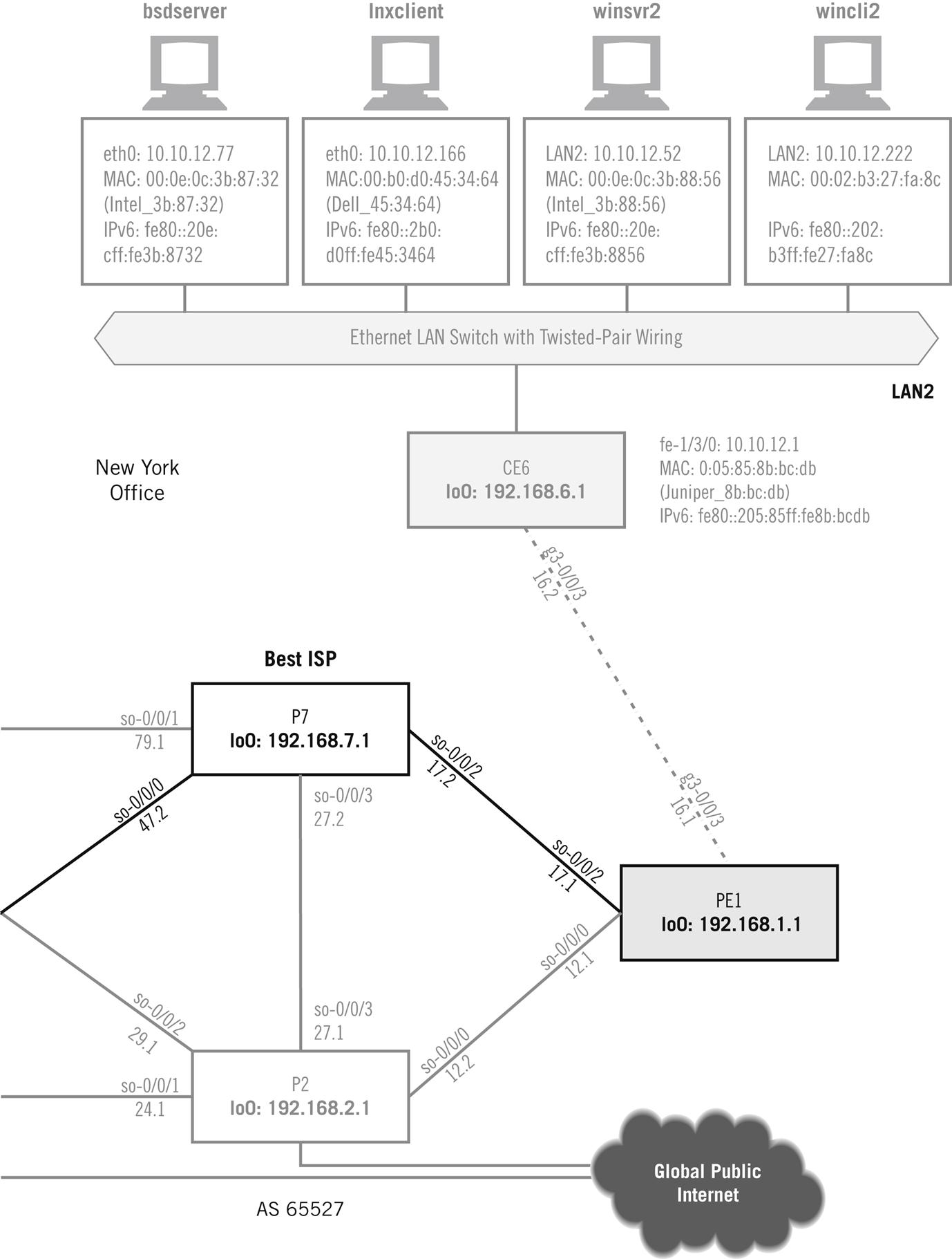
This chapter investigates both IPv4 and IPv6 addressing, and the host and router interfaces on the Illustrated Network have both IPv4 and IPv6 addresses (see Figure 5.1). We’ll assign these addresses manually in this chapter.

We’ll start the discussion by describing the classless Internet routing (CIDR) rules created so that we did not run out of IPv4 addresses in 1994, shortly after the Web exploded onto the scene. Then we’ll describe the older classful system, and, finally, we’ll talk about IPv6 addressing. This chapter also explores important aspects of IP addressing subnetting and supernetting.
IP Addressing
In Chapter 2 we worked a lot with the Linux and Windows clients and servers. Let’s start with our FreeBSD hosts and routers to look at IPv4 and IPv6 addresses on the device’s interfaces.
Figure 5.1 shows through shading the portion of the network we’ll be working with in this chapter. All of the ISP routers have IP addresses, of course, both IPv4 and IPv6, but we’ll only look at the addressing of the customer routers. Although it can be important, we won’t worry about the addressing used internally by service providers. The things that can go wrong there are far beyond this introductory discussion.
When the Illustrated Network was first configured, we manually assigned an IPv4 address to the bsdserver Ethernet interface (em0) with ifconfig. The only tricky part was translating the prefix length used on our network (/24) to a decimal network mask for this host (this was done only to show this common method). We could have used 10.10.12.77/24 as well, or even hex (0xffffff00). We’ll talk about prefix lengths and network masks later on in this chapter. The ifconfig command generates no output, but we can look at the result using ifconfig without any parameters.
bsdserver# ifconfig em0 inet 10.10.12.77 netmask 255.255.255.0
bsdserver# ifconfig
em0: flags=8843<UP,BROADCAST,RUNNING,SIMPLEX,MULTICAST> mtu 1500
options=3<RXCSUM,TXCSUM>
inet6 fe80::20e:cff:fe3b:8732%em0 prefixlen 64 scopeid 0x1
inet 10.10.12.77 netmask 0xffffff00 broadcast 10.10.12.255
ether 00:0e:0c:3b:87:32
media: Ethernet autoselect (100baseTX <full-duplex>)
status: active
The interface flags are interpreted on the first line of the output. Interface em0 is up and running, and can send or receive, but not at the same time (simplex). It can send and receive broadcasts and multicast, and has a Maximum Transmission Unit (MTU) of 1500 bytes (a normal Ethernet frame). If a packet is queued for output and is too large for this 1500-byte frame, then the packet content must be fragmented into multiple frames, each in its own packet. We’ll talk about fragmentation in detail in a later chapter. The option line says that the frame check sequence is generated when transmitting and checked when receiving.
Note that we got an IPv6 address (the inet6 line) as well. This is called the link-local (0xfe80) IPv6 address. It is based on the MAC address and generated automatically, with a prefix length (prefixlen) of /64. Newer versions of FreeBSD function this way, as long as the local router is properly configured to run IPv6. You can use the ifconfig command with the inet6 option to assign a specific IPv6 address to the interface. (There’s a lot more to IPv6 addressing, such as router-assigned prefixes, but we’re keeping it very basic here.)
The next line lists the IPv4 address, netmask, and the address used as an IP broadcast address to send packets to every device on the network. The MAC address has a line all its own, followed by the type of media: 100-Mbps, twisted-pair Ethernet, capable of sending and receiving (full-duplex) at the same time (but em0 will not do that). The interface is active as well as up, which means that it is sending and receiving bits.
Linux uses slightly different syntax to assign IPv4 addresses to interfaces. Let’s assign an IPv4 address to the lnxclient Ethernet interface (eth0) using ifconfig. In this case, the network mask format is easier to read. We’ll look at the interface before the address is assigned, and then after, and find something very different from FreeBSD with regard to the network broadcast address.
[root@lnxclient admin]# ifconfig
eth0 Link encap:Ethernet HWaddr 00:B0:D0:45:34:64
UP BROADCAST RUNNING MULTICAST MTU:1500 Metric:1
RX packets:43993 errors:0 dropped:0 overruns:1 frame:0
TX packets:0 errors:0 dropped:0 overruns:0 carrier:0
collisions:0 txqueuelen:100
RX bytes:7491082 (7.1 Mb) TX bytes:0 (0.0 b)
Interrupt:5 Base address:0xec00
[root@lnxclient admin]# ifconfig eth0 10.10.12.166 netmask 255.255.255.0
[root@lnxclient admin]# ifconfig
eth0 Link encap:Ethernet HWaddr 00:B0:D0:45:34:64
inet addr:10.10.12.166 Bcast:10.255.255.255 Mask:255.255.255.0
UP BROADCAST RUNNING MULTICAST MTU:1500 Metric:1
RX packets:44000 errors:0 dropped:0 overruns:1 frame:0
TX packets:0 errors:0 dropped:0 overruns:0 carrier:0
collisions:0 txqueuelen:100
RX bytes:7492614 (7.1 Mb) TX bytes:0 (0.0 b)
Interrupt:5 Base address:0xec00
This output gives much the same information as FreeBSD, but provides more details for traffic statistics and error conditions. The last line of output gives details about how the interface card communicates with the operating system and has nothing directly to do with the network. Note that no automatic IPv6 addresses are generated. All versions of the Linux kernel newer than 2.2, regardless of distribution, now support ways to give an interface an IPv6 address, but we will not do that.
However, Linux has also done something very odd with the broadcast address. We’ll talk more about broadcast address formats later in this chapter, but it is supposed to be formed by setting all of the host bits that follow the network bits in the IP address to 1. Now, we set a network mask for 24 bits (255.255.255.0), but Linux has set all the bits in the field to a string of 1 bits in the broadcast mask to the last 24 bits of the IPv4 address, or 10.255.255.255. As we saw with FreeBSD, the correct broadcast address for this network mask should be 10.10.12.255.
This means, as we’ll soon discover, that this older version of Linux expects classful IPv4 addresses, and today we mostly use classless IPv4 addresses. (There was some debate as to whether this was a “broken” version or install, but the behavior is consistent and all else seems well. I was going to update this behavior for this edition, but I decided to keep it to show how small things can have odd effects, and how some things might need fixing to work properly.)
To fix the broadcast address so that the network functions properly (yes, it matters), we’ll have to specify a broadcast address for lnxclient (and do the same for lnxserver).
[root@lnxclient admin]# ifconfig eth0 broadcast 10.10.12.255
[root@lnxclient admin]# ifconfig
eth0 Link encap:Ethernet HWaddr 00:B0:D0:45:34:64
inet addr:10.10.12.166 Bcast:10.10.12.255 Mask:255.255.255.0
UP BROADCAST RUNNING MULTICAST MTU:1500 Metric:1
RX packets:44000 errors:0 dropped:0 overruns:1 frame:0
TX packets:0 errors:0 dropped:0 overruns:0 carrier:0
collisions:0 txqueuelen:100
RX bytes:7492614 (7.1 Mb) TX bytes:0 (0.0 b)
Interrupt:5 Base address:0xec00
Let’s move on to the Windows devices. In Windows, you typically use the graphical interface to assign IPv4 addresses, subnet masks, and default gateways. The method is well-documented in many places and need not be detailed here. You can easily view the current IP addresses by running the Windows ipconfig command in the PowerShell. Here’s the result on wincli2.
Microsoft Windows PowerShell
(C) Copyright 2016 Microsoft Corporation. All rights reserved.
C:\Users\walterg>ipconfig
Windows IP Configuration
Ethernet adapter Local Area Connection:
Media State . . . . . . . . . . . . . : Media Disconnected
Connection-specific DNS Suffix . :
Wireless LAN Adapter Local Area Connection* 2:
Media State . . . . . . . . . . .. . . : Media Disconnected
Connection-specific DNS Suffix . :
Wireless LAN Adapter Local Area Connection* 3:
Media State . . . . . . . . . . .. . . : Media Disconnected
Connection-specific DNS Suffix . :
Wireless LAN Adapter wireless Network Connection:
Connection-specific DNS Suffix . . . .: Home Link-Local
IPv6 Address . . . . . . . . . . . . . : fe80::25be:2a5a:2bbf:f25e%5
IPv4 Address . . . . . . . . . .. . . : 10.10.12.222
Subnet Mask . . . . . . . . . . .. . . : 255.255.255.0
Default Gateway . . . . . . . . . . . : 10.10.12.1
Tunnel Adapter isatap.Home:
Media State . . . . . . . . . . .. . . : Media Disconnected
Connection-specific DNS Suffix . : Home
Tunnel adapter Teredo Tunneling Pseudo-Interface:
Connection-specific DNS Suffix . :
IPv6 Address. . . . . . . . . . . . : 2001:0:9d38:90d7:3c93:2507:b820:7732
Link-Local IPv6 Address . . . . : fe80::3c93:2507:b820:7732%12
Default Gateway . . . . . . . . . : ::
Unlike the Unix-based output, Windows associates a default gateway with the interface. This information is properly part of the host routing and forwarding routing table, and we’ll talk more about default gateways in a later chapter on routing.
The IPv6 address for the LAN interface is a site-local address based on the MAC address of the interface (see Chapter 3). The “%” number is just an index for the order in which certain types of IP addresses were generated.
On working networks, more than just the automatic tunnel IPv6 address is usually created. It is not unusual to see a Tunnel adapter Teredo Tunneling Pseudo-Interface. Teredo is a Microsoft initiative, defined in RFC 3904, that allows devices to reach the IPv6 Internet from behind a network address translation (NAT) device. There is often a Tunnel adapter 6to4 Tunneling Pseudo-Interface as well, depending on how the routers are configured. A full discussion of these Windows IPv6 interfaces is beyond the scope of this book, but we’ll discuss IPv6 tunneling in more detail in Chapter 9.
The customer edge routers are Juniper Networks routers. The configuration files on these routers look very different from those on a Cisco router. Juniper Networks router configurations are more like C language programs and are organized with braces in indented stanzas. However, Juniper Networks router configurations can be rendered in “set” language that looks more like Cisco’s style. For example, on router CE0, the addressing on interface fe-1/3/0 is more complex than on a host:
admin@CE0> show interface ge-1/3/0
unit 0 {
family inet {
address 10.10.11.1/24;
}
family inet6 {
address fc00:ffb3:d5:b:205:85ff:fe88:ccdb/64;
}
}
user@CE0>
In this format, all statements configured under another statement (indented) apply to that higher level statement. Thus, both family inet and family inet6 apply to unit 0, but only the address 10.10.11.1/24 applies to family inet. The form is used often in this book, and becomes more familiar with repetition.
This form can also be shown in the following more compact format, which is the style we will use in this book:
admin@CE0> set interface ge-1/3/0 unit 0 family inet address 10.10.11.1/24;
admin@CE0> set interface ge-1/3/0 unit 0 family inet6 address
fc00:ffb3:d5:b:205:85ff:fe88:ccdb/64;
This output is for logical unit 0, the simplest case. Juniper Networks router interfaces can have logical units numbered from 0 to 65535, and each can have more than one IPv4 or IPv6 address. The LAN interface on CE6 looks very much the same, except for the address specifics.
We’ll talk about the specifics of the IPv4 and IPv6 address formats, network marks, and prefix lengths, and other topics, in the rest of this chapter. At the end, we’ll see just what the complex IPv6 address format is telling us about the Illustrated Network.
One type of address we won’t be exploring in this chapter is the anycast address. To understand anycast addresses, consider that there are three major types of IP addresses.
Unicast—This type of IP address is used to identify a single network interface. It establishes a one-to-one relationship between the network address and network endpoint (interface). So each unicast address uniquely identifies a network source or destination.
Broadcast/Multicast—This type of IP address is used to identify a changeable group of interfaces. Broadcast addresses are used to send a message to every reachable interface, and broadcast domains are typically defined physically. Multicast addresses are not limited to a single domain and multicast groups are established logically. IPv6 relies on multicast addresses for many of the discovery features of IPv6 and things that are done with broadcasts in IPv4. In both multicast and broadcast, there is a many-to-one association between network address and network endpoints. Consequently, one address identifies a group of network endpoints, and information is replicated by routers to reach them all.
Anycast—This type of IP address, formally defined in IPv6, is used to identify a defined set of interfaces, usually on different devices. Anycast addresses are used to deliver packets to the “nearest” interface, where nearness is defined as a routing parameter. The same can be done in IPv4, but not as elegantly. However, multicasts deliver to many interface destinations, while anycasts deliver to only one, although many might be reachable. Anycasts are useful for redundancy purposes, so servers can exist around the world, all with the same address, but traffic is only sent to the one that is the “closest” to the source.
This book uses mainly unicast IP addresses. Multicast and anycast addresses will be introduced and used as necessary.
The Network/Host Boundary
We just saw that the mask determines where the boundary between the network and host portions of the IP address lies. This boundary is important: If it is set too far to the right, there are lots of networks, but none of them can have many hosts. If it is set too far to the left, then there are plenty of hosts allowed, but fewer networks overall.
In IP, the address boundary is moveable, and always has been. But in the past, right through the big Internet explosion in the mid-1990s, the network/host boundary in IPv4 could only be in one of three places. This produced lots of networks that were too small in terms of hosts, and many that were far too large, capable of holding millions of hosts. Not only that, but there were so many small networks, each of which needing a separate routing table entry in each and every core Internet router, that the Internet threatened to drown under its own weight.
In a nutshell, the inability to aggregate Class C blocks drove routing table pressure and the unsustainable rate of allocation of Class A and Class B addresses. This would have caused IPv4 exhaustion by 1994 to 1995, as projected in 1990.
So the rules were changed to allow the network/host boundary in IPv4 and IPv6 addresses to be set almost anywhere (there are still some basic rules). When applied to the former, fixed, IPv4 octet boundaries, if you moved the “natural” boundary of the mask to the right of its normal position, this was called subnetting and the address space gets smaller. (Actually, even the older “natural” IPv4 addresses could always be subnetted.) And if you moved the “natural” boundary of the mask to the left of its normal position, this was called supernetting and the address space became larger.
In this chapter, we will talk about subnetting and supernetting in detail. Supernetting is more commonly called “aggregation” today, but we’ll call it supernetting in this chapter just to make the contrast with subnetting explicit. We will also talk about the current system of rules for hosts and routers concerning the positioning of the boundary between the network and host portion of the IP address, variable-length subnet masking (VLSM), and classless interdomain routing (CIDR). But first, let’s look at the IPv4 address in detail.
The IPv4 Address
The IPv4 address is a network layer concept and has nothing to do with the addresses that the data link layer uses, often called the hardware address on LANs. IPv4 addresses must be mapped to LAN hardware addresses and WAN serial link addresses. However, there is no real relationship between LAN media access control (MAC) or WAN serial link addresses in the frame header and the IPv4 addresses used in the packet header, with the special exception of multicast addresses.
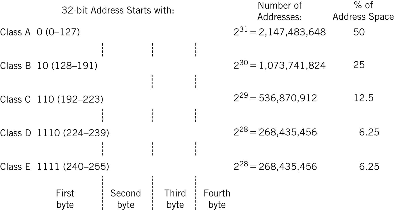
The original IPv4 addressing scheme established in RFC 791 is known as classful addressing. The 32 bits of the IPv4 address fall into one of several classes based on the value of the initial bits in the IPv4 address. The major classes used for addresses were A, B, and C. Class D was (and is) used for IPv4 multicast traffic, and Class E was “reserved” for experimental purposes. Each class differs in the number of IPv4 address bits assigned to the network and the host portion of the IP address. This scheme is shown in Figure 5.2.
Note that with Class A, B, and C, we are referring to the size of the blocks being allocated as well as the region from which they were allocated by IANA. However, Classes D and E refer to the whole respective region. Multicast addresses, when they were assigned for applications, for example, were assigned one at a time like (for instance) port numbers. (We’ll talk about port numbers in a later chapter.) In the rest of this chapter, references to Classes A, B, and C are concerned with address space sizes and not locations.
The 4 billion (actually 4,294,967,296) possible IPv4 addresses are split up into five classes. The five classes are not equal in size, and Class A covers a full half of the whole IPv4 address space. Class E addresses are “experimental” and some of them have been used for that purpose, but they are seldom seen today.
In practice, only the Class D addresses are still used on the Internet in a classful manner. Class D addresses are the IPv4 multicast addresses (224.0.0.0 to 239.255.255.255), and we’ll talk about those as needed. We will nonetheless talk about classful IPv4 addressing in this book, especially later on in this chapter when subnetting is considered and when mentioning the routing protocol RIPv1. However, the significance of classful IPv4 addressing is strictly historical. Classful addressing comes up occasionally, and at least some introduction is necessary.
This chapter, and this book, emphasizes classless IP addresses, the current way of interpreting the 32-bit IPv4 address space. This scheme assumes that no classes exist and is how routers on the Internet interpret IPv4 addresses. In classless addressing, the IPv4 network mask or prefix determines the boundary between the network and host portion of the IP address instead of the initial IP address bits. On a host, it is still often called a network mask, because hosts don’t care about classful or classless, but it is called a prefix on a router.
Hosts really don’t deal with the differences between classful and classless IP addresses. Routers, on the other hand, must. Because this book deals with networks as a whole, including routers, some understanding of both classful and classless IPv4 addressing is beneficial.
Hosts on the same network (essentially a LAN) must have the prefix (network portion) of their IP addresses (IPv4 or IPv6) be the same. This is how routers route packets between networks that form the Internet: by the network portion of the IP address. The whole IP address specifies the host on the network, and the network portion identifies the LAN. The boundary between network and host IP address bits is move-able for either classful or classless IP addresses. An IP address can be expressed in dotted decimal, binary, octal, or hexadecimal. While all are correct and mean the same thing, it’s most common to use dotted decimal notation for IPv4 and hexadecimal (hex) for IPv6. (In fact, some RFCs, such as those for HTTP [covered in Chapter 22], require dotted decimal for IPv4 addresses.)
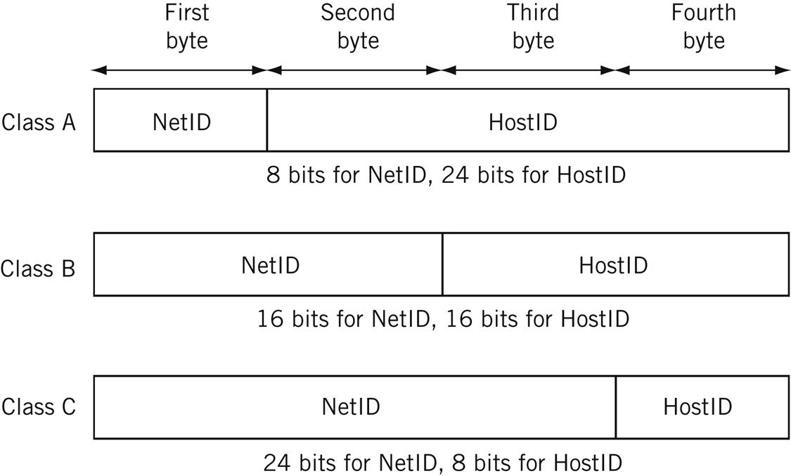
The basic concepts of classful IPv4 addressing are shown in Figure 5.3 for the three most common classes—A, B, and C. The figure shows the Internet name assigned to the IPv4 address, the default network mask and prefix length for each of the three common classes, and the IPv4 address in dotted decimal.
Note that when no network mask is given, the class of the address is determined by the value of the initial bits of the address, as already described. The network mask can move this boundary, but in practice only to the right in classful addressing.
Classless IPv4 addressing, on the other hand, as used on routers, does not derive a default subnet mask or prefix length. The prefix length for classless IPv4 addressing must be given (by the netmask) to properly place the boundary between NetID and HostID portions of the IPv4 address.
IP addresses, both IPv4 and IPv6, can be public or private. Public network address spaces are assigned by a central authority and should be unique. Private network addresses are very useful, but are not guaranteed to be unique. Therefore, the use of private network address spaces has to be carefully managed, because routers on the Internet would not work properly if a LAN showed up in two places at the same time. Nevertheless, the use of private address spaces in IP is popular for perceived security reasons. The security aspects are often overemphasized: The expansion of the locally available address space is the key reason for private address use. (If you have one IP address and three hosts, you have a problem without private addressing.) But private address spaces must be translated to public addresses whenever a packet makes it way onto the global public Internet.
Moreover, private IP addresses are not routable outside a local network, so a router is not allowed to advertise a route to a private address space onto the public Internet. Note that private addresses are just as routable as public ones within your own network (as on the Illustrated Network), or by mutual consent with another party. They are not generally routable on the global public Internet due to their lack of uniqueness and usual practices.
Almost all networks today rely on private network addresses to prevent public IPv4 address exhaustion, so these addresses are not just to test networks and labs any longer. Customer-edge routers often translate between a large pool of private (internal) and a smaller pool of public (external) addresses and insulate the local LAN from the outside world. We’ll talk more about private IPv4 address in the next section of this chapter.
When obtaining a public IP address, a user or organization receives an address space that should be globally unique on the Internet. (Sadly, you often find yourself “blackholed” to nowhere for some ISP to route your packets because someone else used your address space internally for some private network without permission!) This first piece is the network portion (prefix) of an IP address space, such as 191.255.0.0. This example uses a so-called “Martian” IPv4 address, which is a valid IP address, but not used on the Internet. Technically, the address space beginning with 191.255 is reserved, but could be assigned in the future. The 0.0 ending means an IP network is referenced, and not a host (in this case, but hosts sometimes have IPv4 addresses that end with 0). Some TCP/IP protocol stacks struggle with IPv4 addresses ending in 0 or 255, so it is best to avoid them. The host portion of the IPv4 address is assigned locally, usually by the LAN network administrator. For example, a host could be assigned IPv4 address 191.255.14.44.
The examples in this chapter use the manual, static IP address assignment method. When this method is used with public IP addresses, the organization still either obtains the IP network address range on its own, or uses the range of IP addresses assigned to the organization by its ISP. The Dynamic Host Configuration Protocol (DHCP) makes it possible to assign IP addresses to devices in a dynamic fashion. DHCP is the method many organizations use either for security reasons (to make it harder to find device IP addresses) or to assign a unique IP address to a device only when it actually needs to access the Internet. There are many more uses for dynamic IP address allocations on the Internet, and much more to discuss, and DHCP will be explored in a later chapter.
When the topic is routers, IP addresses are often written in the <netid, hostid/prefix> form to determine the netid/hostid boundary. To completely identify a particular host on a particular network, the whole address is needed. When all 32 bits of the IPv4 address are given, and the prefix is not, this is called a host address on a router. In classless routing, there is no fixed separation point between the network and host portion of the IP address: It is completely determined by the prefix, which must be known. In dotted decimal notation, the full range of possible IP addresses can run from 0.0.0.0 to 255.255.255.255. Prefixes can run from /0 (a special, but useful, case) to /31. Until recently, the /31 prefix was often useless to routers (some organizations still avoid them, while others embrace them), as we will see in a later chapter, and the /32 prefix is the same as the host address.
Private IPv4 Addresses
RFC 1918 established private address spaces for Classes A, B, and C to be used on private IP networks, and these are still respected in classless IP addressing. Books such as this one, where it is not desirable to use public IP addresses for examples, use RFC 1918 addresses throughout, much like using “555” telephone numbers in movies and on TV.
There are also IP address ranges set aside specifically for documentation, established in RFC 5737. These are 192.0.2.0/24 (TEST-NET), 198.51.100.0/24 (TEST-NET-2), and 203.0.113.0/24 (TEST-NET-3). There are even a few other “documentation” ranges for specialized applications. However, this book uses RFC 1918 addresses (except for the chapter on NAT) because they are so common, a book like this is not technically “documentation,” and because the subnets are all the same size (/24) and often similar (192 and 198, for example).
The private IP address ranges follow:
• Class A: 10.0.0.0 through 10.255.255.255 (10.0.0.0/8, or just 10/8)
• Class B: 172.16.0.0 through 172.31.255.255 (172.16.0.0/12, or just 172.16/12)
• Class C: 192.168.0.0 through 192.168.255.255 (192.168.0.0/16, or just 192.168/16)
There are three very important points that should always be kept in mind regarding private addresses. First, these addresses should never be announced by a routing protocol on a local router to the public Internet. However, these addresses are frequently assigned and used when they are isolated or translated to other addresses. We’ll look at network address translation (NAT) in a later chapter. In summary,
• Private IP addresses are not routable outside the local network (they cannot be advertised to the public Internet).
• They are widely used on almost all networks today (even our small home network with DSL uses private IP addresses).
• Private addresses are usually translated with NAT at an edge router to map the private addresses used on a LAN to the public address space used by the ISP.
Understanding IPv4 Addresses
IP addresses and their prefixes are read in a certain way and have special meanings depending on how they are written and used. For example, the classful IPv4 address 192.168.19.48 is read as “host 48 on IP network 192.168.19.0.” In a classless environment, as on a router, the prefix length, in this case /24, must be known. Routers often drop trailing zeros, 192.168.19.0/24 is the same as 192.168.19/24. All IP network addresses must have the bits in the host address field set to 0 and this address cannot be assigned to any host. (Typically, nothing on a host prevents this address assignment. It just probably won’t work properly.) Note that while the table is describing a particular /24 address in the examples, it’s not the address itself but its location in the field specified by the mask that is critical.
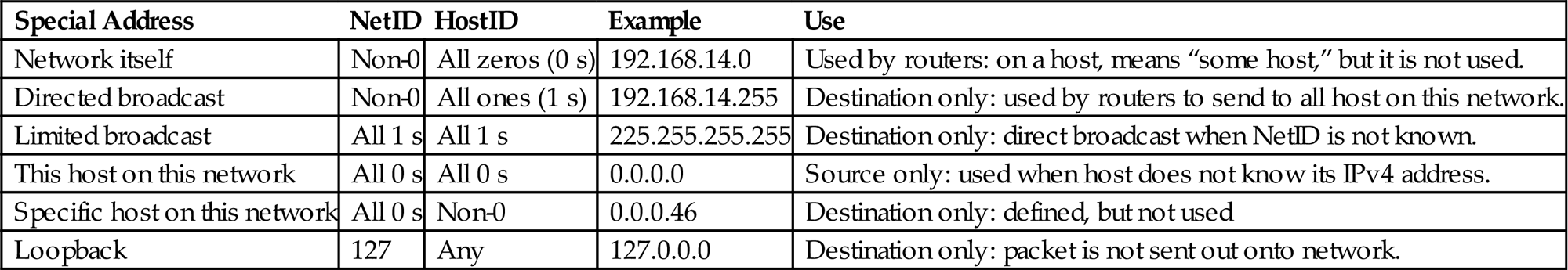
Table 5.1 lists some specific forms of IPv4 addresses, what they look like, and whether they can be used as a source or destination address or have some other special use.
Table 5.1
Special Forms of IPv4 Addresses, Showing How Some Are Limited in Application to Source or Destination
| Special Address | NetID | HostID | Example | Use |
| Network itself | Non-0 | All zeros (0 s) | 192.168.14.0 | Used by routers: on a host, means “some host,” but it is not used. |
| Directed broadcast | Non-0 | All ones (1 s) | 192.168.14.255 | Destination only: used by routers to send to all host on this network. |
| Limited broadcast | All 1 s | All 1 s | 225.255.255.255 | Destination only: direct broadcast when NetID is not known. |
| This host on this network | All 0 s | All 0 s | 0.0.0.0 | Source only: used when host does not know its IPv4 address. |
| Specific host on this network | All 0 s | Non-0 | 0.0.0.46 | Destination only: defined, but not used |
| Loopback | 127 | Any | 127.0.0.0 | Destination only: packet is not sent out onto network. |
IPv4 addresses in example formats such as 0.0.0.46 and 192.168.14.0 are never actually seen as packet header addresses. Loopback addresses are used on hosts and routers for testing and aren’t even numbered on the interface. All systems “know” that packets sent to the loopback addresses (any IPv4 address starting with 127) are not sent out the network interface. Note that on a router, the “loopback interface,” as opposed to the loopback address, is often used to hold the IP address of the router itself (and not a particular interface). Because routers have many interfaces, using the “router address” as a source of destination address helps make the router reachable—and manageable—even when a particular interface is down.
When these forms are not used in their defined roles (e.g., when something like 172.16.255.255 is used as a packet source address instead of a destination), the result is usually an error.
The IPv6 Address
In addition to IPv4 (often written as just IP), there is IP version 6 (IPv6). IPv6 was developed as IPng (“IP: The Next Generation” because the developers were supposedly fans of the TV show “Star Trek: The Next Generation”). (IPv5 existed and is defined in RFC 1819 as the Streams 2 [ST2] protocol.)
This section is not intended to be an exhaustive investigation of IPv6. The emphasis here is on the IPv6 header and address, and how IPv6 will affect router operation. IPv6 has been around since about 1995, but pressure to transition from IPv4 to IPv6 is mostly recent. (The exhaustion of the IPv4 address space has been delayed mainly through the use of NAT and DHCP.) Today, the pressure for transition from IPv4 to IPv6 comes mainly from network service providers and operators and other groups with large internal networks, such as cellular telephone network operators, as well as places with large populations with mobile devices of all kinds, including cars, tablets, and anything that can attach to the “Internet of Things” (IoT).
In some applications, major IPv6 addresses are confined to the core of large IP networks, and customers and users still see only IPv4 addresses.
Features of IPv6 Addressing
The major features of IPv6, such as IPSec, have nearly all been back-ported into IPv4. However, the major design features of IPv6 follow:
• An increase in the size of the IP address from 4 bytes (32 bits) to 16 bytes (128 bits).
• An increase in the size of the IP header from 24 bytes (192 bits) to 40 bytes (320 bits). (Although aside from the address fields, the header is actually smaller than in IPv4.)
• Enhanced security capabilities using IPSec (if needed).
• Provision of special “mobile” and autoconfiguration features.
• Provision for support of flows between routers and hosts for interactive multimedia.
The IPv6 address increases the size of the IP address from 4 bytes (32 bits) to 16 bytes (128 bits). For backward compatibility, all currently assigned public IP addresses are supported as a subset of the IPv6 address space. The IPv6 address size increases the overall IP packet header size (and total TCP/IP overhead) from the current 24 bytes (192 bits) to 40 bytes (320 bits). However, the IPv6 header is much simpler than the IPv4 header.
IPv6 includes autoconfigured address and special support for mobile (not always wireless) users. A new mobile feature called chained headers might allow the faster forwarding of IPv6 packets through routers, and forbids intermediate fragmentation of IPv6 packets in routers. The path MTU size must always be respected in IPv6 routers.
IPv6 features support for what are called “flows.” Flows were included in IPv6 because forwarding packets at wirespeed was originally considered impossible. Flow caching (the association of IPv6 packets into flows with similar TCP/IP header fields) was thought to be the workaround. However, flow caching is now widely discredited in the IPv4 world and flows are now established and applied to stateful firewall filters (Chapter 28). The flow field in IPv6 is normally set to all 0 s.
IPv6 is a good fit for a dynamic environment. There are many address discovery options bundled with IPv6, including support for autoconfiguration, finding the maximum path MTU size (to avoid the need for fragmentation, which IPv6 routers will not do), finding other hosts’ MAC addresses without ARP broadcasts, and finding routers other than the default.
The last major feature in IPv6 is a standard for header compression and extension. At first, these two features may seem contradictory, but they are actually complementary. Header compression addresses situations where the 40 bytes of the IPv6 header consists mostly of “empty” or repeated fields (like all-0 bit fields). In IPv6, there is a standard way of compressing the 40 bytes of the header down to 20 or so. There is also a way to extend these IPv6 header fields for future new features (IPv4 also has header extension options).
IPv6 Address Types and Notation
There are no broadcast addresses at all in IPv6, even directed broadcasts (these were favorites of IPv4 hackers). In IPv6, multicast addresses serve the same purpose as broadcasts do in IPv4. The difference between IPv6 anycast and multicast is that packets sent to an anycast IPv6 address are delivered to one of several interfaces, while packets sent to a multicast IPv6 address are delivered to all of many interfaces.
There is no such thing as dotted decimal notation for IPv6. All IPv6 addresses are expressed in hexadecimal. They could be expressed in binary as well, but 128 0 s and 1 s are tedious to write down. IPv6 addresses are written in 8 groups of 16 bits each, or 8 groups of 4 hexadecimal numbers, separated by colons. Some examples of IPv6 addresses follow (you may see the hex “letters” in upper-case or lower-case):
FEDC:BA98:7654:3210:FEDC:BA98:7654:3210
1080:0000:0000:0000:0008:0800:200 C:417 A
Because this is still a lot to write or type, there are several ways to abbreviate IPv6 addresses. For example, any group can leave out leading 0 s, and all-0 groups can be expressed as just a single 0. A long string of leading 0 s can simply be replaced by a double colon (::). In fact, as long as there is no ambiguity, groups of 0 s anywhere in the IPv6 address can be expressed as ::. The double colon can only be used once in an IPv6 address.
Even with these conventions, the first IPv6 address given earlier cannot be compressed at all. The second address can be expressed as
1080::8:800:200 C:417 A
This is better than writing out all 128 bits, even as hexadecimal. Because only one set of double colons can ever be used inside an IPv6 address,
1080:0000:0000:9865:0000:0000:0000:4321
could be written as
1080:0:0:9865::4321
or
1080::9865:0:0:0:4321
but never as
1080::9865::4321
(How big are the missing groups of 0 s to the left or right of 9865?)
A special case in IPv6 is made for using IPv4 addresses as IPv6 addresses. For example, the IPv4 address 10.0.0.1 could be written in IPv6 as
0:0:0:0:0:0:A00:1
or even
::A00:1
IPv4 addresses in IPv6 can still be written in dotted decimal as
::10.0.0.1
The double colon at the start is the sign that this is an IPv6 address even though it looks just like an IPv4 address. Many routers and other devices allow this convention.
IPv6 Address Prefixes
The first few bits of an IPv6 address do reveal something about the IPv6 address, although IPv6 addressing is in no way classful. IPv6 addresses have an address type, and the type is determined by the format prefix of the IPv6 address. There are reserved addresses in IPv6 as well, for things like loopback (::1), multicast (starting with FF), and so on. There is also an unspecified address consisting of all 0 s (0:0:0:0:0:0:0:0, compressed as just ::) that can be used as a source address by an IPv6 device that has not yet been assigned an IPv6 address. IPv6 address space is also reserved for OSI-RM Network Service Attachment Point (NSAP) addresses, and some other protocols.
All of these format prefixes are supposed to be given in hexadecimal, not binary. An IPv6 address that begins with 1101 means 0001 0001 0000 0001, and is the same as 11::1.… An IPv6 multicast address begins with FF and means 1111 1111:1111 1111.
There are several basic forms of IPv6 address. Like many IPv4 addresses, IPv6 address spaces are often handed out by ISPs to their customers, usually starting with 200x. There are also ways to assign variable-length fields for the registry identifier (the authority that assigned this IPv6 address space to the ISP), provider identifier (the ISP), subscriber identifier (the customer), subnet identifier (a group of physical links), and the interface identifier (such as the MAC address). However, most ISPs will assign IPv6 addresses just as they do IPv4 addresses (i.e., as a network address space and prefix length). Provider independent IPv6 addresses are not handed out by ISPs.
There used to be two types of local IPv6 addresses: site-local and link-local. Local IPv6 addresses are addresses without global significance, and they can be used over and over again as long as they do not cause confusion to hosts or routers. Local addresses start with the same 7 bits: 1111 111 or FE in hexadecimal (overall, the first 10 bits are important). Site-local addresses are now deprecated (the Internet word for “more than obsolete”). Link-local addresses can be used between two devices that are part of the same broadcast domain or on a point-to-point link.
Private IPv6 addresses usually begin with FC00 (the full form is FC00::/7) and are called unique local-unicast addresses (ULA or ULA local or even ULA-L). Usually, link-local IPv6 addresses end with a 64-bit representation (called EUI-64 by the IEEE) of the 48-bit MAC address. The EUI-64 is a concatenation of the 24-bit OUI used in the MAC address with the 40-bit extension formed by prepending the 16 bits 0xFFFE to the lower 24 bits of the MAC address.
Subnetting and Supernetting
Let’s take a look at all aspects of finding and moving the boundary between network and host bits in the IP address. The moveable boundary is an important one, because routers performing indirect delivery generally only need to look at the NetID or prefix of the entire IP address to determine the next hop and then find the output interface to send the packet on its way. Of course, direct delivery requires both prefix and host addressing examination, which is why the location of the NetID/HostID boundary is so important.
How do routers and hosts know precisely where the boundary between prefix and host address is in the IP address? Only when this prefix/host boundary is known will the device know if the next hop is a router. And that, as we’ll see in a later chapter, makes all the difference.
In the following discussions, the examples used are chosen for their simplicity, not for completeness.
Subnetting in IPv4
The IP address space was originally classful. (Of course, they didn’t know it was classful back then—it was just the IP address space). As such, it contained a number of special purpose and private addresses. These characteristics of the first three classes, which have already been discussed, are summarized in Table 5.2.
Table 5.2
Classful IPv4 Addresses and Default Masks
| Class | Initial Bits | Range | Default Mask |
| A | 0 | 0 to 127 | 255.0.0.0 |
| B | 10 | 128 to 191 | 225.255.0.0 |
| C | 110 | 192 to 223 | 255.255.255.0 |
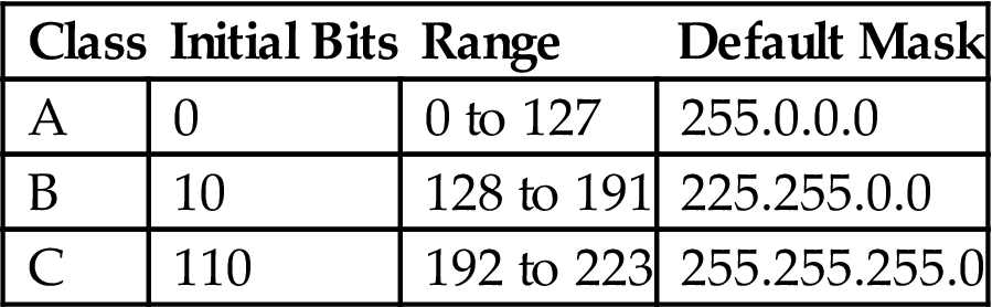
Note: The value of the initial bits automatically limits the range of addresses possible in each class.
Even before the Web exploded and everyone needed an IP network address for their PCs and Web sites, it was obvious that Class A and B addresses would quickly become exhausted, leaving only Class C addresses for most networks. However, these addresses only allow 254 hosts per IP network (0 and 255 were for the network and broadcast addresses). Many networks quickly exceeded this limit.
Also, Internet core routers must have a separate routing table entry for every reachable IP network. For example, in 1993 there were fewer than 10,000 routes on most backbone routers, and this did not grow to 100,000 until about 2001. Now, it is not uncommon to add 2000 routes per week.
Subnetting Basics
IP address subnetting applies to any IP address. The original application of subnetting was so that point-to-point links between routers did not require a full /24 address for each link. Subnetting also allowed a single Class C IP address to be used on small LANs having fewer than 254 hosts connected by routers instead of bridges. Bridges would simply shuttle frames among all of the ports on the bridge, but routers, as packet layer devices, determine the output interface for a packet based on the network portion of the IP address. If only one address is assigned to the entire site, but two LANs on the site are connected through a router, then the address must be subnetted so that the router functions properly. Basically, you need to create two distinct address spaces, and the IP host addresses assigned on each LAN segment must be correct as well. The LAN segments now become subnets of the main IP address space.
Subnetting is done using an IP address mask. The mask is a string of bits as long as the IP address (32 bits in the case of IPv4). If the mask bit is a 1 bit, the corresponding bit in the IP address is part of the network portion of the IP address. If the address bit is part of the host portion, the corresponding mask bit is set to a 0 bit. A mask of 255.255.0.0 means that the first 16 bits of the IP address are part of the network address and the last 16 bits are part of the host portion of the address.
All subnet masks must end in 0, 128, 192, 224, 240, 248, 252, 254, or 255—the values of each bit position as they are “turned on” left to right in any octet. Strangely, subnet masks were once allowed to turn on bits that were “noncontiguous” (not starting at the left of the address without gaps). This is no longer true, and the effect is to restrict masks to the ending values listed. Note that 255.224.0.0 is a valid subnet mask, as is 255.255.248.0 and 255.255.255.252. Once the 1 bits stop, the rest of the subnet mask must be set to all 0 bits.
Subnet masks can be written in as many forms as there are for IP addresses: dotted decimal notation, bit string, octal, or hexadecimal. Seeing subnet masks in either dotted decimal or hexadecimal notation, or the newer prefix “slash” notation, also known as CIDR notation, are the most common. Sometimes the default mask for an IP address class is called the “natural mask” for that type of address. In all cases it is possible to change the default mask to move the boundary between the network and host portions of the IP address to wherever the device needs to see it. All devices, whether hosts or routers, which need to route the packets within the subnetted network, must have identical masks. All routing protocols in wide use today exchange subnet mask information together with routing information.
The use of the default masks for the original classful IP address space is shown in Table 5.3. The more bits, the more network identifiers, and the fewer bits, the fewer host identifiers possible.
Table 5.3
Use of Default or “Natural” Subnet Masksa
| Original Class | Default Mask | Network/Host Bits | Example Interpretation |
| A | 255.0.0.0 | 8/24 (/8 prefix) | 10.24.215.86 is host 0.24.215.86 on network 10.0.0.0 |
| B | 255.255.0.0 | 16/16 (/16 prefix) | 172.17.44.200 is host 0.0.44.200 on network 172.17.0.0 |
| C | 255.255.255.0 | 24/8 (/24 prefix) | 192.168.27.3 is host 0.0.0.3 on network 192.168.27.0 |
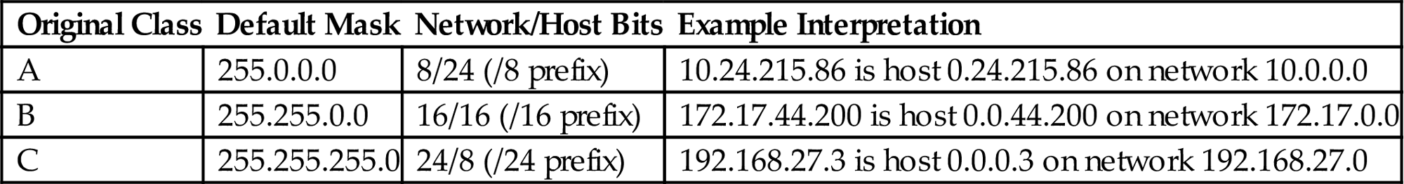
aThe more bits, the more network identifiers; the fewer bits, the fewer host identifiers possible.
Subnetting moves the boundary between the network and host for a particular classful IP address to the right of the position where the boundary is normally found. We will see later that supernetting moves the boundary between network and host for a particular classful IP address to the left of this position. CIDR (which uses VLSM) can move the boundary anywhere.
It is important to realize that subnetting does not change anything with respect to the outside world. Internet routers still deliver the packets as before. It is the customer or site router that applies the subnet mask and delivers packets to the subnets. Instead of the usual two parts of the IP address, network, and host, we now have network, subnet, and host. However, even at the beginning of the classful era, Class A blocks were subnetted into /16 s and /24 s internally as appropriate.
Look at a simple LAN (192.168.15.0) before and after subnetting, as shown in Figure 5.4. The subnet creates two equal-sized subnets, but the Internet routers deliver packets as before. The subnet adds one “extra” bit to the default Class C mask. If this bit is 0, the first subnet is intended, and if the bit is 1, then the second subnet is intended. The hosts must be numbered according to the subnet, naturally, and all have the same subnet mask so they can determine which addresses are still on their subnet (same NetID) and which are not (different NetID).
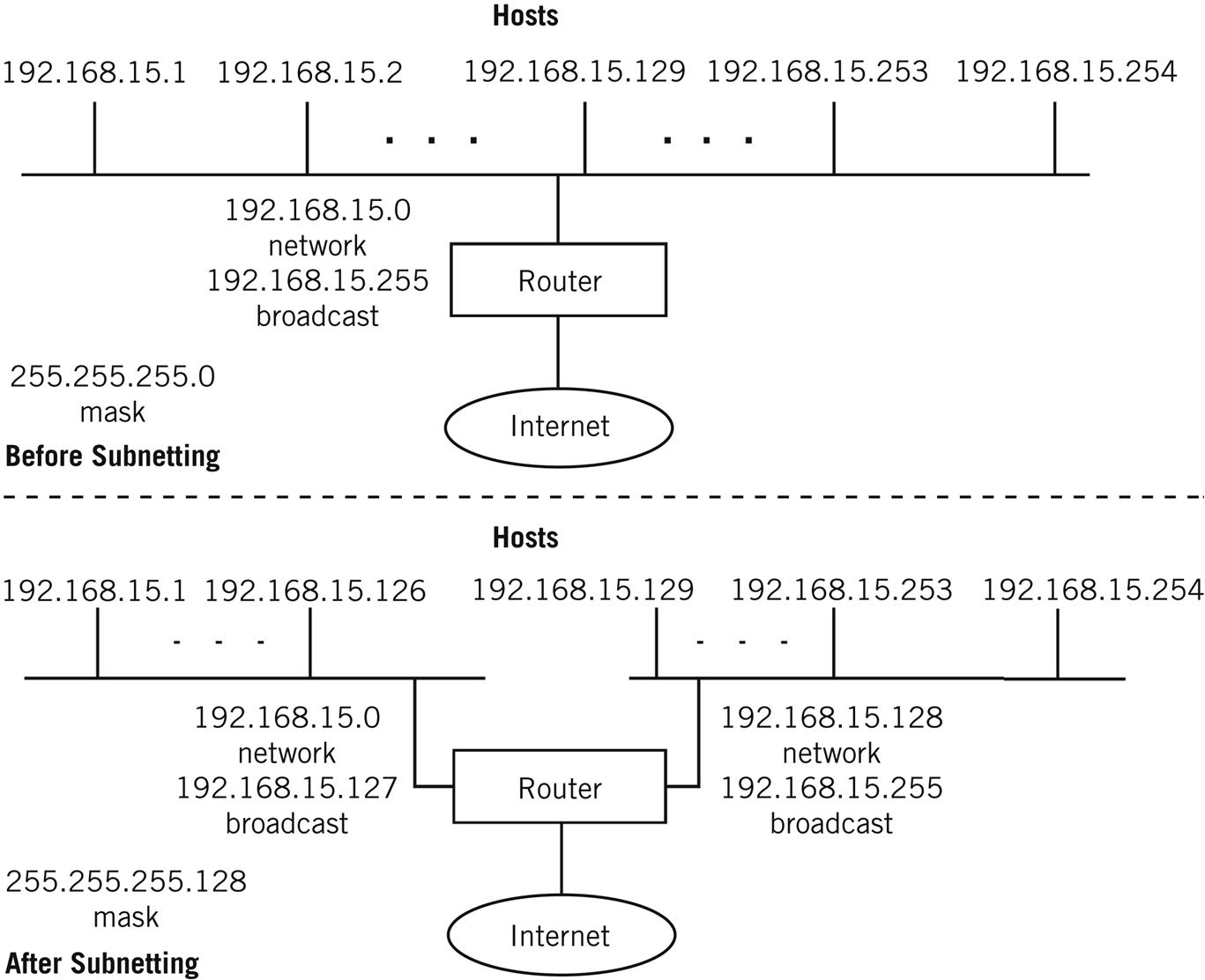
Many implementations will not allow the assignment of the first subnet address (the network) or the last (broadcast). A LAN with 254 hosts subnetted into two subnets only yields 126 host addresses per subnet, not 127.
A sometimes tricky subnet issue is determining exactly what the subnet address (all 0 bits after the mask) and broadcast address (all 1 bits after the mask) are for a given IP address and subnet mask. This can be difficult because subnet masks do not always fall on byte boundaries as do classful addresses. An IP address like 172.31.0.128 might not look like the address of the network itself, but it might be. A network address, in some implementations of TCP/IP, cannot be assigned to a host. (172.31.0.128 with a subnet mask of 255.255.255.128 is a network address.) Consider the address 172.18.0.126 with a subnet mask of 255.255.255.192. What is the subnet and broadcast address for this subnet? What range of host addresses can be assigned to this subnet? These questions come up all the time, and there are utilities available on the Internet that do this quickly. But here’s one way to do it by hand.
The first thing to do is to mask out the network portion of the IP address with the subnet mask by writing down the mask bits. Then the subnet portion of the address can be easily marked off by “turning on” the masked bits. Next, it is easy to form the subnet and broadcast address for the subnet by setting the rest of the bits in the address (the host bits) first to all 0 bits (network) and then to all 1 bits (broadcast). The resulting address range forms the limits of the subnet.
Let’s look at an example. Figure 5.5 shows how to derive the network and broadcast address answers for IP address 172.18.0.126 with the subnet mask 255.255.255.192.

These answers are important when subnetting the IP address space because care is needed to assign host addresses to the proper subnets (and router interfaces). Having a “discontiguous” classful major network that has been subnetted so that part of the space is reached through one interface of the router (“10.24.0.0 over here…”), and the other part of the subnetted major network is reached through another interface (“10.25.0.0 over there …”) can be a problem unless care is taken with the subnets and the masks that establish them.
One of the issues using RFC 5737 addresses for books such as these is that all three networks are “/24 s,” which means that any subnetting cannot fall on a byte boundary. That’s one reason the 10.0.0.0/8 RFC 1918 private address remains so popular: it is easily subnetted on byte boundaries (/16, /24) and therefore the most flexible private address.
CIDR and VLSM
Today, the standard methods for moving the network/host address boundary are variable-length subnet masking (VLSM) for host addressing and routing inside a routing domain, and classless interdomain routing (CIDR) for routing between routing domains. (We’ll talk more about routing domains later in this book. For now, think of a routing domain as an ISP’s collection of routers.) And although treated separately here for introductory reasons, it is important to realize that VLSM is the fundamental mechanism of CIDR.
CIDR (defined in RFC 1519) and VLSM (defined in RFC 1860) address more general issues than simple subnetting. We’ve been looking at addresses from the host perspective in this chapter so far. Let’s discuss CIDR from the router perspective.
CIDR was an immediate answer to two problems: first, the impending exhaustion of the Class A and Class B address space, and second, the rapid increase in Internet core routing table sizes to handle the many Class C addresses required to handle new users.
In CIDR, a block of contiguous IP addresses from the former classful address space are assigned in a group, such as groups of Class C addresses. This allows a service provider or large customer to configure IP networks from a few hosts up to 16,384 hosts. The number of contiguous addresses needed is determined by a simple count of the number of host addresses required. The original CIDR plan, applied to Class C addresses, is shown in Table 5.4. Contiguous address numbers flow seamlessly between former class boundaries, allowing assignment of address “chunks” for larger networks.
Table 5.4
Address Grouping Under CIDRa
| Number of Hosts Needing Addresses | Class C Addresses Given by Registry |
| Fewer than 256 | 1 Class C network |
| Fewer than 512 but more than 256 | 2 contiguous Class C networks |
| Fewer than 1024 but more than 512 | 4 contiguous Class C networks |
| Fewer than 2048 but more than 1024 | 8 contiguous Class C networks |
| Fewer than 4096 but more than 2048 | 16 contiguous Class C networks |
| Fewer than 8192 but more than 4096 | 32 contiguous Class C networks |
| Fewer than 16,384 but more than 8192 | 64 contiguous Class C networks |
aContiguous address numbers flow seamlessly between former class boundaries, allowing assignment of address “chunks” for larger networks.
The CIDR RFC does not “subtract” two host addresses for the network itself (final bits all 0 s) and a broadcast address (final bits all 1 s). CIDR applies mainly to router operation, and routers do not assume any structure of the IP addresses in the packets they route. The limitation on assigning the high and low IP addresses to a host interface is a function of the host TCP/IP implementation (and some, like routers, do not enforce any limitations at all).
CIDR changed the terminology that applied to IP addresses. Routes to IP networks are now represented by prefixes. A prefix consists of an IP network address, followed by a slash (/), and followed with an indication of how many of the leftmost contiguous bits in the address are part of the network mask applied for routing purposes. For example, before CIDR, the Class C address 192.168.64.0 would ordinarily have a mask of 255.255.255.0. Subnetting could add bits to this major network mask, but only in the fixed patterns and values outlined in the previous section. CIDR enabled a “CIDR-ized” network address to be represented as 192.168.64.0/18, and that was all the information needed. Sometimes this is abbreviated even further to just 192.168.64/18, but the two forms are equivalent. The notation just means that a “subnet mask 18 bits long should be applied to 192.168.64.0.” This is the same as writing “192.168.64.0 with mask 255.255.192.0” but in more compact form.
Table 5.5 shows all possible prefix lengths, their netmasks in dotted decimal, and the number of classful networks the prefix represents. It also shows the number of usable IPv4 addresses that can be assigned to hosts once the network address itself and the directed broadcast address are subtracted. We’ll talk about the special 0/0 address and prefix length in Chapter 8. All possible mask lengths are shown for /1 to /32. The /0 mask, when applied to the 0.0.0.0 IP address, matches the whole Internet and is discussed in the routing chapters.
Table 5.5
CIDR Prefixes and Addressinga
| Prefix Length | Dotted Decimal Netmask | Number of Classful Networks | Number of Usable IPv4 Addresses |
| /1 | 128.0.0.0 | 128 Class A’s | 2,147,483,646 |
| /2 | 192.0.0.0 | 64 Class A’s | 1,073,741,822 |
| /3 | 224.0.0.0 | 32 Class As | 536,870,910 |
| /4 | 240.0.0.0 | 16 Class A’s | 268,435,454 |
| /5 | 248.0.0.0 | 8 Class A’s | 134,217,726 |
| /6 | 252.0.0.0 | 4 Class A’s | 67,108,862 |
| /7 | 254.0.0.0 | 2 Class A’s | 33,554,430 |
| /8 | 255.0.0.0 | 1 Class A or 256 Class B’s | 16,777,214 |
| /9 | 255.128.0.0 | 128 Class B’s | 8,388,606 |
| /10 | 255.192.0.0 | 64 Class B’s | 4,194,302 |
| /11 | 255.224.0.0 | 32 Class B’s | 2,097,150 |
| /12 | 255.240.0.0 | 16 Class B’s | 1,048,574 |
| /13 | 255.248.0.0 | 8 Class B’s | 524,286 |
| /14 | 255.252.0.0 | 4 Class B’s | 262,142 |
| /15 | 255.254.0.0 | 2 Class B’s | 131,070 |
| /16 | 255.255.0.0 | 1 Class B or 256 Class C’s | 65,534 |
| /17 | 255.255.128.0 | 128 Class C’s | 32,766 |
| /18 | 255.255.192.0 | 64 Class C’s | 16,382 |
| /19 | 255.255.224.0 | 32 Class C’s | 8,190 |
| /20 | 255.255.240 | 16 Class C’s | 4,094 |
| /21 | 255.255.248.0 | 8 Class C’s | 2,046 |
| /22 | 255.255.252.0 | 4 Class C’s | 1,022 |
| /23 | 255.255.254.0 | 2 Class C’s | 510 |
| /24 | 255.255.255.0 | 1 Class C | 254 |
| /25 | 255.255.255.128 | 1/2 Class C | 126 |
| /26 | 255.255.255.192 | 1/4 Class C | 62 |
| /27 | 255.255.255.224 | 1/8 Class C | 30 |
| /28 | 255.255.255.240 | 1/16 Class C | 14 |
| /29 | 255.255.255.248 | 1/32 Class C | 6 |
| /30 | 255.255.255.252 | 1/64 Class C | 2 |
| /31 | 255.255.255.254 | 1/128 Class C | 0 |
| /32 | 255.255.255.255 | 1/256 Class C (1 host) | − (1 host route) |

aAll possible mask lengths are shown, for /1 to /32. The /0 mask matches the whole Internet and will be discussed in the routing chapters.
Even when CIDR was used, all bits after the IP network address had to be zero, an aspect of IP addressing that did not change. For example, 192.168.64.0/18 was a valid IP network address, but 192.168.64.0/17 was not (due to the presence of the “1” bit for the “64” in the 17th bit position). This aspect of CIDR is shown in Figure 5.6. The IP network 192.168.64.0/18 is a CIDR “supernet” because the mask contained fewer bits than the natural mask in classful IP addressing.

CIDR allowed the creation of a network such as 192.168.64.0/18 with 16,384 hosts (14 bits remain for the host portion of the 192.168.64.0 network) instead of requiring 64 separate IP network addresses to be assigned and configured. CIDR did more than allow the grouping of contiguous Class C addresses into bigger networks than possible before. Once the principle was established, CIDR allowed the aggregation of all possible IP addresses under the specified prefix into this one compact notation. This kept routing table sizes under control in the late 1990s.
Where does VLSM fit in? As mentioned, VLSM applied more to hosts and a single routing domain. Basically, in the days of classful IP addressing, all subnets of the same address had to have the same mask length. So you could, for example, subnet 10.0.0.0/8 into 10.0.0.0/16 subnets, but every device on every subnet had to have the same /16 mask. This could be okay if all the subnetted LANs had roughly the same number of hosts, but what about point-to-point links between routers on the subnet? They could get by with a /31 or /30 mask because there were only two endpoints, but they had to have room for the same thousands of hosts as the rest of the /16.
Note that the Illustrated Network is an offender: The links between our routers use /24 masks for point-to-point links (falling on an easy-to-use byte boundary). We would not do this in the real world, but it will help our understanding of simple examples when we turn to routing later in this book.
IPv6 Addressing Details
Let’s take a quick look at some of the differences between IPv4 and IPv6 addressing. The use of the IPv6 address space is determined by the value of the first few bits of an IPv6 address. Routing in IPv6 is similar to IPv4 with CIDR and VLSM, but there are a few points to be made to clarify this.
IPv6 addresses can be provider based, provider independent, or for local use. All provider-based IPv6 addresses for “aggregatable” global unicast packets begin with either 0010 (2) or 0011 (3) in the first four bit positions of the 128-bit IPv6 address.
Typical IPv6 address prefixes would look like:
2001:0400::/23
2001:05FF::/29
2001:0408::/35
and so on.
The 64 bits that make up the low-order bits of the IPv6 address must be in a format known as the EUI-64 (64-bit Extended Unique Identifier). Normally, the 48-bit MAC address consists of 3 bytes (24 bits) assigned to the manufacturer and 3 bytes (24 bits) for the serial number of the NIC itself. A typical MAC address would look like 0000:900 F:C27E. The next to the last bit in the first byte of this address is the global/local bit, and is usually set to a 0 bit (global). This means that the MAC address is globally assigned and is using the native address assigned by the manufacturer. In EUI-64 format, this bit is flipped and usually ends up being set to a 1 bit (the meaning is flipped too, so in IPv6, 1 here means global). This would make the first byte 02 instead of 00. For example, 0000:900 F:C27E becomes 0200:900 F:C27E (not always, but this is just a simple example).
To convert a MAC address to a 64-bit address that can be used on an interface for the host portion of an IPv6 address, we insert the string FFFE between the manufacturer and the serial number fields of the MAC address (between the first and the last 3 bytes). The MAC address becomes 0200:90 FF:FE0F:C27E. This is more easily shown as follows:
Link-local IPv6 addresses begin with 1111 1110 1000 (FE80 in hexadecimal, making the first two bytes FE80 if all of the trailing 6 bits in the second byte are 0 bits). ULA local addresses are in the form FC00::/7. In IPv6, interfaces are expected to have multiple addresses, a shift from IPv4. It’s common to find three IPv6 addresses on an interface: global, link local, and site local. It is also common to use multiple link-local addresses, one based on the MAC and the other based on random numbers.
Both forms usually end with the 48-bit IEEE MAC address, but again with the added FFFE bits to form the EUI-64 identifier. The FC00 ULA address forms are used as the private addresses in IPv6 (just as 10.0.0.0 and the others in IPv4), and that’s how they are used in this book.
IPv6 addresses appear in sources and outputs about equally with capitals (FE80) or lower case (fe80), and we’ll see both. (In the RFCs, however, these are universally capitalized.) The major formats of the IPv6 address are shown in Figure 5.7.

Two routers connected by a small LAN can use the link-local IPv6 address of FE80::<EUI-64 formatted MAC address> on their interfaces. This type of address is never advertised by an IPv6 router attached to the Internet, and it cannot be used across subnets. On point-to-point links, a distinguishing identifier of the interface card other than the MAC address can be used at the end of the link-local address.
ULA-L addresses can include a 16-bit subnet field, so these forms of private IPv6 addresses can be used across subnets (through routers), but these addresses are not usually advertised onto the Internet. Using link-local and ULA-local IPv6 addresses, an organization can build an entire global network, but usually only if none of the traffic tries to travel across the Internet. If it does, IPv6 provider–based addresses are needed. This is similar to building a complete corporate network in IPv4 using the 10.0.0.0 private address space, but using Network Address Translation (NAT) for traffic that must travel across the Internet. However, in IPv6, hosts are assigned multiple addresses, some global and some local. In this case, the lower order bits (80 bits) of the site-local address (subnet and interface) are just pasted onto the higher fields (48 bits) of the provider-based forms of the IPv6 address.
What about private masks and routing in IPv6? As shown above, prefix masks in IPv6 have the same general form as prefix masks in IPv4. Here is a sample IPv6 link-local host address (this time in lower case hex notation) and one possible network prefix for it:
fe80::90:69ff:fea0:8000/128
fe80:: /64
As in keeping with all of the addresses used in this book, this IPv6 address is a private address. The /64 mask tells the router that the first 64 bits of the address are to be used for routing purposes.
IP Address Assignment
Most people get IP addresses from their ISP. But where do ISPs get their IP addresses? Large organizations can still apply for their own IP addresses independent from any ISP. To whom do they apply?
IP addresses (and the Internet domain names associated with them) were initially handed out by the Internet Assigned Number Authority (IANA). Today the Internet Corporation for Assigned Names and Numbers (ICANN), an international nonprofit organization, oversees the process of assigning IP addresses.
Actual IP addresses are handed out by the following Regional Internet Registries (RIRs):
• ARIN (American Registry for Internet Numbers) at www.arin.net—ARIN has handed out IP addresses for North and South America, the Caribbean, and Africa below the Sahara since 1997.
• RIPE NCC (Reseaux IP European Network Coordination Center) at www.ripe.net—RIPE assigns IP addresses in Europe and surrounding areas.
• APNIC (Asian Pacific Network Information Center) at www.apnic.net—APNIC assigns IP addresses in 62 countries and regions in Central Asia, Southeast Asia, Indochina, and Oceania.
• LACNIC (Latin American and Caribbean Network Information Center) at www.lacnic.net—LACNIC assigns IP addresses from ARIN in 38 countries, including Mexico.
• AfriNIC (African Network Information Center) at www.afrinic.net—AfriNIC took over assignment of African IP addresses from ARIN.
All of these Internet Registries databases (who has what IP address space?) combined are known as the Internet Routing Registry (IRR). Internet domain names comprise a related activity, but (like IP addresses) names must be globally unique and (unlike IP addresses) can be almost anything.
For the latest information on IP address assignment, which is always subject to change, see www.icann.org.
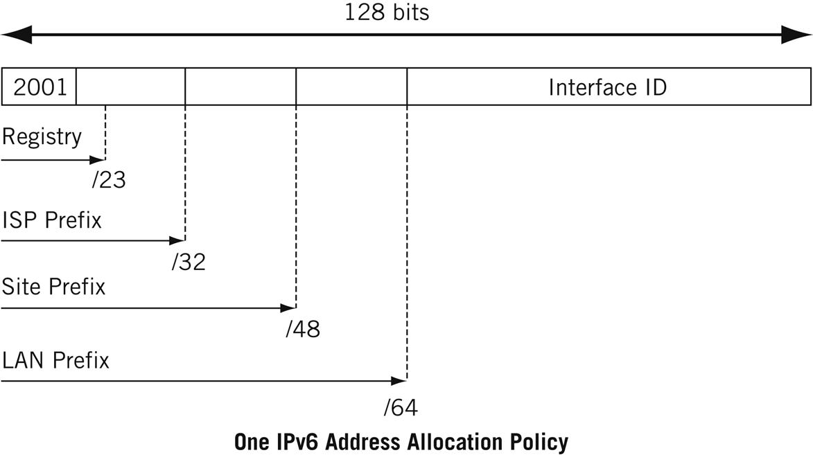
When it comes to IPv6, in particular, IANA still hands out addresses to the registries, which pass them along to IPv6 ISPs, who allocate IPv6 addresses to their customers. The current policy is given at www.arin.net/policy. An older policy is used in this chapter (see www.arin.net/policy/ipv6_policy.html) and uses these prefixes at each step of the process:
• 2001::/16 is reserved for IANA.
• IANA hands out a /23 prefix to each registry.
• Registry hands out a /32 or shorter prefix to an IPv6 ISP.
• ISP allocates a /48 prefix for each customer site.
• Local administrators add 16 bits for each LAN on their network, for a /64 prefix.
This scheme is shown in Figure 5.8. When the LAN is included, most IPv6 addresses have /64 network masks. This is the prefix length used on the Illustrated Network. IPv6 routers can perform the following tasks:
• Route traffic to a particular ISP based on the first 32 bits of the IPv6 destination address.
• Route traffic to a particular site based on the first 48 bits of the IPv6 destination address.
• Route traffic to a particular LAN based on the first 64 bits of the IPv6 destination address.
In practice, IPv6 core routers can look at (and build forwarding tables based on) /32 or shorter prefixes, routers inside a particular AS (routing domain) can look at /48 prefixes, and site routers on the customer edge can look at /64 prefixes to get traffic right to the destination LAN.
Now we can better understand the IPv6 address assigned to CE0 that we saw at the beginning of the chapter:
fc00:ffb3:d5:b:205:85ff:fe88:ccdb
or
FC00:FFB3:00D5:000B:0205:75FF:FE88:CCDB
Let’s break it down one element at a time and see where it all comes from:
• Registry—We use FC00 instead of 2001 to indicate a private ULA-local IPv6 address.
• ISP—We add Best ISP’s AS number of 65531 (0xFFB3) for LAN 1 or Ace ISP’s AS number 65527 (0xFE67) for LAN2.
• Site—We add telephony area code 213 (0x00D5) for the Los Angeles or 212 (0x00D4) for New York sites. (We could always use more of the phone number, but this is enough.)
• LAN—We add 11 (0x000B) for LAN1 or 12 (0x000 C) for LAN 2. These are borrowed from the IPv4 addresses.
• EUI-64—We add 0x0205 85FF FE88 CCDB for the hardware MAC address.
The mask is /64, naturally. Keep in mind that in the real world, none of this complex coding would be done.
Complete IPv4 and IPv6 Address Ranges
In this chapter, we’ve seen that some IPv4 and IPv6 addresses and ranges are reserved for special purposes. For IPv4 these include things like the private address ranges in RFC 1918 and documentation addresses in RFC 5737. This is good place to present two tables that list all the currently reserved IPv4 and IPv6 address ranges.
The reserved address ranges for IPv4 are shown in Table 5.6. The ranges for IPv6 are shown in Table 5.7. These address ranges should only be used for the purposes intended.
Table 5.6
Complete Reserved IPv4 Address Ranges
| Block | Range | # Addresses | Scope | Purpose |
| 0.0.0.0/8 | 0.0.0.0–0.255.255.255 | 16,777,216 | Software | Broadcast: RFC1700 p.4 |
| 10.0.0.0/8 | 10.0.0.0–10.255.255.255 | 16,777,216 | Private | Local use: RFC1918 |
| 100.64.0.0/10 | 100.64.0.0–100.127.255.255 | 4,194,304 | Private | CGNAT: RFC6598 |
| 127.0.0.0/8 | 127.0.0.0–127.255.255.255 | 16,777,216 | Host/loopback | Loopback: RFC990 |
| 169.254.0.0/16 | 169.254.0.0 – 169.254.255.255 | 65,536 | Subnet | DHCP use: RFC3927 |
| 172.16.0.0/12 | 172.16.0.0–172.31.255.255 | 1,048,576 | Private | Local use: RFC1918 |
| 192.0.0.0/24 | 192.0.0.0–192.0.0.255 | 256 | Private | Registry use: RFC5736 |
| 192.0.2.0/24 | 192.0.2.0–192.0.2.255 | 256 | Documentation | TEST-NET: RFC5737 |
| 192.88.99.0/24 | 192.88.99.0–192.88.99.255 | 256 | Internet | 6to4 anycast: RFC3068 |
| 192.168.0.0/16 | 192.168.0.0–192.168.255.255 | 65,536 | Private | Local use: RFC1918 |
| 198.18.0.0/15 | 198.18.0.0–198.19.255.255 | 131,072 | Private | Network test: RFC2544 |
| 198.51.100.0/24 | 198.51.100.0–198.51.100.255 | 256 | Documentation | TEST-NET-2: RFC5737 |
| 203.0.113.0/24 | 203.0.113.0–203.0.113.255 | 256 | Documentation | TEST-NET-3: RFC5737 |
| 224.0.0.0/4 | 224.0.0.0–239.255.255.255 | 268,435,456 | Internet | Multicast: RFC5771a |
| 240.0.0.0/4 | 240.0.0.0–255.255.255.254 | 268,435,455 | Internet | Future use: RFC6890 |
| 255.255.255. 255/32 | 225.255.255.255 | 1 | Subnet broadcast | Broadcast: RFC6890 |
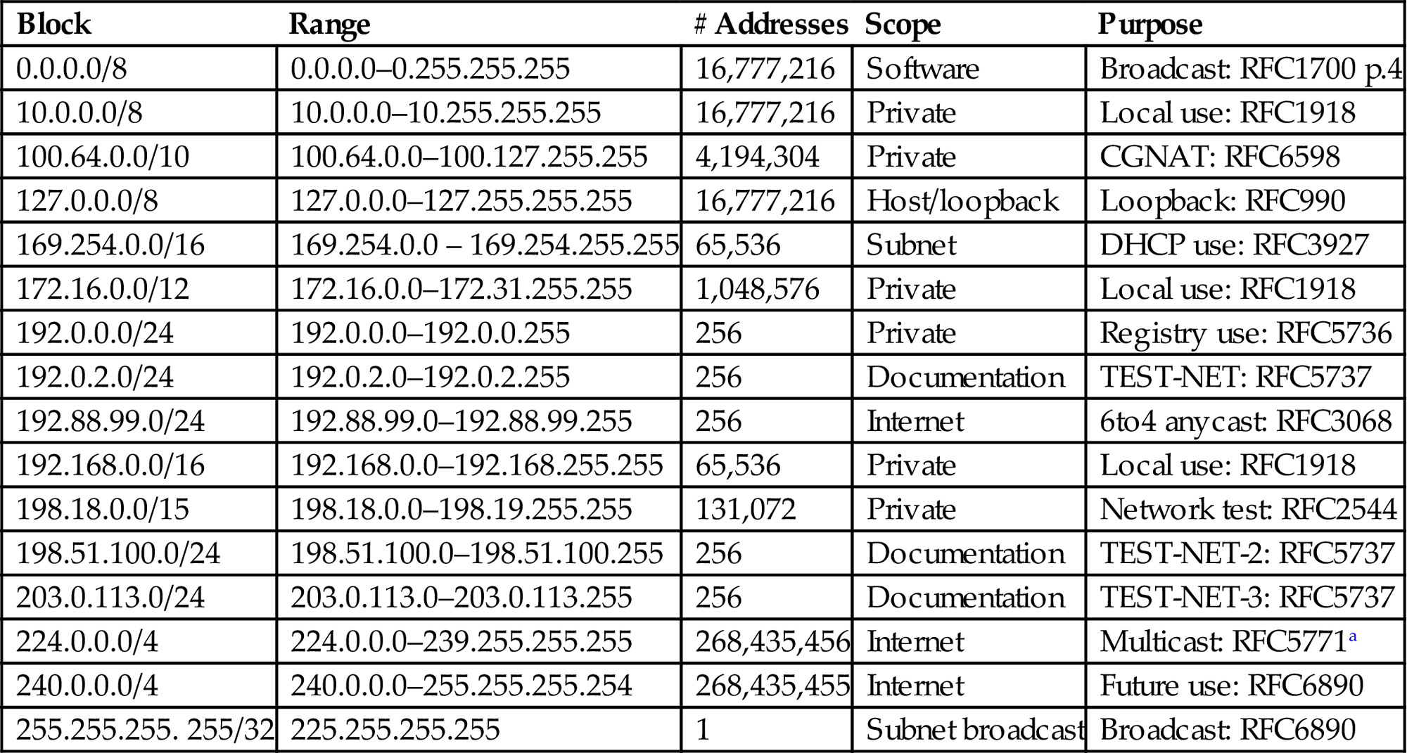
aRFC5736 reserves 233.252.0.0/24 for MCAST-TEST-NET for documentation use only.
Source: ARIN/IANA.
Table 5.7
Complete Reserved IPv6 Address Ranges
| Block | Range | # Addresses | Scope | Purpose |
| ::/128 | :: | 1 | Software | Unspecified address |
| ::1/128 | ::1 | 1 | Host | Loopback |
| ::ffff:0:0/96 | ::ffff:0.0.0.0 through ::ffff:255.255.255.255 | 232 | Software | Mapping IPv4 addresses |
| 100::/64 | 100:: through 100::ffff:ffff:ffff:ffff | 264 | Discard: RFC6666 | |
| 64:ff9b::/96 | 64:ff9b::0.0.0.0 through 64:ff9b::255.255.255.255 | 232 | Internet | IPv4/IPv6: RFC6052 |
| 2001::/32 | 2001:: through 2001::ffff:ffff:ffff:ffff:ffff:ffff | 296 | Internet | Terado tunneling |
| 2001:10::/28 | 2001:10:: through 2001:1 f:ffff:ffff:ffff:ffff:ffff:ffff | 2100 | Software | Deprecated:ORCHID |
| 2001:20::/28 | 2001:20:: through 2001:2 f:ffff:ffff:ffff:ffff:ffff:ffff | 2100 | Software | ORCHIDv2 |
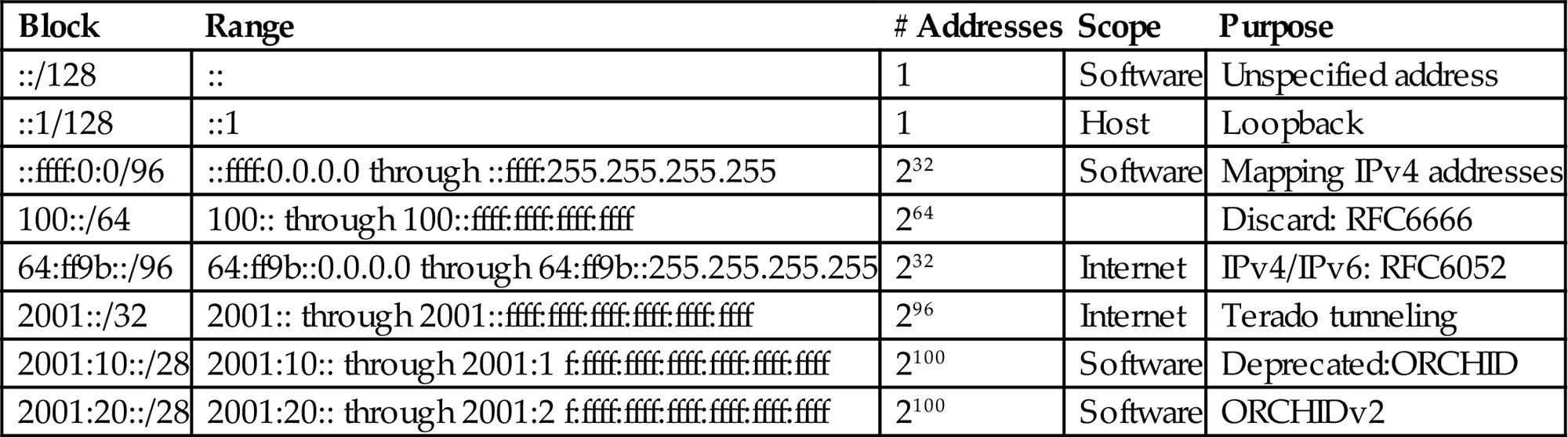
Source: ARIN/IANA.
Questions for Readers
Figure 5.9 shows some of the concepts discussed in this chapter and can be used to help you answer the following questions.
1. How many bits make up IPv4 and IPv6 addresses?
2. Which special address formats make up the IPv4 network itself and directed broadcast (all hosts on the subnet) addresses?
3. How many hosts can be configured with an IPv4 network mask of 255.255.255.240?
4. What are the differences in format and use between IPv6 link-local and private ULA-local addresses?
5. How many “double colons” (::) can appear in an IPv6 address?
