This section describes the on-disk structure of an NTFS volume, including how disk space is divided and organized into clusters, how files are organized into directories, how the actual file data and attribute information is stored on disk, and finally, how NTFS data compression works.
The structure of NTFS begins with a volume. A volume corresponds to a logical partition on a disk, and it is created when you format a disk or part of a disk for NTFS. You can also create a RAID volume that spans multiple disks by using the Windows Disk Management MMC snap-in or the diskpart (%SystemRoot%\System32\Diskpart.exe) command available from the Windows command prompt.
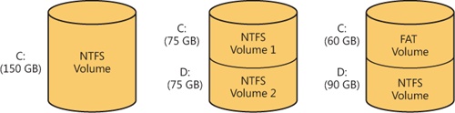
A disk can have one volume or several. NTFS handles each volume independently of the others. Three sample disk configurations for a 150-GB hard disk are illustrated in Figure 12-26.
A volume consists of a series of files plus any additional unallocated space remaining on the disk partition. In the FAT file system, a volume also contains areas specially formatted for use by the file system. An NTFS volume, however, stores all file system data, such as bitmaps and directories, and even the system bootstrap, as ordinary files.
The cluster size on an NTFS volume, or the cluster factor, is established when a user formats the volume with either the format command or the Disk Management MMC snap-in. The default cluster factor varies with the size of the volume, but it is an integral number of physical sectors, always a power of 2 (1 sector, 2 sectors, 4 sectors, 8 sectors, and so on). The cluster factor is expressed as the number of bytes in the cluster, such as 512 bytes, 1 KB, 2 KB, and so on.
Internally, NTFS refers only to clusters. (However, NTFS forms low-level volume I/O operations such that clusters are sector-aligned and have a length that is a multiple of the sector size.) NTFS uses the cluster as its unit of allocation to maintain its independence from physical sector sizes. This independence allows NTFS to efficiently support very large disks by using a larger cluster factor or to support newer disks that have a sector size other than 512 bytes. (See Chapter 9 for more information on disks with sectors larger than 512 bytes.) On a larger volume, use of a larger cluster factor can reduce fragmentation and speed allocation, at the cost of wasted disk space. (If the cluster size is 4,096, and a file is only 1,024 bytes, then 3,072 bytes are wasted. See Chapter 9 for more information on default cluster sizes.) Both the format command available from the command prompt and the Format menu option under the All Tasks option on the Action menu in the Disk Management MMC snap-in choose a default cluster factor based on the volume size, but you can override this size.
NTFS refers to physical locations on a disk by means of logical cluster numbers (LCNs). LCNs are simply the numbering of all clusters from the beginning of the volume to the end. To convert an LCN to a physical disk address, NTFS multiplies the LCN by the cluster factor to get the physical byte offset on the volume, as the disk driver interface requires. NTFS refers to the data within a file by means of virtual cluster numbers (VCNs). VCNs number the clusters belonging to a particular file from 0 through m. VCNs aren’t necessarily physically contiguous, however; they can be mapped to any number of LCNs on the volume.
In NTFS, all data stored on a volume is contained in files, including the data structures used to locate and retrieve files, the bootstrap data, and the bitmap that records the allocation state of the entire volume (the NTFS metadata). Storing everything in files allows the file system to easily locate and maintain the data, and each separate file can be protected by a security descriptor. In addition, if a particular part of the disk goes bad, NTFS can relocate the metadata files to prevent the disk from becoming inaccessible.
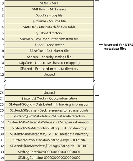
The MFT is the heart of the NTFS volume structure. The MFT is implemented as an array of file records. The size of each file record is fixed at 1 KB, regardless of cluster size. (The structure of a file record is described in the File Records section later in this chapter.) Logically, the MFT contains one record for each file on the volume, including a record for the MFT itself. In addition to the MFT, each NTFS volume includes a set of metadata files containing the information that is used to implement the file system structure. Each of these NTFS metadata files has a name that begins with a dollar sign ($), and is hidden. For example, the file name of the MFT is $MFT. The rest of the files on an NTFS volume are normal user files and directories, as shown in Figure 12-27.
Usually, each MFT record corresponds to a different file. If a file has a large number of attributes or becomes highly fragmented, however, more than one record might be needed for a single file. In such cases, the first MFT record, which stores the locations of the others, is called the base file record.
When it first accesses a volume, NTFS must mount it—that is, read metadata from the disk and construct internal data structures so that it can process application file system accesses. To mount the volume, NTFS looks in the volume boot record (VBR) (located at LCN 0), which contains a data structure call the boot parameter block (BPB), to find the physical disk address of the MFT. The MFT’s own file record is the first entry in the table; the second file record points to a file located in the middle of the disk called the MFT mirror (file name $MFTMirr) that contains a copy of the first four rows of the MFT. This partial copy of the MFT is used to locate metadata files if part of the MFT file can’t be read for some reason.
Once NTFS finds the file record for the MFT, it obtains the VCN-to-LCN mapping information in the file record’s data attribute and stores it into memory. Each run (runs are explained later in this chapter in the section Resident and Nonresident Attributes) has a VCN-to-LCN mapping and a run length because that’s all the information necessary to locate the LCN for any VCN. This mapping information tells NTFS where the runs containing the MFT are located on the disk. NTFS then processes the MFT records for several more metadata files and opens the files. Next, NTFS performs its file system recovery operation (described in the section Recovery later in this chapter), and finally, it opens its remaining metadata files. The volume is now ready for user access.
Note
For the sake of clarity, the text and diagrams in this chapter depict a run as including a VCN, an LCN, and a run length. NTFS actually compresses this information on disk into an LCN/next-VCN pair. Given a starting VCN, NTFS can determine the length of a run by subtracting the starting VCN from the next VCN.
As the system runs, NTFS writes to another important metadata file, the log file (file name $LogFile). NTFS uses the log file to record all operations that affect the NTFS volume structure, including file creation or any commands, such as copy, that alter the directory structure. The log file is used to recover an NTFS volume after a system failure and is also described in the Recovery section.
Another entry in the MFT is reserved for the root directory (also known as “\”; for example, C:\). Its file record contains an index of the files and directories stored in the root of the NTFS directory structure. When NTFS is first asked to open a file, it begins its search for the file in the root directory’s file record. After opening a file, NTFS stores the file’s MFT record number so that it can directly access the file’s MFT record when it reads and writes the file later.
NTFS records the allocation state of the volume in the bitmap file (file name $BitMap). The data attribute for the bitmap file contains a bitmap, each of whose bits represents a cluster on the volume, identifying whether the cluster is free or has been allocated to a file.
The security file (file name $Secure) stores the volume-wide security descriptor database. NTFS files and directories have individually settable security descriptors, but to conserve space, NTFS stores the settings in a common file, which allows files and directories that have the same security settings to reference the same security descriptor. In most environments, entire directory trees have the same security settings, so this optimization provides a significant saving of disk space.
Another system file, the boot file (file name $Boot), stores the Windows bootstrap code if the volume is a system volume. On non-system volumes, there is code that displays an error message on the screen if an attempt is made to boot from that volume. For the system to boot, the bootstrap code must be located at a specific disk address so that the BIOS can find it. During formatting, the format command defines this area as a file by creating a file record for it. All files are in the MFT, and all clusters are either free or allocated to a file—there are no hidden files or clusters in NTFS, although some files (metadata) are not visible to users. The boot file as well as NTFS metadata files can be individually protected by means of the security descriptors that are applied to all Windows objects. Using this “everything on the disk is a file” model also means that the bootstrap can be modified by normal file I/O, although the boot file is protected from editing.
NTFS also maintains a bad-cluster file (file name $BadClus) for recording any bad spots on the disk volume and a file known as the volume file (file name $Volume), which contains the volume name, the version of NTFS for which the volume is formatted, and a number of flag bits that indicate the state and health of the volume, such as a bit that indicates that the volume is corrupt and must be repaired by the Chkdsk utility. (The Chkdsk utility is covered in more detail later in the chapter.) The uppercase file (file name $UpCase) includes a translation table between lowercase and uppercase characters. NTFS maintains a file containing an attribute definition table (file name $AttrDef) that defines the attribute types supported on the volume and indicates whether they can be indexed, recovered during a system recovery operation, and so on.
NTFS stores several metadata files in the extensions (directory name $Extend) metadata directory, including the object identifier file (file name $ObjId), the quota file (file name $Quota), the change journal file (file name $UsnJrnl), the reparse point file (file name $Reparse), and the default resource manager directory (directory name $RmMetadata). These files store information related to extended features of NTFS. The object identifier file stores file object IDs, the quota file stores quota limit and behavior information on volumes that have quotas enabled, the change journal file records file and directory changes, and the reparse point file stores information about which files and directories on the volume include reparse point data.
The default resource manager directory contains directories related to transactional NTFS (TxF) support, including the transaction log directory (directory name $TxfLog), the transaction isolation directory (directory name $Txf), and the transaction repair directory (file name $Repair). The transaction log directory contains the TxF base log file (file name $TxfLog.blf) and any number of log container files, depending on the size of the transaction log, but it always contains at least two: one for the Kernel Transaction Manager (KTM) log stream (file name $TxfLogContainer00000000000000000001), and one for the TxF log stream (file name $TxfLogContainer00000000000000000002). The transaction log directory also contains the TxF old page stream (file name $Tops), which we’ll describe later.
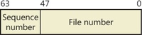
A file on an NTFS volume is identified by a 64-bit value called a file record number, which consists of a file number and a sequence number. The file number corresponds to the position of the file’s file record in the MFT minus 1 (or to the position of the base file record minus 1 if the file has more than one file record). The sequence number, which is incremented each time an MFT file record position is reused, enables NTFS to perform internal consistency checks. A file record number is illustrated in Figure 12-28.
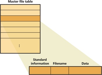
Instead of viewing a file as just a repository for textual or binary data, NTFS stores files as a collection of attribute/value pairs, one of which is the data it contains (called the unnamed data attribute). Other attributes that comprise a file include the file name, time stamp information, and possibly additional named data attributes. Figure 12-29 illustrates an MFT record for a small file.
Each file attribute is stored as a separate stream of bytes within a file. Strictly speaking, NTFS doesn’t read and write files—it reads and writes attribute streams. NTFS supplies these attribute operations: create, delete, read (byte range), and write (byte range). The read and write services normally operate on the file’s unnamed data attribute. However, a caller can specify a different data attribute by using the named data stream syntax.
Table 12-6 lists the attributes for files on an NTFS volume. (Not all attributes are present for every file.)
Table 12-6. Attributes for NTFS Files
Table 12-6 shows attribute names; however, attributes actually correspond to numeric type codes, which NTFS uses to order the attributes within a file record. The file attributes in an MFT record are ordered by these type codes (numerically in ascending order), with some attribute types appearing more than once—if a file has multiple data attributes, for example, or multiple file names. All possible attribute types (and their names) are listed in the $AttrDef metadata file.
Each attribute in a file record is identified with its attribute type code and has a value and an optional name. An attribute’s value is the byte stream composing the attribute. For example, the value of the $FILE_NAME attribute is the file’s name; the value of the $DATA attribute is whatever bytes the user stored in the file.
Most attributes never have names, although the index-related attributes and the $DATA attribute often do. Names distinguish between multiple attributes of the same type that a file can include. For example, a file that has a named data stream has two $DATA attributes: an unnamed $DATA attribute storing the default unnamed data stream and a named $DATA attribute having the name of the alternate stream and storing the named stream’s data.
Both NTFS and FAT allow each file name in a path to be as many as 255 characters long. File names can contain Unicode characters as well as multiple periods and embedded spaces. However, the FAT file system supplied with MS-DOS is limited to 8 (non-Unicode) characters for its file names, followed by a period and a 3-character extension. Figure 12-30 provides a visual representation of the different file namespaces Windows supports and shows how they intersect.
The POSIX subsystem requires the biggest namespace of all the application execution environments that Windows supports, and therefore the NTFS namespace is equivalent to the POSIX namespace. The POSIX subsystem can create names that aren’t visible to Windows and MS-DOS applications, including names with trailing periods and trailing spaces. Ordinarily, creating a file using the large POSIX namespace isn’t a problem because you would do that only if you intended the POSIX subsystem or POSIX client systems to use that file.
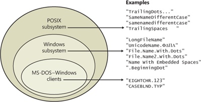
The relationship between 32-bit Windows (Windows) applications and MS-DOS and 16-bit Windows applications is a much closer one, however. The Windows area in Figure 12-30 represents file names that the Windows subsystem can create on an NTFS volume but that MS-DOS and 16-bit Windows applications can’t see. This group includes file names longer than the 8.3 format of MS-DOS names, those containing Unicode (international) characters, those with multiple period characters or a beginning period, and those with embedded spaces. When a file is created with such a name, NTFS automatically generates an alternate, MS-DOS-style file name for the file. Windows displays these short names when you use the /x option with the dir command.
The MS-DOS file names are fully functional aliases for the NTFS files and are stored in the same directory as the long file names. The MFT record for a file with an autogenerated MS-DOS file name is shown in Figure 12-31.
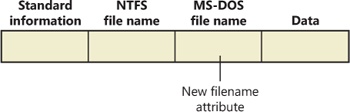
The NTFS name and the generated MS-DOS name are stored in the same file record and therefore refer to the same file. The MS-DOS name can be used to open, read from, write to, or copy the file. If a user renames the file using either the long file name or the short file name, the new name replaces both the existing names. If the new name isn’t a valid MS-DOS name, NTFS generates another MS-DOS name for the file (note that NTFS only generates MS-DOS-style file names for the first file name).
Note
Hard links are implemented in a similar way. When a hard link to a file is created, NTFS adds another file name attribute to the file’s MFT file record. The two situations differ in one regard, however. When a user deletes a file that has multiple names (hard links), the file record and the file remain in place. The file and its record are deleted only when the last file name (hard link) is deleted. If a file has both an NTFS name and an autogenerated MS-DOS name, however, a user can delete the file using either name.
Here’s the algorithm NTFS uses (the algorithm is actually implemented in the kernel function RtlGenerate8dot3Name and is also used by other drivers, such as CDFS, FAT, and third-party file systems) to generate an MS-DOS name from a long file name:
Remove from the long name any characters that are illegal in MS-DOS names, including spaces and Unicode characters. Remove preceding and trailing periods. Remove all other embedded periods, except the last one.
Truncate the string before the period (if present) to six characters (it may already be six or fewer because this algorithm is applied when any character that is illegal in MS-DOS is present in the name); if it is two or fewer characters, generate and concatenate a four-character hex checksum string. Append the string ~n (where n is a number, starting with 1, that is used to distinguish different files that truncate to the same name). Truncate the string after the period (if present) to three characters.
Put the result in uppercase letters. MS-DOS is case-insensitive, and this step guarantees that NTFS won’t generate a new name that differs from the old only in case.
If the generated name duplicates an existing name in the directory, increment the ~n string. If n is greater than 4, and a checksum was not concatenated already, truncate the string before the period to two characters and generate and concatenate a four-character hex checksum string.
Table 12-7 shows the long Windows file names from Figure 12-30 and their NTFS-generated MS-DOS versions. The current algorithm and the examples in Figure 12-30 should give you an idea of what NTFS-generated MS-DOS-style file names look like.
Note
Although not generally recommended because it can cause incompatibilities with applications that rely on them, you can disable short name generation by setting HKLM\SYSTEM\CurrentControlSet\Control\FileSystem\NtfsDisable8dot3NameCreation in the registry to a DWORD value of 1 and restarting the machine.
Table 12-7. NTFS-Generated File Names
LongFileName | LONGFI~1 |
UnicodeName.ΦDΠΛ | UNICOD~1 |
File.Name.With.Dots | FILENA~1.DOT |
File.Name2.With.Dots | FILENA~2.DOT |
File.Name3.With.Dots | FILENA~3.DOT |
File.Name4.With.Dots | FILENA~4.DOT |
File.Name5.With.Dots | FIF596~1.DOT |
Name With Embedded Spaces | NAMEWI~1 |
.BeginningDot | BEGINN~1 |
25¢.two characters | 255440~1.TWO |
© | 6E2D~1 |
If a file is small, all its attributes and their values (its data, for example) fit within the file record that describes the file. When the value of an attribute is stored in the MFT (either in the file’s main file record or an extension record located elsewhere within the MFT), the attribute is called a resident attribute. (In Figure 12-31, for example, all attributes are resident.) Several attributes are defined as always being resident so that NTFS can locate nonresident attributes. The standard information and index root attributes are always resident, for example.
Each attribute begins with a standard header containing information about the attribute, information that NTFS uses to manage the attributes in a generic way. The header, which is always resident, records whether the attribute’s value is resident or nonresident. For resident attributes, the header also contains the offset from the header to the attribute’s value and the length of the attribute’s value, as Figure 12-32 illustrates for the filename attribute.
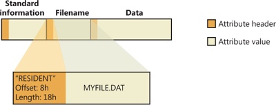
When an attribute’s value is stored directly in the MFT, the time it takes NTFS to access the value is greatly reduced. Instead of looking up a file in a table and then reading a succession of allocation units to find the file’s data (as the FAT file system does, for example), NTFS accesses the disk once and retrieves the data immediately.
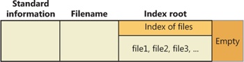
The attributes for a small directory, as well as for a small file, can be resident in the MFT, as Figure 12-33 shows. For a small directory, the index root attribute contains an index (organized as a B-tree) of file record numbers for the files (and the subdirectories) within the directory.
Of course, many files and directories can’t be squeezed into a 1-KB, fixed-size MFT record. If a particular attribute’s value, such as a file’s data attribute, is too large to be contained in an MFT file record, NTFS allocates clusters for the attribute’s value outside the MFT. A contiguous group of clusters is called a run (or an extent). If the attribute’s value later grows (if a user appends data to the file, for example), NTFS allocates another run for the additional data. Attributes whose values are stored in runs (rather than within the MFT) are called nonresident attributes. The file system decides whether a particular attribute is resident or nonresident; the location of the data is transparent to the process accessing it.
When an attribute is nonresident, as the data attribute for a large file will certainly be, its header contains the information NTFS needs to locate the attribute’s value on the disk. Figure 12-34 shows a nonresident data attribute stored in two runs.
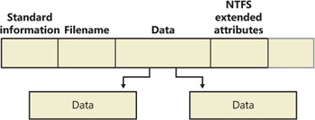
Among the standard attributes, only those that can grow can be nonresident. For files, the attributes that can grow are the data and the attribute list (not shown in Figure 12-34). The standard information and filename attributes are always resident.
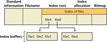
A large directory can also have nonresident attributes (or parts of attributes), as Figure 12-35 shows. In this example, the MFT file record doesn’t have enough room to store the B-tree that contains the index of files that are within this large directory. A part of the index is stored in the index root attribute, and the rest of the index is stored in nonresident runs called index allocations. The index root, index allocation, and bitmap attributes are shown here in a simplified form. They are described in more detail in the next section. The standard information and filename attributes are always resident. The header and at least part of the value of the index root attribute are also resident for directories.
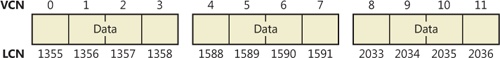
When an attribute’s value can’t fit in an MFT file record and separate allocations are needed, NTFS keeps track of the runs by means of VCN-to-LCN mapping pairs. LCNs represent the sequence of clusters on an entire volume from 0 through n. VCNs number the clusters belonging to a particular file from 0 through m. For example, the clusters in the runs of a nonresident data attribute are numbered as shown in Figure 12-36.
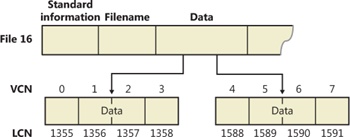
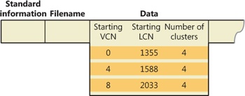
If this file had more than two runs, the numbering of the third run would start with VCN 8. As Figure 12-37 shows, the data attribute header contains VCN-to-LCN mappings for the two runs here, which allows NTFS to easily find the allocations on the disk.
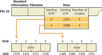
Although Figure 12-36 shows just data runs, other attributes can be stored in runs if there isn’t enough room in the MFT file record to contain them. And if a particular file has too many attributes to fit in the MFT record, a second MFT record is used to contain the additional attributes (or attribute headers for nonresident attributes). In this case, an attribute called the attribute list is added. The attribute list attribute contains the name and type code of each of the file’s attributes and the file number of the MFT record where the attribute is located. The attribute list attribute is provided for those cases where all of a file’s attributes will not fit within the file’s file record or when a file grows so large or so fragmented that a single MFT record can’t contain the multitude of VCN-to-LCN mappings needed to find all its runs. Files with more than 200 runs typically require an attribute list. In summary, attribute headers are always contained within file records in the MFT, but an attribute’s value may be located outside the MFT in one or more extents.
NTFS supports compression on a per-file, per-directory, or per-volume basis using a variant of the LZ77 algorithm, known as LZNT1. (NTFS compression is performed only on user data, not file system metadata.) You can tell whether a volume is compressed by using the Windows GetVolumeInformation function. To retrieve the actual compressed size of a file, use the Windows GetCompressedFileSize function. Finally, to examine or change the compression setting for a file or directory, use the Windows DeviceIoControl function. (See the FSCTL_GET_COMPRESSION and FSCTL_SET_COMPRESSION file system control codes.) Keep in mind that although setting a file’s compression state compresses (or decompresses) the file right away, setting a directory’s or volume’s compression state doesn’t cause any immediate compression or decompression. Instead, setting a directory’s or volume’s compression state sets a default compression state that will be given to all newly created files and subdirectories within that directory or volume (although, if you were to set directory compression using the directory’s property page within Explorer, the contents of the entire directory tree will be compressed immediately).
The following section introduces NTFS compression by examining the simple case of compressing sparse data. The subsequent sections extend the discussion to the compression of ordinary files and sparse files.
Sparse data is often large but contains only a small amount of nonzero data relative to its size. A sparse matrix is one example of sparse data. As described earlier, NTFS uses VCNs, from 0 through m, to enumerate the clusters of a file. Each VCN maps to a corresponding LCN, which identifies the disk location of the cluster. Figure 12-38 illustrates the runs (disk allocations) of a normal, noncompressed file, including its VCNs and the LCNs they map to.
This file is stored in three runs, each of which is 4 clusters long, for a total of 12 clusters. Figure 12-39 shows the MFT record for this file. As described earlier, to save space the MFT record’s data attribute, which contains VCN-to-LCN mappings, records only one mapping for each run, rather than one for each cluster. Notice, however, that each VCN from 0 through 11 has a corresponding LCN associated with it. The first entry starts at VCN 0 and covers 4 clusters, the second entry starts at VCN 4 and covers 4 clusters, and so on. This entry format is typical for a noncompressed file.
When a user selects a file on an NTFS volume for compression, one NTFS compression technique is to remove long strings of zeros from the file. If the file’s data is sparse, it typically shrinks to occupy a fraction of the disk space it would otherwise require. On subsequent writes to the file, NTFS allocates space only for runs that contain nonzero data.
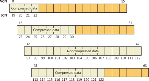
Figure 12-40 depicts the runs of a compressed file containing sparse data. Notice that certain ranges of the file’s VCNs (16–31 and 64–127) have no disk allocations.
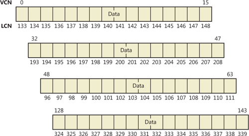
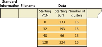
The MFT record for this compressed file omits blocks of VCNs that contain zeros and therefore have no physical storage allocated to them. The first data entry in Figure 12-41, for example, starts at VCN 0 and covers 16 clusters. The second entry jumps to VCN 32 and covers 16 clusters.
When a program reads data from a compressed file, NTFS checks the MFT record to determine whether a VCN-to-LCN mapping covers the location being read. If the program is reading from an unallocated “hole” in the file, it means that the data in that part of the file consists of zeros, so NTFS returns zeros without further accessing the disk. If a program writes nonzero data to a “hole,” NTFS quietly allocates disk space and then writes the data. This technique is very efficient for sparse file data that contains a lot of zero data.
The preceding example of compressing a sparse file is somewhat contrived. It describes “compression” for a case in which whole sections of a file were filled with zeros but the remaining data in the file wasn’t affected by the compression. The data in most files isn’t sparse, but it can still be compressed by the application of a compression algorithm.
In NTFS, users can specify compression for individual files or for all the files in a directory. (New files created in a directory marked for compression are automatically compressed—existing files must be compressed individually when programmatically enabling compression with FSCTL_SET_COMPRESSION.) When it compresses a file, NTFS divides the file’s unprocessed data into compression units 16 clusters long (equal to 8 KB for a 512-byte cluster, for example). Certain sequences of data in a file might not compress much, if at all; so for each compression unit in the file, NTFS determines whether compressing the unit will save at least 1 cluster of storage. If compressing the unit won’t free up at least 1 cluster, NTFS allocates a 16-cluster run and writes the data in that unit to disk without compressing it. If the data in a 16-cluster unit will compress to 15 or fewer clusters, NTFS allocates only the number of clusters needed to contain the compressed data and then writes it to disk. Figure 12-42 illustrates the compression of a file with four runs. The unshaded areas in this figure represent the actual storage locations that the file occupies after compression. The first, second, and fourth runs were compressed; the third run wasn’t. Even with one noncompressed run, compressing this file saved 26 clusters of disk space, or 41 percent.
Note
Although the diagrams in this chapter show contiguous LCNs, a compression unit need not be stored in physically contiguous clusters. Runs that occupy noncontiguous clusters produce slightly more complicated MFT records than the one shown in Figure 12-42.
When it writes data to a compressed file, NTFS ensures that each run begins on a virtual 16-cluster boundary. Thus the starting VCN of each run is a multiple of 16, and the runs are no longer than 16 clusters. NTFS reads and writes at least one compression unit at a time when it accesses compressed files. When it writes compressed data, however, NTFS tries to store compression units in physically contiguous locations so that it can read them all in a single I/O operation. The 16-cluster size of the NTFS compression unit was chosen to reduce internal fragmentation: the larger the compression unit, the less the overall disk space needed to store the data. This 16-cluster compression unit size represents a trade-off between producing smaller compressed files and slowing read operations for programs that randomly access files. The equivalent of 16 clusters must be decompressed for each cache miss. (A cache miss is more likely to occur during random file access.) Figure 12-43 shows the MFT record for the compressed file shown in Figure 12-42.

One difference between this compressed file and the earlier example of a compressed file containing sparse data is that three of the compressed runs in this file are less than 16 clusters long. Reading this information from a file’s MFT file record enables NTFS to know whether data in the file is compressed. Any run shorter than 16 clusters contains compressed data that NTFS must decompress when it first reads the data into the cache. A run that is exactly 16 clusters long doesn’t contain compressed data and therefore requires no decompression.
If the data in a run has been compressed, NTFS decompresses the data into a scratch buffer and then copies it to the caller’s buffer. NTFS also loads the decompressed data into the cache, which makes subsequent reads from the same run as fast as any other cached read. NTFS writes any updates to the file to the cache, leaving the lazy writer to compress and write the modified data to disk asynchronously. This strategy ensures that writing to a compressed file produces no more significant delay than writing to a noncompressed file would.
NTFS keeps disk allocations for a compressed file contiguous whenever possible. As the LCNs indicate, the first two runs of the compressed file shown in Figure 12-42 are physically contiguous, as are the last two. When two or more runs are contiguous, NTFS performs disk read-ahead, as it does with the data in other files. Because the reading and decompression of contiguous file data take place asynchronously before the program requests the data, subsequent read operations obtain the data directly from the cache, which greatly enhances read performance.
Sparse files (the NTFS file type, as opposed to files that consist of sparse data, described earlier) are essentially compressed files for which NTFS doesn’t apply compression to the file’s nonsparse data. However, NTFS manages the run data of a sparse file’s MFT record the same way it does for compressed files that consist of sparse and nonsparse data.
The change journal file, \$Extend\$UsnJrnl, is a sparse file in which NTFS stores records of changes to files and directories. Applications like the Windows File Replication Service (FRS) and the Windows Search service make use of the journal to respond to file and directory changes as they occur.
The journal stores change entries in the $J data stream and the maximum size of the journal in the $Max data stream. Entries are versioned and include the following information about a file or directory change:
The time of the change
The reason for the change (see Table 12-8)
The file or directory’s attributes
The file or directory’s name
The file or directory’s MFT file record number
The file record number of the file’s parent directory
The security ID
Additional information about the source of the change (a user, the FRS, and so on)
Table 12-8. Change Journal Change Reasons
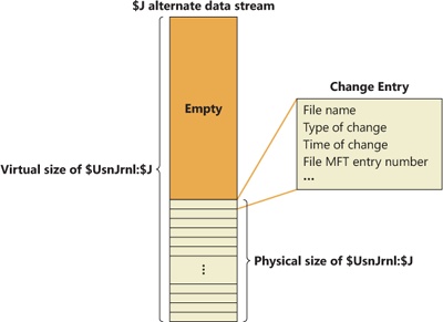
The journal is sparse so that it never overflows; when the journal’s on-disk size exceeds the maximum defined for the file, NTFS simply begins zeroing the file data that precedes the window of change information having a size equal to the maximum journal size, as shown in Figure 12-44. To prevent constant resizing when an application is continuously exceeding the journal’s size, NTFS shrinks the journal only when its size is twice an application-defined value over the maximum configured size.
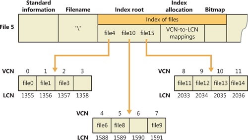
In NTFS, a file directory is simply an index of file names—that is, a collection of file names (along with their file record numbers) organized as a B-tree. To create a directory, NTFS indexes the filename attributes of the files in the directory. The MFT record for the root directory of a volume is shown in Figure 12-45.
Conceptually, an MFT entry for a directory contains in its index root attribute a sorted list of the files in the directory. For large directories, however, the file names are actually stored in 4-KB, fixed-size index buffers (which are the nonresident value of the index allocation attribute) that contain and organize the file names. Index buffers implement a B-tree data structure, which minimizes the number of disk accesses needed to find a particular file, especially for large directories. The index root attribute contains the first level of the B-tree (root subdirectories) and points to index buffers containing the next level (more subdirectories, perhaps, or files).
Figure 12-45 shows only file names in the index root attribute and the index buffers (file6, for example), but each entry in an index also contains the record number in the MFT where the file is described and time stamp and file size information for the file. NTFS duplicates the time stamps and file size information from the file’s MFT record. This technique, which is used by FAT and NTFS, requires updated information to be written in two places. Even so, it’s a significant speed optimization for directory browsing because it enables the file system to display each file’s time stamps and size without opening every file in the directory.
The index allocation attribute maps the VCNs of the index buffer runs to the LCNs that indicate where the index buffers reside on the disk, and the bitmap attribute keeps track of which VCNs in the index buffers are in use and which are free. Figure 12-45 shows one file entry per VCN (that is, per cluster), but file name entries are actually packed into each cluster. Each 4-KB index buffer will typically contain about 20 to 30 file name entries (depending on the lengths of the file names within the directory).
The B-tree data structure is a type of balanced tree that is ideal for organizing sorted data stored on a disk because it minimizes the number of disk accesses needed to find an entry. In the MFT, a directory’s index root attribute contains several file names that act as indexes into the second level of the B-tree. Each file name in the index root attribute has an optional pointer associated with it that points to an index buffer. The index buffer it points to contains file names with lexicographic values less than its own. In Figure 12-45, for example, file4 is a first-level entry in the B-tree. It points to an index buffer containing file names that are (lexicographically) less than itself—the file names file0, file1, and file3. Note that the names file1, file3, and so on that are used in this example are not literal file names but names intended to show the relative placement of files that are lexicographically ordered according to the displayed sequence.
Storing the file names in B-trees provides several benefits. Directory lookups are fast because the file names are stored in a sorted order. And when higher-level software enumerates the files in a directory, NTFS returns already-sorted names. Finally, because B-trees tend to grow wide rather than deep, NTFS’s fast lookup times don’t degrade as directories grow.
NTFS also provides general support for indexing data besides file names, and several NTFS features—including object IDs, quota tracking, and consolidated security—use indexing to manage internal data.
The B-tree indexes are a generic capability of NTFS and are used for organizing security descriptors, security IDs, object IDs, disk quota records, and reparse points. Directories are referred to as file name indexes, while other types of indexes are known as view indexes.
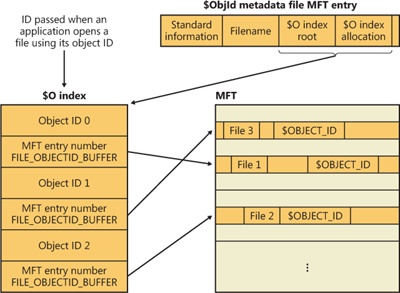
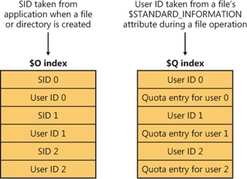
In addition to storing the object ID assigned to a file or directory in the $OBJECT_ID attribute of its MFT record, NTFS also keeps the correspondence between object IDs and their file record numbers in the $O index of the \$Extend\$ObjId metadata file. The index collates entries by object ID (which is a GUID), making it easy for NTFS to quickly locate a file based on its ID. This feature allows applications, using undocumented native API functionality, to open a file or directory using its object ID. Figure 12-46 demonstrates the correspondence of the $ObjId metadata file and $OBJECT_ID attributes in MFT records.
NTFS stores quota information in the \$Extend\$Quota metadata file, which consists of the named index root attributes $O and $Q. Figure 12-47 shows the organization of these indexes. Just as NTFS assigns each security descriptor a unique internal security ID, NTFS assigns each user a unique user ID. When an administrator defines quota information for a user, NTFS allocates a user ID that corresponds to the user’s SID. In the $O index, NTFS creates an entry that maps an SID to a user ID and sorts the index by SID; in the $Q index, NTFS creates a quota control entry. A quota control entry contains the value of the user’s quota limits, as well as the amount of disk space the user consumes on the volume.
When an application creates a file or directory, NTFS obtains the application user’s SID and looks up the associated user ID in the $O index. NTFS records the user ID in the new file or directory’s $STANDARD_INFORMATION attribute, which counts all disk space allocated to the file or directory against that user’s quota. Then NTFS looks up the quota entry in the $Q index and determines whether the new allocation causes the user to exceed his or her warning or limit threshold. When a new allocation causes the user to exceed a threshold, NTFS takes appropriate steps, such as logging an event to the System event log or not letting the user create the file or directory. As a file or directory changes size, NTFS updates the quota control entry associated with the user ID stored in the $STANDARD_INFORMATION attribute. NTFS uses the NTFS generic B-tree indexing to efficiently correlate user IDs with account SIDs and, given a user ID, to efficiently look up a user’s quota control information.
NTFS has always supported security, which lets an administrator specify which users can and can’t access individual files and directories. NTFS optimizes disk utilization for security descriptors by using a central metadata file named $Secure to store only one instance of each security descriptor on a volume.
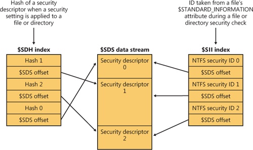
The $Secure file contains two index attributes—$SDH (Security Descriptor Hash) and $SII (Security ID Index)—and a data-stream attribute named $SDS (Security Descriptor Stream), as Figure 12-48 shows. NTFS assigns every unique security descriptor on a volume an internal NTFS security ID (not to be confused with a Windows SID, which uniquely identifies computers and user accounts) and hashes the security descriptor according to a simple hash algorithm. A hash is a potentially nonunique shorthand representation of a descriptor. Entries in the $SDH index map the security descriptor hashes to the security descriptor’s storage location within the $SDS data attribute, and the $SII index entries map NTFS security IDs to the security descriptor’s location in the $SDS data attribute.
When you apply a security descriptor to a file or directory, NTFS obtains a hash of the descriptor and looks through the $SDH index for a match. NTFS sorts the $SDH index entries according to the hash of their corresponding security descriptor and stores the entries in a B-tree. If NTFS finds a match for the descriptor in the $SDH index, NTFS locates the offset of the entry’s security descriptor from the entry’s offset value and reads the security descriptor from the $SDS attribute. If the hashes match but the security descriptors don’t, NTFS looks for another matching entry in the $SDH index. When NTFS finds a precise match, the file or directory to which you’re applying the security descriptor can reference the existing security descriptor in the $SDS attribute. NTFS makes the reference by reading the NTFS security identifier from the $SDH entry and storing it in the file or directory’s $STANDARD_INFORMATION attribute. The NTFS $STANDARD_INFORMATION attribute, which all files and directories have, stores basic information about a file, including its attributes, time stamp information, and security identifier.
If NTFS doesn’t find in the $SDH index an entry that has a security descriptor that matches the descriptor you’re applying, the descriptor you’re applying is unique to the volume and NTFS assigns the descriptor a new internal security ID. NTFS internal security IDs are 32-bit values, whereas SIDs are typically several times larger, so representing SIDs with NTFS security IDs saves space in the $STANDARD_INFORMATION attribute. NTFS then adds the security descriptor to the end of the $SDS data attribute, and it adds to the $SDH and $SII indexes entries that reference the descriptor’s offset in the $SDS data.
When an application attempts to open a file or directory, NTFS uses the $SII index to look up the file or directory’s security descriptor. NTFS reads the file or directory’s internal security ID from the MFT entry’s $STANDARD_INFORMATION attribute. It then uses the $Secure file’s $SII index to locate the ID’s entry in the $SDS data attribute. The offset into the $SDS attribute lets NTFS read the security descriptor and complete the security check. NTFS stores the 32 most recently accessed security descriptors with their $SII index entries in a cache so that it will access the $Secure file only when the $SII isn’t cached.
NTFS doesn’t delete entries in the $Secure file, even if no file or directory on a volume references the entry. Not deleting these entries doesn’t significantly decrease disk space because most volumes, even those used for long periods, have relatively few unique security descriptors.
NTFS’s use of generic B-tree indexing lets files and directories that have the same security settings efficiently share security descriptors. The $SII index lets NTFS quickly look up a security descriptor in the $Secure file while performing security checks, and the $SDH index lets NTFS quickly determine whether a security descriptor being applied to a file or directory is already stored in the $Secure file and can be shared.
As described earlier in the chapter, a reparse point is a block of up to 16 KB of application-defined reparse data and a 32-bit reparse tag that are stored in the $REPARSE_POINT attribute of a file or directory. Whenever an application creates or deletes a reparse point, NTFS updates the \$Extend\$Reparse metadata file, in which NTFS stores entries that identify the file record numbers of files and directories that contain reparse points. Storing the records in a central location enables NTFS to provide interfaces for applications to enumerate all a volume’s reparse points or just specific types of reparse points, such as mount points. (See Chapter 9 for more information on mount points.) The \$Extend\$Reparse file uses the generic B-tree indexing facility of NTFS by collating the file’s entries (in an index named $R) by reparse point tags and file record numbers.
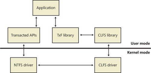
By leveraging the Kernel Transaction Manager (KTM) support in the kernel, as well as the facilities provided by the Common Log File System that were described earlier, NTFS implements a transactional model called transactional NTFS or TxF. TxF provides a set of user-mode APIs that applications can use for transacted operations on their files and directories and also a file system control (FSCTL) interface for managing its resource managers.
Note
Support for TxF was added to the NTFS driver without actually changing the format of the NTFS data structures, which is why the NTFS format version number, 3.1, is the same as it has been since Windows XP and Windows Server 2003. TxF achieves backward compatibility by reusing the attribute type ($LOGGED_UTILITY_STREAM) that was previously used only for EFS support instead of adding a new one.
The overall architecture for TxF, shown in Figure 12-49, uses several components:
Although transactional file operations are opt-in, just like the transactional registry (TxR) operations described in Chapter 4 in Part 1, TxF has an impact on regular applications that are not transaction-aware because it ensures that the transactional operations are isolated. For example, if an antivirus program is scanning a file that’s currently being modified by another application via a transacted operation, TxF must ensure that the scanner reads the pretransaction data, while applications that access the file within the transaction work with the modified data. This model is called read-committed isolation.
Read-committed isolation involves the concept of transacted writers and transacted readers. The former always view the most up-to-date version of a file, including all changes made by the transaction that is currently associated with the file. At any given time, there can be only one transacted writer for a file, which means that its write access is exclusive. Transacted readers, on the other hand, have access only to the committed version of the file at the time they open the file. They are therefore isolated from changes made by transacted writers. This allows for readers to have a consistent view of a file, even when a transacted writer commits its changes. To see the updated data, the transacted reader must open a new handle to the modified file.
Nontransacted writers, on the other hand, are prevented from opening the file by both transacted writers and transacted readers, so they cannot make changes to the file without being part of the transaction. Nontransacted readers act similarly to transacted readers in that they see only the file contents that were last committed when the file handle was open. Unlike transacted readers, however, they do not receive read-committed isolation, and as such they always receive the updated view of the latest committed version of a transacted file without having to open a new file handle. This allows non-transaction-aware applications to behave as expected.
To summarize, TxF’s read-committed isolation model has the following characteristics:
TxF implements transacted versions of the Windows file I/O APIs, which use the suffix Transacted:
Create APIs CreateDirectoryTransacted, CreateFileTransacted, CreateHardLinkTransacted, CreateSymbolicLinkTransacted
Find APIs FindFirstFileNameTransacted, FindFirstFileTransacted, FindFirstStreamTransacted
Query APIs GetCompressedFileSizeTransacted, GetFileAttributesTransacted, GetFullPathNameTransacted, GetLongPathNameTransacted
Copy and Move/Rename APIs CopyFileTransacted, MoveFileTransacted
In addition, some APIs automatically participate in transacted operations when the file handle they are passed is part of a transaction, like one created by the CreateFileTransacted API. Table 12-9 lists Windows APIs that have modified behavior when dealing with a transacted file handle.
Table 12-9. API Behavior Changed by TxF
Just like TxR uses a resource manager (RM) to keep track of transactional metadata and log files, TxF uses a default resource manager, one for each volume, to keep track of its transactional state. TxF, however, also supports additional resource managers called secondary resource managers. These resource managers can be defined by application writers and have their metadata located in any directory of the application’s choosing, defining their own transactional work units for undo, backup, restore, and redo operations. TxF uses the default resource manager for transacted APIs, and applications that use transactions with the Distributed Transaction Coordinator or the .NET Framework’s System.Transaction classes create and manage secondary TxF resource managers with TxF resource manager file system control commands. Applications can create and manage secondary RMs by using file system control codes defined for TxF, such as FSCTL_TXFS_CREATE_SECONDARY_RM, FSCTL_TXFS_START_RM, and FSCTL_TXFS_SHUTDOWN_RM. When a secondary RM is created, it must be made consistent by one or more FSCTL_TXFS_ROLLFORWARD_REDO calls followed by FSCTL_TXFS_ROLLFORWARD_UNDO, which redo and/or undo operations that were stored in the log but never committed (such as in the case of a machine crash). We’ll cover the recovery procedure for resource managers shortly. Both the default resource manager and secondary resource managers contain a number of metadata files and directories that describe their current state:
The $Txf directory, which is where files are linked when they are deleted or overwritten by transactional operations. If a file is deleted in a transaction, read-isolation rules specify that nontransacted readers should still be able to access the file before the delete operation is actually committed. This isolation is achieved by moving the transaction-deleted file into the $Txf directory. The NTFS driver will then keep track of the isolation by inserting a temporary structure in the SCB of the parent directory where the deleted file was originally located. In this way, the file will continue to show up if the parent is enumerated, and it will store the file record number, allowing the file to be opened. When the transaction is committed, NTFS deletes the temporary structure and deletes the file from the $Txf directory. On the other hand, if the transaction is rolled back, NTFS moves the file back to its original directory.
The $Tops, or TxF Old Page Stream (TOPS) file, which contains a default data stream and an alternate data stream called $T. The default stream for the TOPS file contains metadata about the resource manager, such as its GUID, its CLFS log policy, and the LSN at which recovery should start. The $T stream contains file data that is partially overwritten by a transactional writer (as opposed to a full overwrite, which would move the file into the $Txf directory). NTFS keeps a structure in memory that keeps track of which parts of a file are being modified under a transaction so that nontransacted readers can still access the noncommitted data by having their reads forwarded to $Tops:$T. When the transaction is committed or aborted, the pages are either moved from the $T stream into the original file or simply thrown out in the case of an abort.
The TxF log files, which are CLFS log files storing transaction records. For the default resource manager, these files are part of the $TxfLog directory, but secondary resource managers can store them anywhere. TxF uses a multiplexed base log file called $TxfLog.blf. The file \$Extend\$RmMetadata\$TxfLog\$TxfLog contains two streams: the KtmLog stream used for Kernel Transaction Manager metadata records, and the TxfLog stream, which contains the TxF log records. Each stream is stored in CLFS log containers that start with $TxfLogContainer and are followed by a unique, increasing ID, such as 00000000000000000001. As the TxF log grows, more container files are created.
As described earlier, the default resource manager stores its files in the \$Extend\$RmMetadata directory on each NTFS-formatted volume on the machine.
As shown earlier in Table 12-6, TxF uses the $LOGGED_UTILITY_STREAM attribute type to store additional data for files and directories that are or have been part of a transaction. This attribute is called $TXF_DATA and contains important information that allows TxF to keep active offline data for a file part of a transaction. The attribute is permanently stored in the MFT; that is, even after the file is not part of a transaction anymore, the stream remains, for reasons we’ll explain shortly. The major components of the attribute are shown in Figure 12-50.
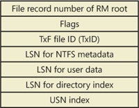
The first field shown is the file record number of the root of the resource manager responsible for the transaction associated with this file. For the default resource manager, the file record number is 5, which is the file record number for the root directory (\) in the MFT, as shown earlier in Figure 12-27. TxF needs this information when it creates an FCB for the file so that it can link it to the correct resource manager, which in turn needs to create an enlistment for the transaction when a transacted file request is received by NTFS. (For more information on enlistments and transactions, see the KTM section in Chapter 3 in Part 1.)
Another important piece of data stored in the $TXF_DATA attribute is the TxF file ID, or TxID, and this explains why $TXF_DATA attributes are never deleted. Because NTFS writes file names to its records when writing to the transaction log, it needs a way to uniquely identify files in the same directory that may have had the same name. For example, if sample.txt is deleted from a directory in a transaction and later a new file with the same name is created in the same directory (and as part of the same transaction), TxF needs a way to uniquely identify the two instances of sample.txt. This identification is provided by a 64-bit unique number, the TxID, that TxF increments when a new file (or an instance of a file) becomes part of a transaction. Because they can never be reused, TxIDs are permanent, so the $TXF_DATA attribute will never be removed from a file.
Last but not least, three CLFS LSNs are stored for each file part of a transaction. Whenever a transaction is active, such as during create, rename, or write operations, TxF writes a log record to its CLFS log. Each record is assigned an LSN, and that LSN gets written to the appropriate field in the $TXF_DATA attribute. The first LSN is used to store the log record that identifies the changes to NTFS metadata in relation to this file. For example, if the standard attributes of a file are changed as part of a transacted operation, TxF must update the relevant MFT file record, and the LSN for the log record describing the change is stored. TxF uses the second LSN when the file’s data is modified. Finally, TxF uses the third LSN when the file name index for the directory requires a change related to a transaction the file took part in, or when a directory was part of a transaction and received a TxID.
The $TXF_DATA attribute also stores internal flags that describe the state information to TxF and the index of the USN record that was applied to the file on commit. A TxF transaction can span multiple USN records that may have been partly updated by NTFS’s recovery mechanism (described shortly), so the index tells TxF how many more USN records must be applied after a recovery.
As mentioned earlier, each time a change is made to the disk because of an ongoing transaction, TxF writes a record of the change to its log. TxF uses a variety of log record types to keep track of transactional changes, but regardless of the record type, all TxF log records have a generic header that contains information identifying the type of the record, the action related to the record, the TxID that the record applies to, and the GUID of the KTM transaction that the record is associated with.
A redo record specifies how to reapply a change part of a transaction that’s already been committed to the volume if the transaction has actually never been flushed from cache to disk. An undo record, on the other hand, specifies how to reverse a change part of a transaction that hasn’t been committed at the time of a rollback. Some records are redo-only, meaning they don’t contain any equivalent undo data, while other records contain both redo and undo information.
Through the TOPS file, TxF maintains two critical pieces of data, the base LSN and the restart LSN. The base LSN determines the LSN of the first valid record in the log, while the restart LSN indicates at which LSN recovery should begin when starting the resource manager. When TxF writes a restart rec-ord, it updates these two values, indicating that changes have been made to the volume and flushed out to disk—meaning that the file system is fully consistent up to the new restart LSN.
TxF also writes compensating log records, or CLRs. These records store the actions that are being performed during transaction rollback (explained next). They’re primarily used to store the undo-next LSN, which allows the recovery process to avoid repeated undo operations by bypassing undo records that have already been processed, a situation that can happen if the system fails during the recovery phase and has already performed part of the undo pass. Finally, TxF also deals with prepare records, abort records, and commit records, which describe the state of the KTM transactions related to TxF.
When a resource manager starts because of an FSCTL_TXFS_START_RM call (or, for the default resource manager, as soon as the volume is mounted), TxF runs the recovery process. It reads the TOPS file to determine the restart LSN, where the recovery process should start, and then reads each record forward through the log (called the redo pass). As each record is being processed, TxF opens the file referenced by the record and compares the LSN in the $TXF_DATA attribute with the LSN in the record. If the LSN stored in the attribute is greater than or equal to the LSN of the log record, the action is not applied because the on-disk copy of the file is as new or newer than that of the log record action. If the LSN is not greater than or equal to the LSN in the record, the log contains information about the file that was never written to the file itself. In this case, TxF applies whichever action was recorded in the log record and updates the LSN in the $TXF_DATA attribute with the LSN from the record.
As TxF is processing its redo pass, it builds its transaction table, which describes the operations that it has completed; if it encounters an abort or commit record along the way, TxF discards the related transactions. By the end of the redo pass, TxF parses the final transaction table and connects to the KTM to see whether the KTM recorded a commit or an abort for the transactions. (KTM stores this information in the KtmLog stream of the TxF multiplexed log, as explained earlier.)
After TxF has finished communicating with the KTM, it looks at any leftover transactions in the transaction table and begins the undo pass. In the undo pass, TxF aborts all the remaining transactions in the transaction table by traversing each transaction’s undo LSN chain and applying the undo action for each log record. At the end of the undo pass, the resource manager is consistent and initialized.
This process is very similar to the log file service’s recovery procedure, which is described later in more detail. You should refer to this description for a complete picture of the standard transactional recovery mechanisms.