Chapter 5
The Cisco Digital Network Architecture Blueprint
So far this book has introduced the Cisco Digital Network Architecture philosophy and principles, in particular the fundamental goal of fully aligning your enterprise networks with the intent of your business operations. Chapter 4, “Introducing the Cisco Digital Network Architecture,” introduced and defined the Cisco DNA building blocks at a high level, outlining their main purpose from a functional perspective and the relationships between each architectural component. This chapter provides further details on each of the building blocks, unpeeling the architectural “onion” to the next level of detail. This chapter covers the following:
The Cisco DNA service definition in detail, intensifying the role of the enterprise network to connect users, applications, and devices to each other, and how policy is tightly coupled to a Cisco DNA service
Details behind the Cisco DNA infrastructure, illustrating how segmentation is realized, as well as highlighting the role of supporting network functions such as Domain Name Service (DNS), Dynamic Host Configuration Protocol (DHCP), network address translation (NAT), firewalls, etc.
The concepts of domains, scopes, and fabrics to provide structure in Cisco DNA
The role of controllers in Cisco DNA to abstract the network infrastructure and to drive policy into the network
The link between business intent and the Cisco DNA network services, providing functionality to define abstracted Cisco DNA services at a business level and automating the instantiation of these services based on orchestration to the Cisco DNA controller layer
Further insights into how operational data is continuously extracted from the network, exploring the different data collection mechanisms available in Cisco DNA and explaining how telemetry and analytics offer meaningful and timely insights into Cisco DNA network state and operations
This chapter revisits the importance of the cloud in Cisco DNA to offer truly location-agnostic network functions. It expands on the role of the cloud to host applications, the Cisco DNA analytics platforms, and even the Cisco DNA automation layer.
Cisco DNA Services
The fundamental purpose of an enterprise network is to connect applications—application clients run on your notebook, tablet, or smartphone and connect to application servers in your enterprise data center. Applications may run in a sensor, such as a connected thermometer, alarm system, or a card reader, and connect to their peer applications operated by a partner. They may run in your data center and connect to a partner’s applications. The role of the Cisco DNA-enabled network is to enable IP traffic to flow between any of those application pairs, regardless of who has operational responsibility for the devices or applications (the devices may be operated by your IT department, your employees, your partners, or even your customers).
Such application flows may become very sophisticated! Think about a Cisco Webex conference between your engineers, partners, and customers, connecting from worldwide locations. The connectivity between the Cisco Webex application clients is multipoint across the globe, most likely consumed on a myriad of devices ranging from PCs and notebooks to Apple iPhones/iPads and Android devices. Low-bandwidth voice streams and high-bandwidth video streams have to be synchronized and transmitted in real time. Some of the participants may be connected while being mobile in a car or train.
It’s such applications that define your digitalized business, and the Cisco DNA-enabled network makes it real. Figure 5-1 illustrates this relationship between the Cisco DNA network and applications that run in a variety of host devices. The network provides the connectivity of applications that are identified, for example, by an application ID or an IP port number. The devices that the applications run on can be associated with an operator—whether that is your IT department, an employee, or a customer—and thus the device too can be identified by a user or operator ID and an endpoint type. It is the applications running on the devices that become the consumers of the Cisco DNA network services. Cisco DNA services are defined as “those services that are offered to users, devices, and applications, consisting of transport in association with policies.” A Cisco DNA service has two main subcomponents:
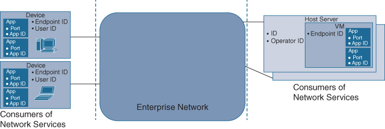
Transport services define how traffic is forwarded through the network.
Policies define how traffic is treated by the network.
From the perspective of the Cisco DNA network operator, it is useful to also differentiate between applications that are running on a particular device and applications that are under the control of a particular user (e.g., an employee), in particular because Cisco DNA is shifting toward policy-based networking. You may want to associate an access policy with a particular device type, in which case you would be interested in the set of all devices on the network of that type. Alternatively, you may want to associate a policy with a particular user or group of users, for example, to ensure that they can communicate with a particular application.
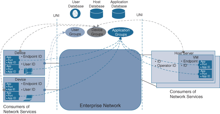
The Cisco DNA network therefore has to be aware of the users, applications, and devices connecting to it in order to deliver a transport service between them. Or, to be more precise, the network has to become aware of groupings of users, applications, and devices. For most enterprise networks, expressing the relationship between users, applications, and devices at the individual singleton level is impractical and simply not scalable. Instead, applications, users, and devices are typically grouped. The service that the network delivers for connectivity is typically associated with groups of applications, users, or devices. In the special case that an individual application, user, or device needs to be singled out, a group with that single member can be created and policy can be applied to it.
Figure 5-2 illustrates this user, application, and device awareness in Cisco DNA. Respective databases track users, devices, and applications or groupings, which allows you as a network operator to associate a Cisco DNA service between such groupings. These databases are populated in Cisco DNA by various means. For example, Cisco Identity Services Engine (ISE) is used to track users. Application registries are interfaced with to track applications. And, of course, you always have the option to explicitly create awareness of users, applications, and devices using an API or GUI.
The following subsections elaborate on the two parts of the Cisco DNA service: transport and policy.
Cisco DNA Services—Transport
The transport aspect of the Cisco DNA service definition highlights the fact that the primary purpose of offering a Cisco DNA service is to provide a communication path through the network between two or more users, applications, or devices (or groups).
At the network level, Cisco DNA service transport starts at an access interface (the ingress), which is either a physical interface or a logical interface. This ingress interface accepts IP packets as part of the service, and then ensures that the packets are transmitted to the remote end(s) of the service for delivery to the connected users, devices, or applications. The Cisco DNA network uses routing and switching as forwarding mechanisms. The Cisco DNA network may implement routing and switching to establish the path between ingress and egress. The transport may be based on a unicast service in the case where two endpoints are connected. Alternatively, the transport may be based on multicast if the relationship between the endpoints is point-to-multipoint. At the egress, the IP packets are then delivered to the recipients as part of the service.
The establishment of such communication paths in Cisco DNA may require support from additional functions. For example, network functions such as NAT, DHCP, Locator/ID Separation Protocol (LISP) Map Servers/Map Resolvers, or DNS may also come into play at the transport level to establish the communication path.
Both ingress and egress interfaces are defined by a user-to-network interface (UNI) to delineate the endpoint(s) of the Cisco DNA service. The UNI is the demarcation point of a Cisco DNA service between the Cisco DNA network and the users, applications, or devices (the “consumers”).
Cisco DNA Services—Policy
The second part of a Cisco DNA service are the policies associated with the service. The Cisco DNA service policies describe how traffic that is associated with the service is treated by the network. For example, the service may be restricted to only certain types of traffic, and thus the associated policy may be to filter out unwanted traffic. Alternatively, the Cisco DNA service may be considered business critical, and thus the network has to ensure that this criticality is implemented from the ingress to the egress (for example, by associating the Cisco DNA service with high-priority queueing).
Policies in a Cisco DNA service fall into one of three categories:
Access and security policies
Transport handling policies
Reporting policies
First, security policies govern all security aspects of the Cisco DNA service, such as which traffic can access the service. Access may be restricted to certain users, applications, or devices as described by a filter. All other nonconforming users, applications, or devices are restricted. The UNI previously described provides the demarcation point where such access policies are enforced. Traffic may then be segmented into virtual local area networks (VLAN) or virtual private networks (VPN) to ensure traffic separation between different user or application groups. Another example of a security policy that is associated with a Cisco DNA service is one that specifics its encryption level. For highly confidential Cisco DNA services, the security policy may require strong encryption end to end, preventing any unauthorized recipients to decipher the communication. Commonly, encryption is required as the service traverses untrusted devices (e.g., if a service provider network is used on the path from ingress to egress). For public Cisco DNA services, the security policy might not require encryption, allowing IP packets to be sent in the clear.
Second, transport handling policies govern how the IP packets are treated by the network from a transport perspective. These policies allow the network to manipulate the IP packet flow—for example, by applying compression, caching, adding metadata, or prioritizing on the forwarding path. Such policies may be critical to meet the service-level agreement (SLA) requirements associated with a Cisco DNA service, and hence to fulfill the right business intent.
Finally, reporting policies govern what data is collected for the IP flows of a Cisco DNA service. For some services, simple packet counts suffice. For other service, more stringent reporting is required, ensuring that full Cisco IOS NetFlow records, for example, are collected at every hop. Another example of a reporting policy is to duplicate/span the IP flows associated with a service based on an event trigger. For example, when an anomaly is detected on a particular port, such a duplication can be instantiated in the network to investigate the anomaly with an intrusion detection/prevention system (IDS/IPS). The IP packet flow associated with the Cisco DNA service is copied to the IDS/IPS, which performs a detailed anomaly detection without affecting the original packet flow.
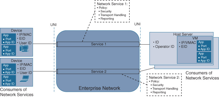
Multiple policies can be applied to a Cisco DNA service, as depicted in Figure 5-3. The figure illustrates two examples of two-endpoint Cisco DNA services, where the ingress into each Cisco DNA service is at the UNI. Each Cisco DNA service may be associated with different security, transport handling, and reporting policies. Note that traffic associated with a Cisco DNA service is inherently assumed to be bidirectional, and so the network has to ensure that the policies associated with a Cisco DNA service in each direction align.
Relationship Between Cisco DNA Policies and Business Intent
Let’s elaborate on the relationship between Cisco DNA policies and business intent in more detail. Recall that the main purpose of explicitly associating policy as a component of a Cisco DNA service is to ensure that the network fulfills the business intent, fully aligning with the business objectives.
Intent and policies can be expressed in various ways: an operator of a network element may express an access policy with a specific CLI command. An operator of the Cisco DNA service may express the access policy in more abstracted form, as a relationship between groups of users, applications, or devices, utilizing a generic syntax rather than a device-specific CLI.
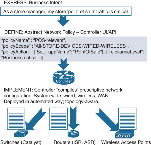
This is where the service definition and orchestration component and the controller component of Cisco DNA come into play. Each offers a level of abstraction. The relationship between the business intent and a Cisco DNA service may be specified at an abstract level in Cisco DNA’s service definition and orchestration building block. The business intent may be expressed at this level as, for example, “as a store manager, my store’s point-of-sale traffic is business critical.” Such a level of abstraction is helpful to align the Cisco DNA-enabled network with the business objectives.
The abstracted expression of business intent must be implemented in the various network elements and functions—and this is the role of the Cisco DNA controller component. As introduced in Chapter 4, the controllers provide an abstraction level of the network elements and functions, and this can be leveraged to instantiate policy. In Cisco DNA, the controller takes on the responsibility of “translating” or “mapping” the abstracted expressions of intent into device-specific configurations. The controllers may also have an abstracted notion of the Cisco DNA policy, likely with additional details and using a syntax that facilitates the ultimate instantiation of the Cisco DNA policy.
This relationship between business intent, Cisco DNA policies, and ultimate device configurations is illustrated in Figure 5-4.
Now that we’ve covered the concept of a Cisco DNA service as consumed by users, applications, or devices, we’ll elaborate on the structure of the Cisco DNA enterprise network in the subsequent sections.
Cisco DNA Infrastructure
Perhaps the most fundamental building block in a Cisco DNA-enabled network is the infrastructure. It consists of both physical and virtual network functions that are connected with each other to offer Cisco DNA services to users, applications, and devices. These functions are categorized as follows:
Transport functions: Functions that participate in forwarding IP flows associated with Cisco DNA services from ingress to egress
Supporting network functions: Functions that assist in the establishment of a forwarding path for a Cisco DNA service, as well as all functions that may manipulate the packet flows for the purpose of implementing Cisco DNA service policies
Fabrics: Functions that enable logical overlays to be built on top of a programmable underlay network with the support of a controller.
This section elaborates on the Cisco DNA infrastructure components, highlighting their functional role in the architecture, as well as the relationships between components.
Transport Functions
The transport functions in a Cisco DNA-enabled network are provided by both physical network elements (such as routers and switches) and virtualized network functions (VNF). The principal functional roles these elements play in the architecture are
Network access: The transport infrastructure provides the mechanisms for devices to access the network. This may be in the form of a dedicated physical port on an access switch. Access may be wireless based on wireless access points or other radio technologies. Regardless, devices are associated with either a physical or logical interface that represents the demarcation point of the network, and is specified by the UNI.
Policy enforcement: In Cisco DNA, any device (and by implication, the applications that run on the device) seeking to consume a Cisco DNA service must traverse such a UNI. The UNI is a construct to enforce policy, even if this policy simply states “allow all traffic into the network.” The Cisco DNA blueprint described here explicitly represents policy enforcement points (PEP) to highlight that functional component in Cisco DNA where policies are enforced. In most cases, the policies associated at the UNI are more sophisticated than a simple “allow all.” As previously discussed, the Cisco DNA policies may involve additional security, traffic handling, and reporting policies. The PEPs are places where such policies are associated with a Cisco DNA service, for example, by associating an IP flow to a particular network segment, setting bits in packet headers to reflect policy aspects (think Differentiated Services Code Point [DSCP]!), or even pushing additional headers that can subsequently be used by the network to deliver according to the Cisco DNA policy.
Note that the policy enforcement may also require the IP packet flows to be manipulated within the network. If the business intent is to provide an optimized Cisco DNA service, compression and caching may be applied to the IP flows, requiring again the manipulation of the packet flow and even possible redirection to L4–L7 network functions.
Packet transport: An obvious function offered by the transport infrastructure is the transmission of packets associated with a Cisco DNA service from the ingress into the network to the egress. The transport infrastructure accepts packets across the UNI, then forwards these packets across the network, possibly traversing multiple geographically distributed network elements and functions, and finally delivers the packets to the recipient device. To do so, the Cisco DNA transport infrastructure must establish communication paths (for example, relying on well-established routing and switching mechanisms).
Note that security plays a special role in Cisco DNA. The transport infrastructure provides segmentation to delineate flows from different services. VLANs and VPN technologies provide the fundamental infrastructure here. Segmentation is complemented by encryption functions that are instantiated where required as per the Cisco DNA service policy. Finally, the IP flows associated with a Cisco DNA service can be subjected to additional security functions such as firewalls, anomaly detection, IPS/IDS, filtering, etc. The transport infrastructure provides security by design!
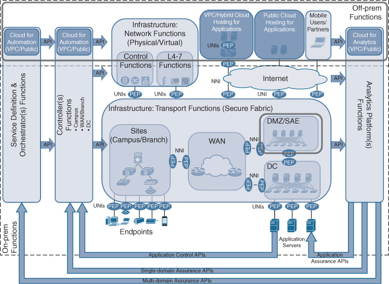
At this point it is also important to reiterate that the Cisco DNA architecture allows for network functions to be operated in the cloud. This is illustrated in Figure 5-5 by highlighting virtual private clouds (VPC). Applications may be hosted in a VPC, and a virtual routing function (e.g., using a Cisco CSR 1000V) may be used to provide the demarcation between the hosted applications and the Cisco DNA network. However, the UNI in this case is virtualized within the VPC, but exists none the less! The virtual router may be configured like any other branch router, for example with a software-defined wide-area network (SD-WAN) configuration, effectively rendering the VPC like just another branch. IP traffic generated by the cloud-hosted applications is received by a virtual interface and is still subject to a PEP representing the Cisco DNA service policy in the virtual router.
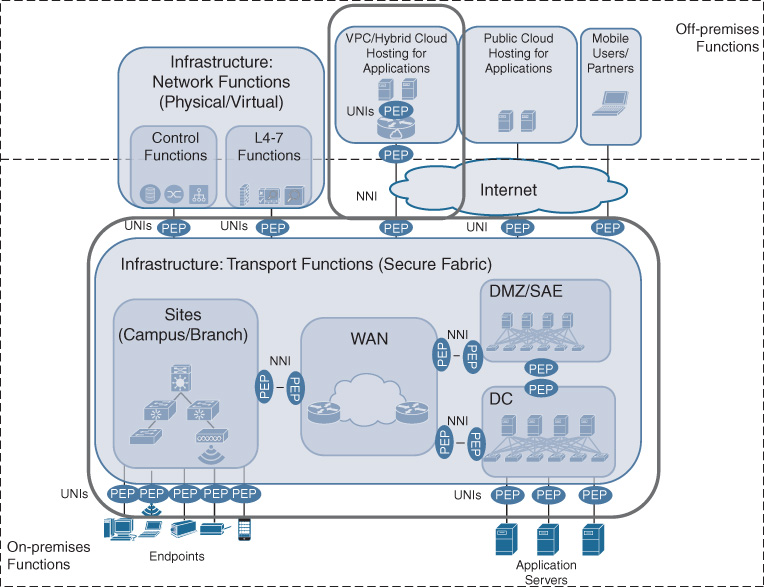
The network elements in the Cisco DNA transport infrastructure may be grouped to provide structure and to facilitate the architectural understanding behind Cisco DNA. Network elements and functions may still be grouped into WAN, data center (DC), branch, and campus sites, or demilitarized zones (DMZ), as shown in Figure 5-5. Rather than focusing on the geographic location (or place in network, PIN), however, the motivation for such groupings is technical. All of these groupings are characterized by different technical requirements.
The WAN is still assumed to be characterized by lower bandwidth rates (as compared to campus/branch connections), and often relies on service providers offering carrier services for the interconnections. Campus and branch infrastructure in Cisco DNA can be grouped into sites, consisting of both routed and switched infrastructure. Sites mainly provide access into the Cisco DNA-enabled network for endpoints and to aggregate traffic. Policy enforcement points implementing the UNI are a particular feature of sites, in particular regulating which users, applications, or devices may gain access. The network elements representing the data center are similar in nature: they provide access into the network to applications. However, in this case, the x86-based hosts running the applications are typically operated by your IT department. Furthermore, the DC infrastructure in Cisco DNA typically needs to scale far beyond branches and campuses, both in terms of number of physical hosts and in terms of bandwidth. Network elements in the DMZ need to provide particular security functionality because they connect your Cisco DNA infrastructure with the outside world.
To disambiguate the term PIN from its common meaning of personal identification number, and to emphasize the increased focus on technological characteristics rather than a geographical placement, the WAN, DC, DMZ, and sites are also referred to as “technology scopes.”
Supporting Network Functions
The transport infrastructure may rely on additional network functions to carry Cisco DNA service traffic from ingress to egress between applications. These supplementary network functions fall into two categories: control plane functions and Layer 4–Layer 7 functions, and they are realized in either a physical form factor or a virtual form factor.
Control plane functions help establish the communication paths in the transport infrastructure. For example, route reflectors or LISP Map Servers/Map Resolvers provide reachability information at the IP level and typically run in a dedicated physical appliance or as a VNF hosted on a generic x86-based server. Either way, control plane functions do not directly forward IP traffic but are essential for the transport infrastructure to achieve reachability. Other examples of supporting control plane functions are DNS servers and DHCP servers, which help endpoints to communicate in the network. The supporting Cisco DNA control plane functions, of course, complement any control plane processes that remain integrated into the transport infrastructure network elements.
The supporting Layer 4–Layer 7 network functions are typically in the data plane and, as such, may participate in manipulating the IP traffic flows of Cisco DNA services. Examples of such functions are NAT, Wide Area Application Services (WAAS), IDS/IPS, deep packet inspection (DPI), Cisco IOS NetFlow collectors, and firewalls. In most cases, such functions are instantiated in the Cisco DNA network to implement the policies for a particular consumer/producer relationship. Firewalls or IDS/IPS may be deployed to enforce a security policy. A pair of WAAS functions may be deployed to optimize the communication between two applications by using caching, data redundancy elimination, or optimizing TCP flows. Reporting policies may be enforced using DPI and Cisco IOS NetFlow collectors.
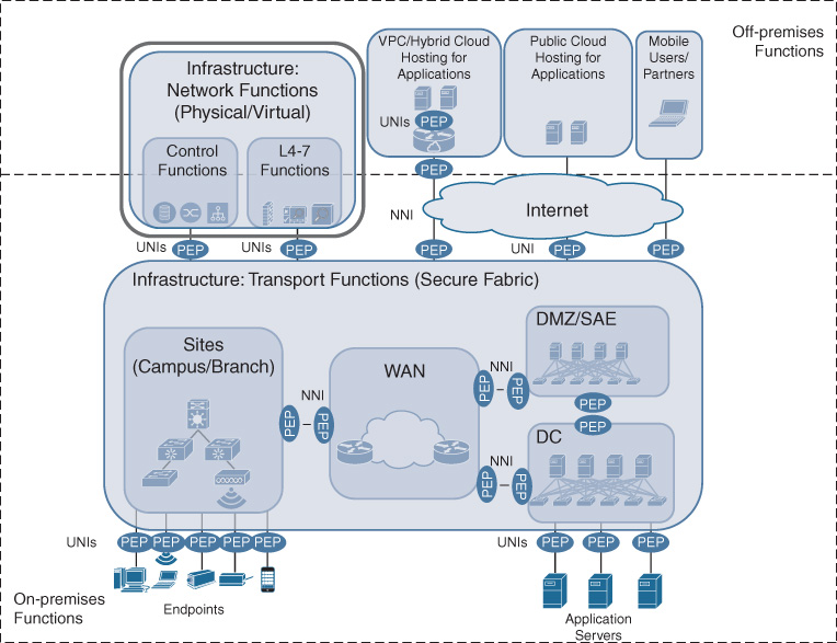
Both types of supporting network functions are treated like endpoint applications in Cisco DNA. This implies that they are connected to the transport infrastructure via a UNI and, as such, can also be associated with a PEP. Usually, reachability to such supporting network functions is universally granted, and so the access/reachability policy may simple state “allow all.” In some cases though—especially for the supporting control plane functions—encryption or logging policies may also apply. In the case of the supporting L4–L7 network functions, the Cisco DNA service traffic may also be manipulated. For example, applying WAAS to an IP flow changes the packet arrival and payload distributions. The TCP flow optimization of WAAS influences packet-sending rates (e.g., by manipulating the exponential backoff timers). WAAS data redundancy elimination may compress traffic or even serve it out of a cache.
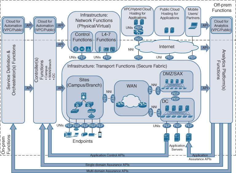
Figure 5-6 highlights this property of supporting network functions in Cisco DNA. The figure also points to the supporting network functions running either on premises or off premises. Both the control plane functions and the L4–L7 functions that may implement policy and manipulate the Cisco DNA service flows can be virtualized in the network. This also implies that these functions are already suitable to be run in a public cloud environment, a private cloud, or a hybrid cloud.
Fabrics
A key innovation in Cisco DNA on the transport infrastructure side is the use of network fabrics. Recall that in Chapter 4, the Cisco DNA fabric was defined as the infrastructure components in Cisco DNA, including a programmable underlay network, a logical overlay topology, and a controller and policy. The underlay network can be made up of both physical and virtual functions. The logical overlay networks help to deliver Cisco DNA services. The controller provides an end-to-end view of the network and an abstraction layer northbound.
Fabrics are fundamental in a Cisco DNA-enabled network for several reasons:
The explicit separation of overlays from the network infrastructure is critical to the delivery of Cisco DNA services. Overlay networks allow the creation of virtual topologies built on top of arbitrary underlay topologies. This can create alternative forwarding characteristics that may not be present in the underlay. For example, endpoint mobility, flexible and programmable topologies, or state reduction in the core are benefits of overlay networks.
In Cisco DNA, the primary overlay data plane encapsulation is based on virtual extensible LAN (VXLAN) supported by a LISP control plane. The VXLAN header offers bits to represent a scalable group tag (SGT) and a virtual network identifier (VNID). SGTs in the packet headers in Cisco DNA can be leveraged as policy anchors, using the SGT value to correlate a policy to the packet at transmission time. Traditionally, IP addresses or VLAN tags were used to implement policy as well as forwarding. These header fields are overloaded in their function, which complicated network architectures and operations. With a strict separation of the forwarding bits (Ethernet or IP headers) from the policy bits (SGTs and VNIDs), topology in Cisco DNA is cleanly separated from policy. This not only simplifies the virtual network topologies but, more importantly, allows a much expanded policy functionality—and recall, one of the key differentiators of Cisco DNA is to implement Cisco DNA service policies to reflect your business objectives!
Fabrics, and by implication all the network elements that make up the fabric, are under the governance of a single controller. This allows the controller to have a fabric-wide view of both the underlay and overlay topologies and the state of the constituent network elements. The controller can provide an abstraction layer toward northbound architecture components (notably the service definition and orchestration building block), effectively representing the network as a single construct. Note that fabrics align with a single controller, but the reverse is not necessary. A single controller can still govern multiple fabrics. The following section elaborates further on the relationships between controllers, fabrics, and domains, and their relationships to the campus and branch sites, the WAN, the DC, and the DMZ.
The network elements of a fabric are further categorized by their function into border nodes, edge nodes, and intermediary nodes. Fabric border nodes connect the fabric to external L3 networks. They are similar in functionality to traditional gateways. Fabric edge nodes are responsible for connecting endpoints, which in Cisco DNA implies that they instantiate PEPs. Fabric intermediary nodes provide IP forwarding, connecting the edge and border nodes to each other.
The fabric control plane in Cisco DNA is based on LISP. LISP maintains a tracking database of IP endpoints (hosts) to provide reachability for the overlay networks. It essentially tracks the endpoints to their fabric edge nodes, and can thus serve the location (or particular edge node) for a destination host when requested from a source host.
From an architectural perspective, it is also helpful to differentiate network elements by their relationship to the fabric. Network elements are fabric enabled, fabric attached, or fabric aware.
A device is fabric enabled if it participates in, and communicates over, the logical fabric overlay topology. In other words, it interacts with both the fabric control plane and the data plane. Examples of fabric-enabled network elements are the border, edge, and intermediary nodes.
A device is fabric attached if it participates only in the fabric control plane and does not participate in the forwarding in the overlays. An example of a fabric-attached network element is a wireless LAN controller, which falls in the previously mentioned category of Cisco DNA supporting network functions.
Finally, a device is fabric aware if it communicates over the logical fabric overlay but does not participate in the fabric control plane. For example, wireless access points may not have the ability to participate in the fabric control plane unless they support LISP.
The second part of this book is dedicated to elaborating on the infrastructure components in Cisco DNA. The chapters in that section provide much more details on fabrics in Cisco DNA, so stay tuned!
Automating Cisco DNA—Controllers
The next major building block in the Cisco DNA blueprint is the controller layer. As introduced in Chapter 4, the controller constitutes a mandatory component in Cisco DNA that is responsible for all the network elements and functions under its span. In particular, the controller executes the following functions:
Automating transport and network functions infrastructure
Maintaining a view of the infrastructure functions and connected endpoints
Instantiating and maintaining Cisco DNA services
Automating Transport and Network Functions Infrastructure
The controller assists with the automation and configuration of the transport infrastructure and its supporting network elements. For example, if the geographic reach of the network is to be extended, a new network element or virtual network function can be added to the infrastructure. Assuming the physical elements were installed, the controller then regulates the initial bring up (e.g., via plug and play) and configures the device to participate in the Cisco DNA infrastructure. Specifically, for network fabrics, the controller is responsible for creating the underlay configuration.
Maintaining a View of the Infrastructure Functions and Connected Endpoints
The controller plays a crucial role in delivering Cisco DNA services as per the business intent. A key function is thus to maintain awareness of the underlay infrastructure—i.e., the operational state and connectivity of the physical network elements. The controller is aware at any point in time about the hardware details (such as vendor, type, and linecard types) and software details (such as operating system version and firmware versions). The controller also needs to maintain awareness about user groups, application groups, and device groups that are configured in the network to enable the consumption of a Cisco DNA service.
This awareness allows the controller to have an up-to-date topological view of the infrastructure under its governance and the endpoint groups that exist in the network. Such a view is essential to offer a layer of abstraction to any north-bound Cisco DNA components (notably the service definition and orchestration layer). The Cisco DNA infrastructure under the span of a controller can be viewed as a system in itself. Any northbound building blocks do not need to know the details of the transport topology or specific information about individual network elements or functions.
Instantiating and Maintaining Cisco DNA Services
In addition to the creation (design, build, and run) of the underlay network, the controller is also responsible for the instantiation and maintenance of the Cisco DNA services. This is arguably its most important function—after all, the main pivot toward a Cisco DNA-enabled network is to align the network with the business intent, as defined by the Cisco DNA services and their associated policies.
The controller takes abstract expressions of such intent from the Cisco DNA service definition and orchestration component (discussed next) and drives the required functionality into the network elements. This implies the following:
Creating or modifying the virtual overlay networks as required by the Cisco DNA service. For example, VLANs, VXLANs, or virtual routing and forwarding (VRF) instances are created throughout the network elements in the controller domain to achieve the desired segmentation policy.
Creating or modifying PEPs in accordance with the policy. For example, if the Cisco DNA service associates a particular endpoint with a user group, the endpoint is classified at the PEP and put in the right Cisco DNA segment.
Creating or modifying any VNFs that are associated with the supporting network functions building block. For example, a service may require WAN optimization, which may be realized using a virtualized Cisco WAAS VNF. The controller in this case creates the VNF and provides its initial configuration.
Pushing relevant path information to force the traffic from a particular endpoint though a service chain as per the policy. For example, if an endpoint is associated with a policy that requires copying traffic to a traffic analysis module for reporting, the controller may push a network services header (NSH) to force the flow through a Cisco Network Analysis Module (NAM) VNF.
Figure 5-7 highlights the relationship between the controllers and the PEPs in Cisco DNA. PEPs may be instantiated throughout the network. PEPs are instantiated to regulate access to the Cisco DNA network. They are also created between different controller domains. Within a controller domain, the controller is fully aware and in charge of all PEPs to enforce the policy according to the Cisco DNA service definition.
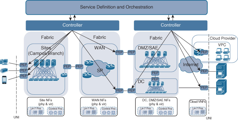
Figure 5-8 shows the relationship between the controller and the other Cisco DNA functional building blocks. The controller has interfaces via APIs into the transport infrastructure, including the supporting network functions. These APIs allow the controller to programmatically interact with the network elements, creating the dynamic programmability that was introduced in Chapter 4. The controller also has APIs with the service definition and orchestration building block. As previously described, and also illustrated in Figure 5-4, these APIs allow Cisco DNA services created at an abstract level in the service definition and orchestrator component to be automatically communicated to the one or more controller domains.
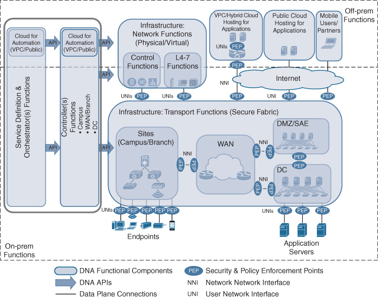
By executing these functions, the Cisco DNA controller layer simplifies the end-to-end architecture through abstractions and ensures that the network is always fully aligned with the business intent—and most importantly that the business intent is always reflected by the instantiated network policies.
Relationships in Cisco DNA: Revisiting Domains, Scopes, and Fabrics
So far this chapter has introduced the concepts of network elements that are grouped into technology scopes (WAN, sites, DC, DMZ) based on their role in the Cisco DNA transport infrastructure. Also, you’ve seen that network elements can be grouped to form Cisco DNA fabrics with a common underlay network and one or more overlays, all under the direction of a single controller. Controller domains, however, may span multiple fabrics to provide a single abstraction layer.
From an architectural perspective, it is helpful to revisit the relationships in Cisco DNA between those concepts. The architectural structures in Cisco DNA based on controller domains, technology scopes, and network fabrics help simplify the architecture.
The principal relationships between controller domains, technology scopes, and network fabrics are as follows:
The Cisco DNA transport infrastructure may consist of multiple network fabrics.
A network fabric may directly correlate to a technology scope (WAN, sites, DC, DMZ), but may also span multiple technology scopes.
Each network fabric is under the governance of a single controller.
A controller may govern multiple fabrics.
The set of network elements under the direction of the same controller defines a controller domain.
A network element may only be part of a single fabric network.
The Cisco DNA infrastructure may be governed by multiple controllers.
Figures 5-9, 5-10, and 5-11 illustrate some examples of these relationships. In Figure 5-9, network fabrics correspond to technology scopes and are each under the direction of a controller instance. Figure 5-10 shows separate fabric networks that are instantiated for the WAN, DC, DMZ, and sites. However, a single controller instance directs the operations for the WAN and site fabrics. Another controller instance governs the DMZ, DC, and VPC. Figure 5-11 on the other hand depicts a Cisco Digital Network Architecture where a single network fabric spans both the WAN and the sites. In this case, a controller instance corresponds to that fabric. The DC and DMZ scopes are again under the direction of a second controller instance.
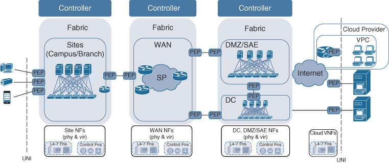
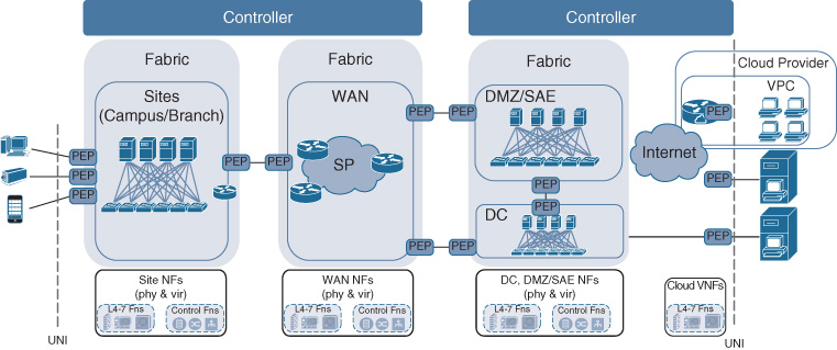
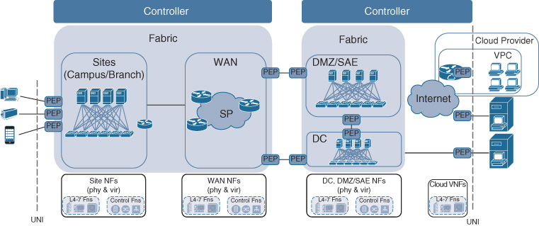
In all the examples shown in Figures 5-9 through 5-11, a network-to-network interface (NNI) specifies how Cisco DNA services are carried between the different fabric network domains. Recall that the NNI in Cisco DNA is associated with the links connecting the border network elements in the adjacent fabric networks. The NNIs connecting fabrics must thus be enforcing policy on either side of the interface, as represented by a PEP icon in each fabric. In the case where a single controller instance governs more than one fabric network, the NNI for those fabric networks is configured by that single controller. In the case where fabric networks are governed by separate controller instances, the NNI configuration in each of the fabric border nodes needs to be coordinated between the two (or more) controllers.
Note that in Figures 5-9 through 5-11, the supporting network functions are outside of the network fabrics. They are assumed not to be fabric enabled, thus connecting to the Cisco DNA infrastructure via a UNI.
The statement “a Cisco DNA infrastructure may be governed by multiple controllers” offers you as a network architect an important trade-off: how finely granular to “slice” the network elements. For certain infrastructure sizes and organizational structures, a single controller instance directing a single fabric may suffice. This avoids multiple controllers and NNIs between the respective fabric networks. On the other hand, size and organizational structure may require you to arrange the infrastructure into multiple controller domains, thus increasing the number of controller instances (even if they are of the same type or the same vendor). The more network fabrics that are operated, the larger the number of NNIs in the architecture. These may be regulated from a single controller or from different controllers. The more fragmented the Cisco DNA infrastructure into network fabrics and possibly controller domains, the more NNIs are required.
Cisco DNA Interfaces
The network architecture structure described so far intends to increase the simplicity of a Cisco DNA-enabled network. To enable a complete end-to-end transport path for the connectivity of applications between devices, the fabrics and controller domains need to connect to each other—and these interconnections are specified in form of NNIs in Cisco DNA.
The concept of a user-to-network interface was already introduced. Any user, application, or device seeking to consume a Cisco DNA service—i.e., wishing to connect to applications in the data center or cloud, or communicate with an application running on a user device—must be admitted to the Cisco DNA infrastructure via a UNI. This even holds for the supplementary network services, which are viewed as applications supporting the network operation. The UNI is tightly coupled to the notion of a policy enforcement point. As traffic from endpoints enters the network, it is associated with a particular Cisco DNA service and, by definition, the respective policies (security, transport handling, and reporting) are applied.
Between the network fabrics, however, it is the NNIs that specify how traffic traverses through the various parts of the network. NNIs always exist when two controller domains are joined. For example, an NNI dictates how the network elements under a WAN controller domain connect to the network elements under the DC controller domain.
NNIs may also exist if multiple fabrics are under the governance of a single controller, as illustrated in Figure 5-11.
Recall that in either case, the NNIs are always associated on the links connecting the two groups of network elements. This is because each network element or virtual network function is only controlled by a single controller. The NNI is not instantiated by a single border element talking to neighbors in two or more different controller domains or fabric networks. In this case, such a border element would have to be configured by the respective controllers, violating the principle stated previously that a network element can participate only in a single fabric network.
The NNIs in Cisco DNA indicate the control plane relationships as two controller domains or fabric networks that are joined. They also stipulate the data plane specifics, e.g., which frame formats are admissible to carry traffic between them.
Figure 5-12 depicts the different UNI and NNI interfaces that exist in Cisco DNA. The figure assumes that fabric networks correspond to technological scopes (WAN, DC, sites, and DMZ) with a one-to-one relationship. Endpoints (devices) on the left and applications on the right are shown to always connect via a UNI, and are associated with a single PEP building block in the diagram. Similarly, the supporting network functions at the bottom of the figure are also shown to connect to the transport infrastructure via a UNI. NNIs are placed between fabric networks to connect the various transport fabrics together, providing an end-to-end infrastructure between the applications and the endpoints. Two PEPs are shown for each NNI to emphasize the point that the NNI between fabric domains is the link, not a single network element.
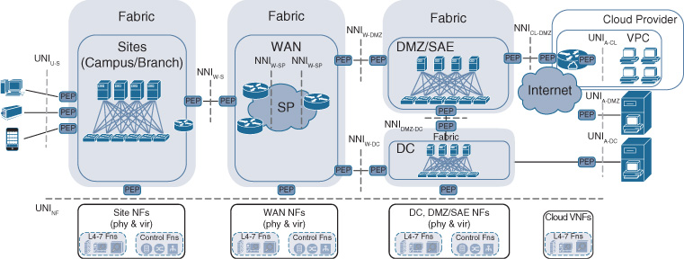
Table 5-1 lists and describes the UNI and NNI interfaces shown in Figure 5-12.
Table 5-1 UNI and NNI Interface Descriptions
Interface Label |
Description |
UNIU-S |
Interface between users or devices and site; for example, users connecting wirelessly or wired into a branch or a campus. This interface is governed by a UNI PEP. |
UNIA-CL |
Interface between applications and a cloud; for example, when the applications are hosted in a VPC and connected in the cloud environment to a network instance (VNF) for transport. This interface is governed by a UNI PEP. |
UNIA-DMZ |
Interface between applications and DMZ; for example, if a host where the applications are running is directly connected to the access switch. This interface is governed by a UNI PEP. |
UNIA-DC |
Interface between applications and the enterprise DC/private cloud; for example, when applications are running in the enterprise run DC. This interface is governed by a UNI PEP. |
UNINF |
Interface between the infrastructure/fabric and the physical or virtual network functions. This interface is governed by a UNI PEP. |
NNIW-S |
Interface between WAN and sites (campus, branch). This interface is governed by a pair of NNI PEPs. |
NNIW-SP |
Interface between the WAN and the SP. This can be a managed or unmanaged WAN service that is contracted by the enterprise from the SP to connect branches with each other or with WAN aggregation sites. This interface is governed by a pair of NNI PEPs. |
NNIW-DMZ |
Interface between the WAN and the DMZ/SAE. This interface is governed by a pair of NNI PEPs. |
NNIDMZ-DC |
Interface between the DMZ/SAE and the DC/private cloud. This interface is governed by a pair of NNI PEPs. |
NNIW-DC |
Interface between the WAN and the DC/private cloud. This interface is governed by a pair of NNI PEPs. |
NNICL-DMZ |
Interface between the cloud (VPC) and the DMZ. This interface is governed by a pair of NNI PEPs. |
Service Definition and Orchestration
So far this chapter has built up the Cisco DNA architecture from the bottom up, explaining the role of the transport infrastructure with its supporting network functions. It also has offered details on the functions of the controller, particularly its value to abstract details of the network elements to simplify the network, and to drive policy into the network in accordance with the business intent. As already alluded to, the service definition and orchestration layer defines the business intent. This section provides additional details on this component of Cisco DNA.
The service definition and orchestration building block in Cisco DNA is the component in Cisco DNA that defines the Cisco DNA services at an abstract level in accordance with the business intent, offers a presentation layer to express the business intent, and coordinates the instantiation of the Cisco DNA service instances.
Let’s look at each of these functions in turn.
First, the service definition and orchestration layer offers you as a network operator the capability to define Cisco DNA services. Recall that a Cisco DNA service expresses the relationship between applications, hosted on end-user devices or data center servers, and the associated policies. The Cisco DNA services layer thus is the place in the network where such a relationship is expressed at an abstract layer. Users, devices, and applications (or groups) are known at this level, learned from auxiliary sources such as Cisco ISE, your enterprises authentication, authorization, and accounting (AAA) servers, or application repositories, regardless of the controller domain that the endpoints are associated with. Policies are then formulated for those endpoint groups. These policies may govern the access to the network via authentication and authorization. For example, an access policy may state that users have to authenticate with a username/password combination or via IEEE 802.1X, or other authentication mechanisms. Associating a device or a user with a particular user or device group may also be stated in the access policy. The relationship between users, devices, and applications may also be governed by a policy expressed in this building block. For example, an access control policy may be specified to regulate that a user group may only communicate with one or more specified application groups. The other policy types in Cisco DNA—transport handling and reporting—are also characterized for a particular Cisco DNA service.
Table 5-2 illustrates an example of such a Cisco DNA service definition. User, application, and device groups are represented in a conceptual table, with the cell entries specifying the security (access, access control), transport handling, and reporting policies in the abstract.
Table 5-2 Example of Abstracted Policies
|
Production Servers |
Development Servers |
Internet Access |
Employee group (managed asset) |
Permit Business critical Don’t log Strong secure |
Deny |
Permit Business default |
Employee group (BYOD) |
Permit Business critical Don’t log Strong secure |
Deny |
Permit Business default |
Guests |
Deny |
Deny |
Permit Log all Business irrelevant |
Partners |
Permit Business critical Log all Strong secure |
Deny |
Deny |
Note that such policies are not necessarily expressed as pairs in all cases. A single-sided policy is thought of as a paired policy with one end being “any.” For example, upon access to the network a device always undergoes a posture assessment, regardless of the intended subsequent communication relationship.
In Cisco DNA, services are typically expressed in terms of the groups of users, applications, and devices. This makes the policies manageable by reducing the combinations of pairings. Imagine having to specify policies at the user, application, and device level in an enterprise with thousands of users, multiple thousands of devices, and hundreds of applications! Specifying policies at the individual user, application, and device level can easily result in hundreds of thousands of policies—which for the most part are identical. Grouping significantly reduces complexity to express policies and assure their compliance. However, such grouped policies do not exclude user-, application-, or device-specific policies. These can always be thought of as groups with a single member. For example, you can always create a group for the CEO of your company, and then treat your CEO as a group with one member in the policy definitions.
Second, the Cisco DNA services and definition component offers a presentation layer for the expression of such policies. The presentation layer may be in the form of a GUI that allows you to graphically express abstracted Cisco DNA services and policies. Alternatively, the presentation layer may be in the form of APIs that are called by a northbound system. In either case, the syntax to describe the services is abstracted from the network element details to achieve simplicity. An example of such a syntax was given in Figure 5-4 where the policy “point-of-sale traffic is critical” was expressed to reflect the business intent. Such abstractions are provided by the presentation layer—either built into the GUI or defined in the APIs.
Third, the service definition and orchestration layer offers the capability to drive the Cisco DNA services into the network. It coordinates the instantiation of a Cisco DNA service into the different domains/fabrics via their specific controllers, and is critical to implement the Cisco DNA services across domains. The instantiation of the Cisco DNA services needs to be coordinated between multiple controllers (hence “orchestration”). Such coordination requires that the Cisco DNA service instantiation is driven into each of the controller domains in a timely manner. It also requires a feedback loop and rollback mechanisms from the controllers to the service definition and orchestration layer. If a Cisco DNA service is instantiated across domains, the possibility of a deployment failure exists. In this case, the Cisco DNA orchestration needs to either reverse the Cisco DNA service instantiation requests in the other controller domains and report a failure, or reattempt the Cisco DNA service instantiation in the controller domain where the instantiation failed, possibly with different parameters.
The service definition and orchestration component offers the capability to define and instantiate end-to-end Cisco DNA services that align with your business intent by leveraging abstractions.
Figure 5-8 already illustrated the relationship between the service definition and orchestration building block and the remaining Cisco DNA architecture components. APIs ensure that the abstracted Cisco DNA services defined are automatically and consistently driven into the Cisco DNA infrastructure via the controller layer.
Relationship Between the Controllers and the Service Definition and Orchestration Component
The relationship between the Cisco DNA service definition and orchestration component and the controllers is illustrated in Figure 5-13, showing a high-level workflow interaction between these components. The Cisco DNA service definition and orchestration layer learns about all users, applications, and devices and their groupings, regardless of which controller domain these are associated with. This is achieved by either interfacing directly with the respective endpoint management repositories or learning via the controllers.
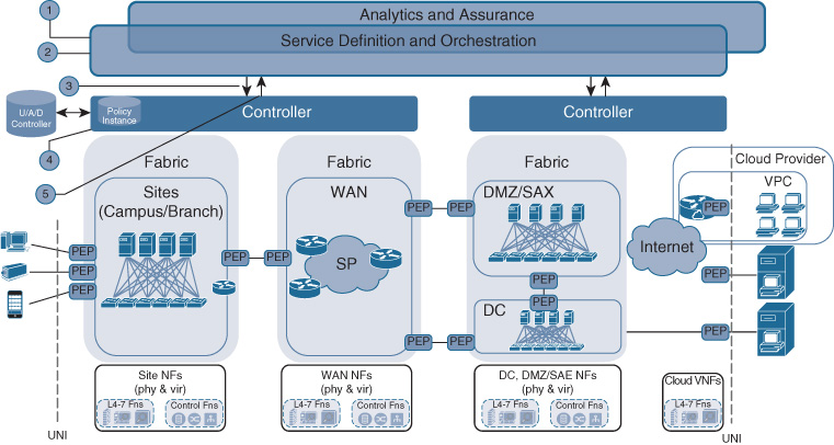
The service definition and orchestration learns about user groups, device groups, and application groups.
E.g., directly from ISE
E.g., via controllers
The service definition and orchestration defines the Cisco DNA service.
Cisco DNA services are abstract expressions of intent; for example, for application policies categorizing applications into relevant, default, or irrelevant
Access policies are abstracted into access/blocked/restricted
Cisco DNA services also contain details on monitoring
Cisco DNA services typically provide relationships between user groups, application groups, or device groups
Cisco DNA services may be scoped to a particular domain
The service definition and orchestration pushes the abstracted definition to the controller function.
Cisco DNA service scope is honored
The controller instantiates the Cisco DNA service.
Honoring Cisco DNA service scope
Controller decides how to realize the service and how to convert abstracted expressions of intent into device configurations
The controller provides feedback to the service definition and orchestration to report the outcome of the Cisco DNA service instantiation.
The service definition and orchestration layer then allows the abstract expression of a service, defining the policies (security, transport handling, and reporting) for individual endpoint groups or relationships. The Cisco DNA services may be associated with a particular scope to exclude certain controller domains. This may be helpful, for example, to prevent certain content from being accessed from outside the region, which may be the case if regulatory restrictions for applications apply.
Next, the Cisco DNA services are instantiated into the controllers by calling their respective APIs. The Cisco DNA services are typically created for the user/application/device groups at Cisco DNA service definition time. This may be independent of the time that users, devices, or applications come online. In this way, the Cisco DNA service instantiation is not tied to specific user/application/device access events in the network, which can be significantly more dynamic in nature than Cisco DNA service instantiations. The grouping of users, applications, and devices helps simplify the Cisco DNA services and makes these more manageable.
The respective Cisco DNA controllers then take the Cisco DNA service instantiation requests and drive the Cisco DNA services into the network. This implies computing the list of network elements that are required for the particular Cisco DNA service. In some cases, a VNF may need to be instantiated first to execute a particular policy function (such as WAN optimization). The controllers also translate the abstracted syntax of the Cisco DNA service that is specified at the Cisco DNA services and orchestration layer into specific device configurations. For example, a service expression that traffic is “business critical” may be translated into a priority queue configuration for some network elements, or may be translated into a class-based weighted fair queueing (CBWFQ) configuration for other network elements. Alternatively, an abstract expression of “highly confidential” may cause an IPsec configuration to be instantiated within a controller domain.
Finally, the controllers provide feedback to the Cisco DNA service definition and orchestration layer, again in form of API calls. This is important to ensure that any cross-domain Cisco DNA services are successfully instantiated in all domains. It also prevents controllers from having to communicate directly with each other, avoiding an any-to-any controller communication relationship.
Analytics Platform
The previous sections of this chapter examined how Cisco DNA services are defined and instantiated in the network. But this is only half of the Cisco DNA story—driving network functionality into the infrastructure to align with the business intent. The other half is about feedback, having the confirmation that the network has successfully instantiated a Cisco DNA service, that the Cisco DNA service aligns with the business intent. The other half is about having an instantaneous view of the state of the network whenever a user or an application manager complains about bad application performance. This section looks at the feedback mechanism that Cisco DNA offers to extract data from the network.
In Cisco DNA, the analytics building block is being defined here as “a component in Cisco DNA that gathers and normalizes operational data from the network elements and functions (data collection), exports data from network elements and functions (telemetry), facilitates the correlation of data from different sources to extract meaningful information for the purpose of reporting, optionally relying on machine learning (analysis), and provides APIs to feed the meaningful data back to the Cisco DNA controller or to other consumers of analytics data (reporting).”
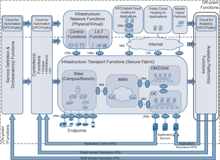
Figure 5-14 illustrates the relationship between the analytics platform and the other Cisco DNA building blocks. APIs connect all the network elements and network functions to the analytics layer (southbound APIs) to collect telemetry data from the infrastructure. Northbound APIs from the analytics communicate back to the service definition and orchestration layer, and to the controllers to automate recommended data-driven actions. This ensures that the insights derived by analytics are acted upon in the network to optimize the operation and to ensure that the Cisco DNA services are at any point in time aligning with the business intent. These northbound APIs may also be leveraged to provide feedback to applications.
Data Collection
A function of the Cisco DNA analytics platform is to collect data about the network. The data collected can come from multiple sources, be of multiple types, and be in multiple formats. In a Cisco DNA network, the principal data sources are the physical network elements and virtualized network functions. Secondary sources such as controllers or supporting network functions also provide meaningful data for the analytics platform. For example, logs from DNS or AAA servers can be exported to the analytics engine for correlation with data from other sources.
Data from network elements, VNFs, and secondary sources may be of different types:
Metrics: Data about the operational state of the network elements and VNFs, such as system counts, connection counts (e.g., packet counters), timeouts, etc.
Events: Data about incidents occurring in the network elements and VNFs, such as Syslog events, SNMP traps, event notifications, etc.
Streams: Data that is continuously collected and streamed from, for example, network sensors
The different data types collected as part of the Cisco DNA analytics platform can be in different formats and have different granularity. For example, some data may pertain to the network elements and functions, while other data may provide information about applications or users.
Data Extraction
The Cisco DNA data collection function offers the flexibility of extracting such data in multiple ways. Several telemetry mechanisms help to extract data from the network elements and functions, such as Cisco IOS NetFlow, sFlow, IPFix, or NETCONF/YANG. The collected data may be directly exported to the data processing and analytics engine. Alternatively, the data may be first stored on premises in a local collector for a site. Not all of the raw data necessarily needs to be exported to the analytics engine. Local collectors allow the normalization of data arriving in different formats. Data may also be processed using a proxy engine (distributed analytics). The latter may be beneficial to optimize the data for transport, such as to reduce duplicate event data or to preprocess data to extract summary statistics. In this way, the centralized data processing and analytics engine may not need to absorb the raw data from a large number of sources.
Note that the extracted data may need to be supplemented with additional metadata—in particular with timestamps—before exporting. Also important in the data collection process is data accuracy. Important information may be lost if metrics are collected with insufficient precision (think decimal places), or if a preprocessing engine averages out data over too long a time period and loses an important outlier event that should be reported!
Data Ingestion
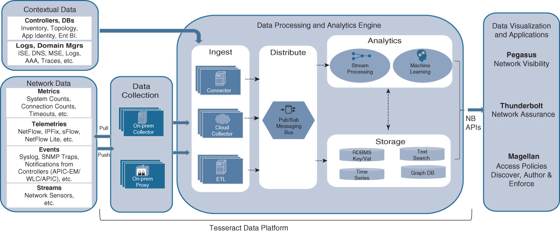
The data exported via telemetry from the network element and functions needs to be ingested into the Cisco DNA analytics engine. The analytics engine is the subcomponent of the Cisco DNA analytics platform that is responsible for analyzing the data and extracting meaningful information for various consumers of analytics data. The analytics engine has multiple constituents: a data ingestion process, one or more data processing engines, a data distribution logic (bus) to share incoming data with the various processing engines, and one or more storage repositories.
The data ingestion process is responsible for receiving the telemetry data from the various sources. For continuously streamed data, it maintains connections to the sources in the network elements, VNFs, on-premises collectors, or proxies. For data that needs to be pulled, the ingestion process implements the polling mechanism, periodically querying the sources for data.
The data distribution logic that is part of the Cisco DNA analytics platform allows the ingested data to be distributed to multiple analytics processing engines and multiple storage repositories. It implements a pub/sub messaging bus.
Multiple analytics engines process the data that was ingested and disseminated via the data distribution logic. Distributing the analytics processing load between multiple analytics algorithms allows the Cisco DNA analytics platform to scale. Also, it enables the processing to be targeted based on the type of data to be analyzed and reported. For example, an analytics process may specialize in computing information about network element data, whereas another analytics process may focus on correlating data from various sources on user or application data. Recall that data may come not only from the network elements and VNFs themselves, but also from auxiliary sources. This enables the analytics engines to correlate data from different sources and offer meaningful data, rather than just raw data, to the consumers of the analytics. Note that the analytics engines may rely on machine learning to do their job.
The data storage repositories that are part of the Cisco DNA analytics platform allow the ingested data or the post-processed data to be stored. This is extremely useful to offer time-series analysis—showing how the network, a Cisco DNA service, or a user experience evolves over time. It also allows the analytics engines to draw on historical data to make their inferences. Many machine learning algorithms that are based on artificial intelligence algorithms rely on such historical data to train the algorithms, or to continuously self-optimize the algorithms. A further functionality offered by the data storage repositories is support for text searches or keeping a database for information graphs—relationships between various kinds of objects (network topologies, user group information, policy graphs, etc.).
Data Export
The Cisco DNA analytics platform offers APIs to export the computed meaningful information to various consumers. First and foremost, analytics data can be fed back into the service definition and orchestration layer and controller layer of Cisco DNA. This is extremely useful to provide Cisco DNA service assurance: guaranteeing that the Cisco DNA services that reflect the business intent are indeed operating as designed. Alternatively, if they are not, the controllers can leverage the analytics data to automatically drive changes into the infrastructure to bring the affected Cisco DNA services back into compliance.
The analytics data also serves to provide meaningful information back to other “consumers.” A GUI, for example, can display analytics data to you as a network operator, to various levels of support staff, or even to the application owners directly. Similarly, application developers may query analytics data to optimize the behavior of their application. Think about the many applications that can leverage user location data from the network!
Figure 5-15 shows the detailed subcomponents of the Cisco DNA analytics platform previously discussed.
On-Premises and Off-Premises Agnosticism—Revisiting the Cloud
One of the key enhancements of Cisco DNA is the full inclusion and support of the cloud in the enterprise network. As introduced in the previous chapter, this inclusion comes in three main forms:
Providing the ability to extend the enterprise network into the cloud for cloud-hosted applications.
Leveraging the cloud for hosting the Cisco DNA service definition and orchestration component and the controller component
Leveraging the cloud for hosting the Cisco DNA analytics platform
Figure 5-16 illustrates the relationship between the cloud-hosted components and the Cisco DNA building blocks introduced so far. This section is revisiting the role of the cloud in Cisco DNA to provide further details on how the cloud is fully integrated into the architecture.
Application Hosting in the Cloud and the Evolution of the DMZ
As enterprise applications are increasingly hosted in the cloud, the enterprise network architecture needs to ensure that connectivity is seamless to reach those applications. The connectivity options vary by the type of cloud that is consumed.
In the case of a virtual private cloud, such as Amazon AWS or Microsoft Azure, applications are hosted on the cloud provider’s hosting infrastructure. This infrastructure may be physically shared between multiple enterprises, but it is strictly separated at a logical level to ensure privacy. From an enterprise architecture perspective, the applications are strictly separated from others and considered private.
Connectivity into a VPC environment is typically established by running a virtualized forwarding function such as a virtual router in the VPC. Such a virtualized forwarding function is often also responsible for encrypting the enterprise traffic flows across the Internet connecting the enterprise-managed Cisco DNA infrastructure to the cloud. Note that you own and control networking functionality within the VPC!
Toward the applications that are hosted in the VPC, traditional virtualization and segmentation techniques may be applied to ensure reachability.
Application hosting in a VPC is illustrated in Figure 5-16. Note that in such an architecture there are typically two types of PEPs: a PEP that regulates the access of the enterprise applications into Cisco DNA, and a PEP to enforce the policies of connecting a VPC domain to the remainder of the Cisco DNA infrastructure. The latter may, for example, postulate that traffic needs to be encrypted if the VPC is connected to the Cisco DNA DMZ across the Internet.
In the case of an application that is consumed as a service (SaaS), the connectivity of the application into the Cisco DNA architecture is typically over the Internet directly. In this case, you do not own any infrastructure or networking functions in the SaaS provider. Traffic to and from the hosted applications is secured at the application level.
SaaS traffic ingresses your Cisco DNA architecture in a gateway that is typically hosted in the DMZ. Additional security functions may be applied in the DMZ to protect your network against attacks. For example, the DMZ may be protected by a firewall. The SaaS traffic may have to traverse an application layer gateway. Functions such as intrusion prevention and intrusion detection may also be applied to protect against malicious traffic.
Note that in Figure 5-16 the SaaS and public cloud connectivity is also depicted. In this case, traffic is governed by a UNI PEP upon ingress into the Cisco DNA infrastructure.
In the case of applications being hosted in a hybrid cloud environment, they are hosted using a mix of on-premises hosts and private or even public cloud environments. A hybrid cloud is under a common orchestration platform to enable a seamless migration of your enterprise application between cloud environments. The previously described connectivity options apply to hybrid clouds as well.
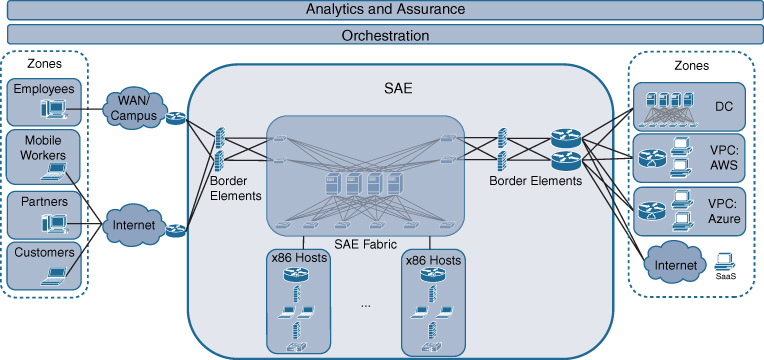
As mentioned, a DMZ is needed in the architecture as an entry point into Cisco DNA. Because cloud connectivity in Cisco DNA is vital, the DMZ architecture is significantly enhanced to provide a secure and agile exchange infrastructure (SAE). SAE evolves a traditional DMZ along multiple fronts. First, it offers a place in the Cisco DNA architecture where traffic between multiple endpoint and application groups can be exchanged. Hosting applications in the cloud increases the diversity of traffic that leaves the enterprise-managed infrastructure. Extranet partners, customers, VPC applications, SaaS applications, and any Internet traffic originating from your enterprise can now be exchanged. Second, SAE extends a traditional DMZ architecture to be fully policy-based. The policies associated with a Cisco DNA service are brought forward and extended into the SAE domain of Cisco DNA. SAE focuses particularly on security functionality, because it primarily governs the connectivity to endpoints and applications that are not hosted on enterprise-managed infrastructure. Third, SAE leverages virtualization to implement Cisco DNA policies. Using VNFs allows such functions to be deployed more dynamically and potentially with a per-Cisco DNA-service granularity. This can have significant operational benefits. Think about upgrading the software on a shared firewall: a physical firewall shared among multiple applications is harder to upgrade. All the application owners need to coordinate their upgrade windows. Virtualized, per-application firewalls can be upgraded independently!
Figure 5-17 illustrates the concept of SAE, highlighting the domain as a central connectivity point for and between employee groups, partners, customers, mobile workers, and applications sitting in the private DC, a VPC, or consumed as a service. This exchange in SAE is fully policy-based under the same service definition and orchestration component or analytics component already described.
Leveraging the Cloud for Cisco DNA Controllers and Analytics
Connectivity into the cloud for Cisco DNA is, of course, important and relevant not only for enterprise applications. The Cisco DNA control plane applications also benefit from running in the cloud—after all, the Cisco DNA service definition and orchestration component, controller component, and analytics platform are all software functions! These functions are fully cloud enabled in Cisco DNA.
In the context of the Cisco DNA control functions (service definition and orchestration, controllers, and analytics platform), the benefits of cloud computing can be applied to Cisco DNA itself! Running these functions in a VPC, for example, alleviates the need to manage your own hosting infrastructure for Cisco DNA control. The cloud provider manages the complexities of operating server and storage infrastructures, power, cooling, etc. For the analytics functions in particular, this enables flexible scale-out of the Cisco DNA control infrastructure. As more analytics engines are deployed to extract meaningful information from your Cisco DNA infrastructure, additional compute and storage is simply consumed as a service. Also, the advantages of cloud hosting from a high-availability perspective can be leveraged. Your Cisco DNA control functions are always available—the cloud providers assume the responsibility of managing hardware failures. And from a software perspective, the Cisco DNA control functions are fully cloud enabled—leveraging virtualization and containers, as well as scale-out architectures in support. Finally, running the Cisco DNA control functions in the cloud allows you to manage your Cisco DNA services and infrastructure from anywhere.
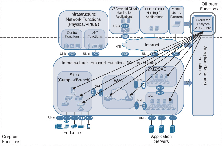
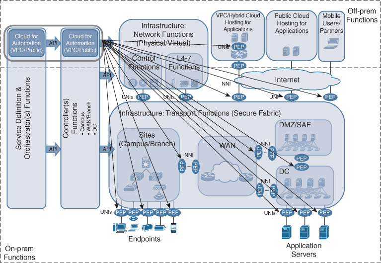
Figures 5-18 and 5-19 show how the Cisco DNA service definition and orchestration component, controller component, and analytics platform run in a cloud environment respectively. A major difference in using the cloud for Cisco DNA control arises with the traffic patterns: for Cisco DNA services, traffic is segmented in the Cisco DNA infrastructure based on the relationships between users, applications, and device groups. The traffic uses overlays to traverse the Cisco DNA network. In the case of Cisco DNA control being hosted in a cloud environment, however, the traffic must reach the Cisco DNA infrastructure and components directly. As outlined in the previous sections, API calls are binding the service definition and orchestration component to the controller component, the controller component to the network elements and network functions, or to the analytics platform. These API calls allow for the various components to behave as one system. This is highlighted in the diagrams by the example of the controllers configuring the PEPs, or the analytics platform interfacing with the network elements to extract telemetry data.
Summary
This chapter unpeeled the architectural onion another layer, looking at the architectural components of Cisco DNA in more depth. The key of Cisco DNA is to enable applications that reside in endpoints to talk to each other—regardless of whether these endpoints are operated by your IT department, by an employee, or by a partner. The Cisco DNA service not only offers the transport between these applications, but also implements your business policies to regulate the communication. The policies focus on security (authentication, access control, encryption), but also extend to govern transport handling (SLAs, quality of experience, traffic optimization) and reporting.
The Cisco DNA transport infrastructure in this blueprint consists of the traditional packet-forwarding elements arranged as a fabric. Supporting network functions provide the necessary infrastructure for the Cisco DNA control plane, as well as the capabilities to implement some of the policies required to instantiate a Cisco DNA service (e.g., firewalls, WAN optimization, etc.).
The controller layer in Cisco DNA plays a special role. Not only does this component abstract the complexities of diverse network elements and VNFs (possibly from multiple vendors), but, perhaps more importantly, the controllers offer an abstraction layer into the network, allowing Cisco DNA services (and policies in particular) to be expressed in the abstract. The controllers then perform the function of translating the abstract expression of intent into actionable device configurations, and driving these into the appropriate network elements. Controllers allow the Cisco DNA infrastructure to be structured into different controller domains, with well-defined interfaces between them.
The controllers in Cisco DNA work hand in hand with the service definition and orchestration building block, which is where Cisco DNA services are defined, expressing the relationships between users, applications, or devices. These are typically grouped in Cisco DNA for scalability. Cisco DNA services defined at this layer are expressed in a technology-abstracted syntax to facilitate the alignment with your business intent. The service definition and orchestration layer is responsible for driving the Cisco DNA services into all the different controller domains, making it the end-to-end building block. Controller domains, with their intricate knowledge of all network elements and functions, need not have a global view of the entire enterprise network. For a Cisco DNA service to be instantiated end to end across enterprise sites, the WAN, the DMZ, and various forms of the cloud, only the users, applications, and devices need to be globally known. The service definition and orchestration component in Cisco DNA thus contributes significantly to simplifying the architecture!
The analytics platform in Cisco DNA complements the mentioned building blocks to enable instantaneous and accurate information about the Cisco DNA network components. After all, one of the key goals in Cisco DNA is to guarantee that the network is at any time in full alignment with your business objectives as expressed by Cisco DNA services. Cisco DNA analytics provides the required functionality to collect various types of data from all over the network and from supporting sources, to normalize and feed this data up to the Cisco DNA analytics platform, and to correlate and run the data through multiple analytics engines to derive meaningful information. These results are then fed back into the controller and service definition and orchestration layers to deliver a closed-loop control cycle for Cisco DNA services. Alternatively, the insights derived from the analytics platform can be exposed to you as a network operator in a GUI, or to application developers who may also want to consume the data as part of their applications.
Last but not least, the Cisco DNA blueprint outlined in this chapter stresses the importance of the cloud in the architecture. Applications are assumed to run in the cloud—period. Whether the consumption model is in the form of a virtual private cloud, as a service, or a hybrid cloud, Cisco DNA services and their associated policies reach into the cloud. In case of a VPC, the Cisco DNA services are orchestrated into the cloud. In the case of SaaS or to allow access for mobile employees, customers, or partners over the Internet, the respective Cisco DNA services are instantiated in the DMZ. Due to the importance of the cloud, the DMZ is elevated in importance as a domain in Cisco DNA as a Secure Agile Exchange (SAE) point. In support of Cisco DNA services, SAE is fully policy aware and virtualized, critical to instantiate security functions on demand.
Figure 5-20 summarizes the Cisco DNA blueprint described in this chapter with all its principal components. We’ll delve into the depths of each of these components in more detail in the subsequent chapters.
