Two transformations that come up often in the OpenCV routines we have discussed—as well as in other applications you might write yourself—are the affine and perspective transformations. We first encountered these in Chapter 6. As implemented in OpenCV, these routines affect either lists of points or entire images, and they map points on one location in the image to a different location, often performing subpixel interpolation along the way. You may recall that an affine transform can produce any parallelogram from a rectangle; the perspective transform is more general and can produce any trapezoid from a rectangle.
The perspective transformation is closely related to the perspective projection. Recall that the perspective projection maps points in the three-dimensional physical world onto points on the two-dimensional image plane along a set of projection lines that all meet at a single point called the center of projection. The perspective transformation, which is a specific kind of homography, [192] relates two different images that are alternative projections of the same three-dimensional object onto two different projective planes (and thus, for nondegenerate configurations such as the plane physically intersecting the 3D object, typically to two different centers of projection).
These projective transformation-related functions were discussed in detail in Chapter 6; for convenience, we summarize them here in Table 12-1.
Table 12-1. Affine and perspective transform functions
|
Function |
Use |
|---|---|
|
|
Affine transform a list of points |
|
|
Affine transform a whole image |
|
|
Fill in affine transform matrix parameters |
|
|
Fill in affine transform matrix parameters |
|
|
Low-overhead whole image affine transform |
|
|
Perspective transform a list of points |
|
|
Perspective transform a whole image |
|
|
Fill in perspective transform matrix parameters |
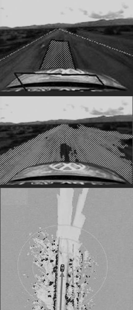
A common task in robotic navigation, typically used for planning purposes, is to convert the robot's camera view of the scene into a top-down "bird's-eye" view. In Figure 12-1, a robot's view of a scene is turned into a bird's-eye view so that it can be subsequently overlaid with an alternative representation of the world created from scanning laser range finders. Using what we've learned so far, we'll look in detail about how to use our calibrated camera to compute such a view.
Figure 12-1. Bird's-eye view: A camera on a robot car looks out at a road scene where laser range finders have identified a region of "road" in front of the car and marked it with a box (top); vision algorithms have segmented the flat, roadlike areas (center); the segmented road areas are converted to a bird's-eye view and merged with the bird's-eye view laser map (bottom)
To get a bird's-eye view, [193] we'll need our camera intrinsic and distortion matrices from the calibration routine. Just for the sake of variety, we'll read the files from disk. We put a chessboard on the floor and use that to obtain a ground plane image for a miniature robot car; we then remap that image into a bird's-eye view. The algorithm runs as follows.
Read the intrinsics and distortion models for the camera.
Find a known object on the ground plane (in this case, a chessboard). Get at least four points at subpixel accuracy.
Enter the found points into
cvGetPerspectiveTransform()(see Chapter 6) to compute the homography matrix H for the ground plane view.Use
cvWarpPerspective( )(again, see Chapter 6) with the flagsCV_INTER_LINEAR + CV_WARP_INVERSE_MAP + CV_WARP_FILL_OUTLIERSto obtain a frontal parallel (bird's-eye) view of the ground plane.
Example 12-1 shows the full working code for bird's-eye view.
Example 12-1. Bird's-eye view
//Call:
//  birds-eye board_w board_h instrinics distortion image_file
// ADJUST VIEW HEIGHT using keys 'u' up, 'd' down. ESC to quit.
//

int main(int argc, char* argv[]) {
  if(argc != 6) return -1;

  // INPUT PARAMETERS:
  //
  int       board_w    = atoi(argv[1]);
  int       board_h    = atoi(argv[2]);
  int       board_n    = board_w * board_h;
  CvSize    board_sz   = cvSize( board_w, board_h );
  CvMat*    intrinsic  = (CvMat*)cvLoad(argv[3]);
  CvMat*    distortion = (CvMat*)cvLoad(argv[4]);
  IplImage* image      = 0;
  IplImage* gray_image = 0;
  if( (image = cvLoadImage(argv[5])) == 0 ) {
    printf("Error: Couldn't load %s\n",argv[5]);
    return -1;
  }
  gray_image = cvCreateImage( cvGetSize(image), 8, 1 );
  cvCvtColor(image, gray_image, CV_BGR2GRAY );

  // UNDISTORT OUR IMAGE
  //
  IplImage* mapx = cvCreateImage( cvGetSize(image), IPL_DEPTH_32F, 1 );
  IplImage* mapy = cvCreateImage( cvGetSize(image), IPL_DEPTH_32F, 1 );
//This initializes rectification matrices
//
cvInitUndistortMap(
  intrinsic,
  distortion,
  mapx,
  mapy
);
IplImage *t = cvCloneImage(image);

// Rectify our image
//
cvRemap( t, image, mapx, mapy );

// GET THE CHESSBOARD ON THE PLANE
//
cvNamedWindow("Chessboard");
CvPoint2D32f* corners = new CvPoint2D32f[ board_n ];
int corner_count = 0;
int found = cvFindChessboardCorners(
  image,
  board_sz,
  corners,
  &corner_count,
  CV_CALIB_CB_ADAPTIVE_THRESH | CV_CALIB_CB_FILTER_QUADS
);
if(!found){
  printf("Couldn't aquire chessboard on %s, "
    "only found %d of %d corners\n",
    argv[5],corner_count,board_n
  );
  return -1;
}
//Get Subpixel accuracy on those corners:
cvFindCornerSubPix(
  gray_image,
  corners,
  corner_count,
  cvSize(11,11),
  cvSize(-1,-1),
  cvTermCriteria( CV_TERMCRIT_EPS | CV_TERMCRIT_ITER, 30, 0.1 )
);

//GET THE IMAGE AND OBJECT POINTS:
// We will choose chessboard object points as (r,c):
// (0,0), (board_w-1,0), (0,board_h-1), (board_w-1,board_h-1).
//
CvPoint2D32f objPts[4], imgPts[4];
objPts[0].x = 0;          objPts[0].y = 0;
objPts[1].x = board_w-1;  objPts[1].y = 0;
objPts[2].x = 0;          objPts[2].y = board_h-1;
objPts[3].x = board_w-1;  objPts[3].y = board_h-1;
imgPts[0]   = corners[0];
imgPts[1]   = corners[board_w-1];
imgPts[2]   = corners[(board_h-1)*board_w];
imgPts[3]   = corners[(board_h-1)*board_w + board_w-1];

// DRAW THE POINTS in order: B,G,R,YELLOW
//
cvCircle( image, cvPointFrom32f(imgPts[0]), 9, CV_RGB(0,0,255),   3);
cvCircle( image, cvPointFrom32f(imgPts[1]), 9, CV_RGB(0,255,0),   3);
cvCircle( image, cvPointFrom32f(imgPts[2]), 9, CV_RGB(255,0,0),   3);
cvCircle( image, cvPointFrom32f(imgPts[3]), 9, CV_RGB(255,255,0), 3);

// DRAW THE FOUND CHESSBOARD
//
cvDrawChessboardCorners(
  image,
  board_sz,
  corners,
  corner_count,
  found
);
cvShowImage( "Chessboard", image );

// FIND THE HOMOGRAPHY
//
CvMat *H = cvCreateMat( 3, 3, CV_32F);
cvGetPerspectiveTransform( objPts, imgPts, H);

// LET THE USER ADJUST THE Z HEIGHT OF THE VIEW
//
float Z = 25;
int key = 0;
IplImage *birds_image = cvCloneImage(image);
cvNamedWindow("Birds_Eye");

// LOOP TO ALLOW USER TO PLAY WITH HEIGHT:
//
// escape key stops
//
while(key != 27) {
  // Set the height
  //
  CV_MAT_ELEM(*H,float,2,2) = Z;

  // COMPUTE THE FRONTAL PARALLEL OR BIRD'S-EYE VIEW:
  // USING HOMOGRAPHY TO REMAP THE VIEW
  //
  cvWarpPerspective(
    image,
    birds_image,
    H,
    CV_INTER_LINEAR | CV_WARP_INVERSE_MAP | CV_WARP_FILL_OUTLIERS
  );
  cvShowImage( "Birds_Eye", birds_image );

    key = cvWaitKey();
    if(key == 'u') Z += 0.5;
    if(key == 'd') Z -= 0.5;
  }

  cvSave("H.xml",H); //We can reuse H for the same camera mounting
  return 0;
}
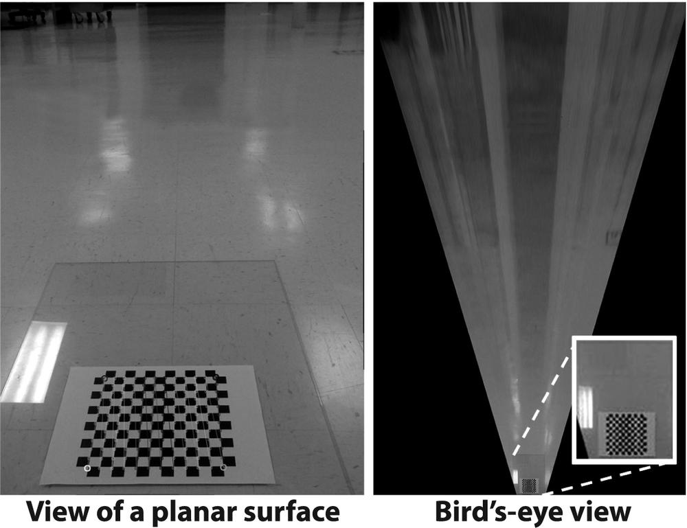
Once we have the homography matrix and the height parameter set as we wish, we could then remove the chessboard and drive the miniature car around, making a bird's-eye view video of the path, but we'll leave that as an exercise for the reader. Figure 12-2 shows the input at left and output at right for the bird's-eye view code.
[192] Recall from Chapter 11 that this special kind of homography is known as planar homography.
[193] The bird's-eye view technique also works for transforming perspective views of any plane (e.g., a wall or ceiling) into frontal parallel views.

