
There are a lot of options when it comes to modifying this timber frame, and most involve moving, but not changing, the joinery. The lengths of pieces may also change, but sectional sizes (depth and width of timbers) will remain the same. When more substantial changes are required, we will explain them.

Probably the most likely change you’ll want to make is the location of doors and windows. The door in the gable end wall has a timber-framed rough opening of 3 feet 6 inches wide by 7 feet 2 inches tall. This is big enough for any prehung exterior door with jambs. On the other hand, you may need to make the opening smaller with some rough-sawn lumber screwed to the timbers to fit the rough opening specified by the door manufacturer. If you acquire the prehung door before cutting the timbers, you can simply locate the door posts wherever they need to be to create the recommended rough opening size.
If you move the door to an eaves wall, note that the plate is much higher than the tie beam, so you may want to frame in a 4×5 timber header since you have the extra room. Dimension the bottom of this header to the rough opening for the door; this will make that face a reference face. You may then have enough room to add a narrow transom window above the door. If you need more room, this member could even be a rough-sawn 2×4 lying flat, since it isn’t load bearing.

Doors and windows can be moved to anywhere in the frame but may require adding or moving framing members.
The door frame may include a threshold; the rough opening specified for such a door will assume that the door unit will be installed on top of a subfloor. Be sure to include the thickness of this subfloor in your layout. Wherever you decide to put your door, remember that the space behind the door is hard to make useful if you want the door to open inward 180 degrees.
One option for utilizing the space behind the door is to frame in a closet, in which case the entry door would open only 90 degrees. Alternatively, you could simply add a coat rack that takes up less space. If you put the door at the end of a wall or bent, the door can open against the adjoining wall. This requires eliminating the brace at the door location, but as long as you have braces resisting racking from both lateral directions elsewhere in the wall, it’s not a problem to remove one. Remember that you should have at least one brace that will act in compression depending on the direction of lateral loading in each wall or bent.
The wall girts are meant to be nailers for vertical siding but can also serve as the bottom sills of window rough openings. You can raise or lower them, but the standard height for the bottom of a window is 36 inches from the floor if you want to put a table or couch underneath it, and 42 inches if you want a kitchen sink underneath. From an aesthetic point of view, the tops of doors and windows should be at the same height.

Doors can be added and widened to get large pieces of equipment in, or just to let in more light and air for a studio or workshop.

There are no vertical studs shown for windows, to give you more freedom to vary window widths, so you’ll need to frame these in. This requires some extra lumber, and since the girts are 4 inches wide, this can easily be done with some rough-sawn 2×4s that you add to your timber order from the sawmill. Planed lumberyard studs won’t look as good, nor will they be the right size (too narrow). Your rough-opening members can be cut to exact length and toenailed (secured with two nails driven at opposite angles) or screwed into the timbers. You can also make some shallow notches to locate them and keep them from twisting, then use toenails to secure them.
You can frame rough-opening members into braces, using beveled end cuts, as long as the brace itself doesn’t interfere with the opening. You can also eliminate braces if they’re in the way, but it’s best to add a replacement elsewhere in the bent or wall to pick up the job in compression. This could be a down brace pinned to the sill and placed directly below an existing upper brace.
Other instances where you may want to move braces are when moving the door to the end of a wall or bent, or if headroom is an issue on an interior brace, such as the braces between the tie beam and center posts in our core frame.
If you lower girts to accommodate windows, you may want to add upper girts in the wall or bent for nailing vertical siding. In the core frame design, the wall plates are higher than the tie beams, and the wall girts are correspondingly higher than the bent girts. If you are going to use horizontal board siding, you may eliminate the girts entirely and frame in vertical 4×5 studs instead, like the door posts. These should be evenly spaced along the wall every 30 to 36 inches.

Window openings can be framed in with rough-sawn 2×4s.

Braces can be moved down to the bottom of the wall if they would interfere with headroom or windows.
Adding a loft is an easy way to get more usable space out of these designs, although the headroom will be low, making it mainly appropriate for sleeping. In our core design, the height of an added loft would be a bit less than 7 feet from the loft floor to the peak under the roof. Be aware that a loft cuts down on light coming in from any high windows in the gable end, and for this reason we don’t recommend framing an entire second floor at this level. Access is also an issue in such a small space; the best solution our clients have found is some sort of movable ladder: one that slides along like a library ladder, or a hinged ladder you can hoist out of the way. Other ingenious solutions are possible.
If you want more (or less) room in the loft than half the building length, you can move the center bent by a few feet as shown in the accompanying drawing. The 7×8 plate is sized to span up to 10 feet; if you need it to span farther you must increase the size of the plates (see Making the Frame Bigger).
The joists in the standard-size loft are 4×6, since the span is only 8 feet. The on-center spacing is at 36 to 40 inches, depending on whether you have four or five joists (five joists gives you extra support for heavier loads and also allows you to use thinner flooring). The end joists are framed 12 inches in from the outside of the building. If you increase the span to 10 or 12 feet, the joist size should be increased to 5×6. Alternatively, you could use 4×6s and space them closer together or use a different grade or species, as explained in chapter 2.

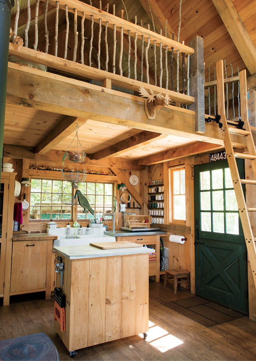
The library ladder is removable.
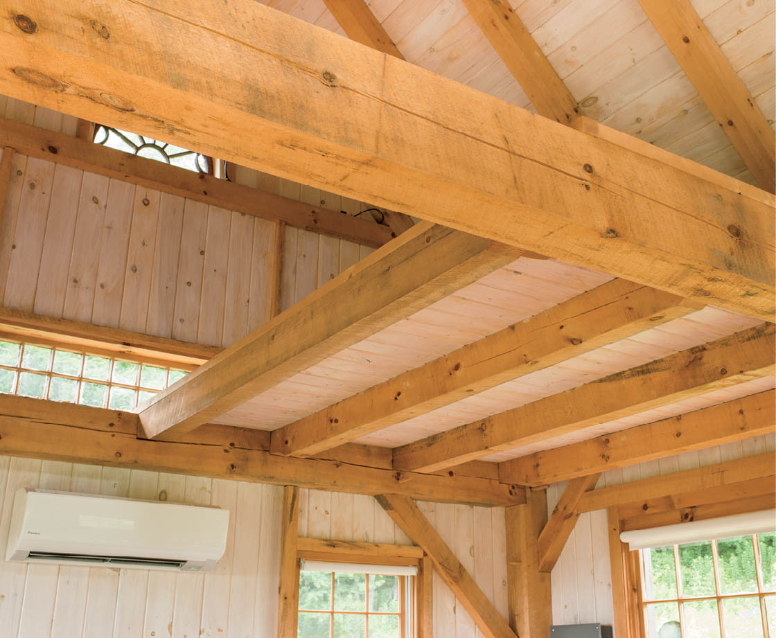
In the larger 16-foot by 20-foot version of the frame, the partial loft covers a quarter of the area (8 feet by 10 feet) and is used mostly for storage.

Even in the smaller 10-foot-wide version of the frame, the loft can still be an attractive and useable space.
The joists are arranged similarly to those in the main floor, with the center joist(s) (two if you have four joists, one if you have five) being a soffit tenon and the others drop-ins, with the pocket laid out 5 inches in from the outside layout face of the north tie beam, and 2 inches into the layout face of the center tie beam. In our core frame, if the loft is framed in the north bay, the shoulder-to-shoulder length of the soffit-tenoned joists is 7 feet 81⁄2 inches minus 61⁄2 inches plus 1⁄2 inch, or 7 feet 21⁄2 inches (just like the girts). Add 4-inch nominal (37/8 inches actual) tenons. The drop-in joists have an end-to-end length of 7 feet 81⁄2 inches minus 5 inches plus 2 inches, or 7 feet 51⁄2 inches; then subtract an extra 1⁄4 inch overall for clearance at the back of the pockets.
Reduce the joists down to 41⁄2 inches in height where they enter the tie beams, just like with the lower joists.
If you want more headroom in the loft, you have a few options. You could make the building wider (see Making the Frame Bigger) or increase the roof pitch; both changes make the rafters longer. You could also make the posts longer, but the distance from the top of the tie beam to top of the plate should not exceed 2 feet with 7×7 posts. If you want to go higher (up to 4 feet between the tops of the plate and beam), you should increase the post size to 8×8. This means most of your other timbers also need to be increased in size so that widths match. Going to 7×9 posts is another option, with the depth of the post increased to resist the greater force on the top of the post. As the post gets longer, the plate (which is carrying the outward thrust of the rafters) gets further away from the restraint of the tie beam. This means that the post has to be thicker to resist the bending imposed by the roof.

View looking down on loft joists (rafters and floor joists not shown)
The 12:12 roof pitch on our core frame is relatively easy to lay out and cut because all of the angles are 45 or 90 degrees. Once you change that pitch the peak and seat joints become a bit trickier.
You may want to lower the pitch for aesthetic reasons, such as to match an existing building on-site, but you’ll lose headroom in the loft (should you want one). As the roof gets flatter, the outward thrust on the plates also increases. To resist this horizontal bending on lower-pitched roofs, we turn the plate on its side so it becomes an 8×7 instead of a 7×8. Since the plate is now wider than the 7-inch posts, you can map the housings to match the tops of the posts, or just let the housing go all the way across and accept the visual consequences (it’s much easier to cut).
The bridle joint at the peak will have angles other than 90 degrees if the roof pitch changes from 12:12, and it would be useful to make a template for laying out the mortise and tenon. On the view below, note how we extended the reductions on both the mortised and tenoned rafters. This makes it easier to cut than an acute shoulder, and it looks better.
The step-lap rafter seat also changes as the roof pitch changes. As the roof gets shallower, the lines for the back of the joint on the top of the plate move inward, and the line on the face of the plate moves up; the opposite happens as the pitch gets steeper. You can calculate these shifts by using the Pythagorean theorem, or create a drawing with your framing square to help you see it, and take the measurements right off the drawing. The illustration below shows the adjusted measurements for a step-lap rafter seat for an 8:12 roof.

|

Use the following instructions to create a template for an 8:12 roof pitch. You can make templates for other pitches by holding the appropriate rise on the tongue of a framing square, and the run on the blade.


The rafter tails in our core project extend 16 inches past the plate to form the eaves, and the plates extend 12 inches beyond the gable ends to create an overhang. You may want more overhang, depending on how thick your enclosure system is and how much you want to protect it. For 2-inch-thick rafter tails, 18 inches is close to the limit; if you want more (up to 30 inches) you should increase the rafter tail thickness to 3 inches. This will result in the rafters sticking up 1 inch above the arris of the plate, but you can close that off with beveled strips between the rafters before you sheath the roof. It’s possible to extend the rafter tails out to 48 inches (maybe for firewood storage), but in this case you should support the overhang with a braced 2×4 “outrigger” and increase the tail thickness to 31⁄2 inches.
The plates could extend out to 24 inches without being increased in size, and even further if you add external braces. This would allow you to have a small porch or covered entry. If you are using the frame as an addition to an existing building you can eliminate the gable overhang on the end that joins the other structure.

The rafter plates can be extended on the exterior to form a porch or door overhang.
|

Making the frame smaller will not affect the sectional dimensions of pieces, since the joinery still requires a minimum amount of wood to be functional. Lengths will change, and if you reduce the building to less than 12 feet in length, you can eliminate the center bent. If the plate span increases to over 10 feet, however, you should increase the size of the plate to 7×9 and get a No. 1 grade timber.

The meditation cabin is 10 feet wide by 14 feet 6 inches long and includes a half-loft and covered entry.
|

This illustration shows a smaller frame (10×12) with a porch addition on the eaves side, bringing the entire structure back up to 12×16.
Increasing the three-bent frame up to 14 feet in width and 20 feet in length won’t increase the size of the timbers, except for main-floor joists, which should be increased to 5×8 or go up to No. 1 grade. When the building increases to 16 feet in width, add a central 10×8 girder to the floor frame and a central foundation pier. In this case, the joists would drop into pockets on both sides of the girder, so the extra width is required. Again, if the plate span increases to over 10 feet, you should increase it to a 7×9 and get a No. 1 grade timber. If the tie beams are going to carry a loft, increase their size to 7×9.

If the foundation is not continuous, piers should be placed under each post and in the center of cross sills as shown.


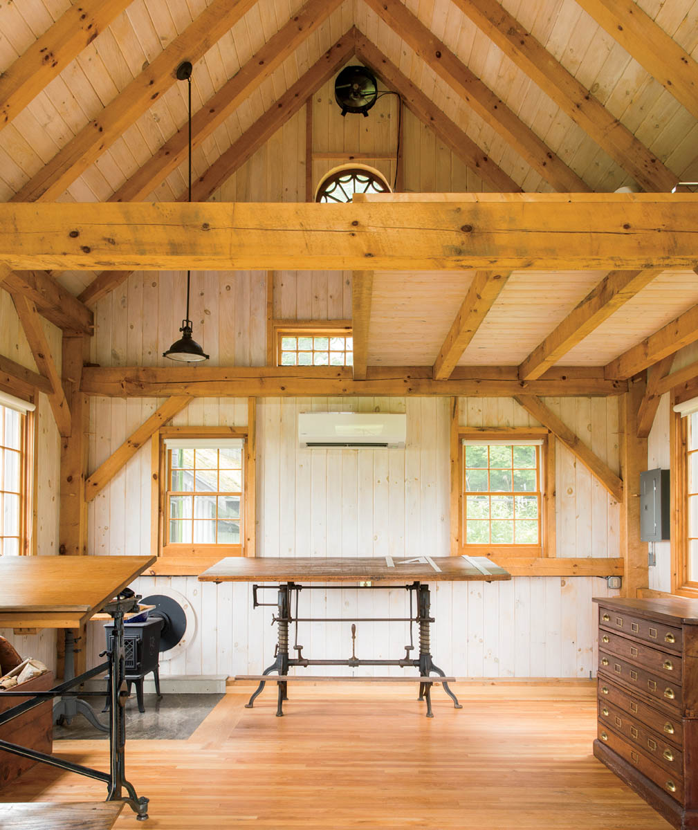
If these structural options are confusing, it’s a good idea to learn the basic engineering calculations for sizing beams, or get a spreadsheet that has the formulas built in. There are many combinations of size, grade, species, and spacing that can be found to work in any given situation. Your best option, of course, is to get your design reviewed by a qualified professional.
Instead of using 7×9 plates and tie beams, you could increase the posts — and the major timbers joining to them — to 8 inches in width. A No. 1 grade 8×8 plate can span up to 12 feet on a frame 16 feet wide (use an 8×10 timber if No. 2 grade). If you can’t get plate timbers long enough to span the entire building length (including overhangs), it’s possible to scarf the timbers together, making an end-to-end joint to make one long timber out of two shorter ones. This is more work, however, and not as strong as a single full-length timber.
The 5×5 rafters will work up to a 16-foot-wide roof span, given the design’s snow load and roof pitch.
One of the best ways to expand the basic 12×16 frame is simply to add modules to it. Multiple 8×12 sections can be added to the gable ends to make a building as long as you want, with scarf joints used to extend the plates and sills, if you can’t get timbers long enough.
Adding an extension to the eaves walls requires extending the roof rafters. If you maintain the same pitch as the main roof, the outer extension wall will have to be shorter to carry the rafters.
As you can see, a lower pitch, such as 8:12, makes it easier to extend the roof, rather than having to change the slope partway down. Alternatively, you can change the extension roof to a shallower pitch and/or make the main posts taller. Examples are shown.
Note that tie beams are required to connect the extended wall to the core frame, and these come in to the center posts slightly lower than the main ties. The lower ties connect to the outer plate on the addition at the same elevation to conserve height. Because the outer posts are coming into the same plate from below, this condition requires different joinery, as shown in the detail below.
The rafters are supported on both ends, so there is no thrust on the joint between the tie beam and plate. This contributes to the joint’s simplicity, since it doesn’t need to provide tying action. This lack of thrust on the rafter foot allows us to use a simpler birdsmouth joint, as shown, instead of a step lap.

Locate scarfs where bending and shear stresses are lowest; consult Historic American Timber Joinery (see Resources) for guidelines.

A 4-foot extension on the rear eaves wall of this frame is made possible by the lower-pitched roof.

This version uses an off-center middle bent to create a larger bay for the tractor. Note that the rear tie beam meets the post at a lower point than the main tie beam and therefore needs just a simple mortise-and-tenon joint. However, on the rear wall, they join the plate at the same height, and thus need the joinery.
|

Note: End grain of plate not shown so that joinery within is visible
In the frame shown on above, the extension tie beams come in low enough not to interfere with the wedged dovetail tying joint of the main ties. In this case, these outer ties can have a simple 4-inch tenon at each end. If the tie beams are close enough to interfere with each other, a spline joint can be used to connect them together and provide the tying action required.
A spline is a separate piece of hardwood or LVL (laminated veneer lumber) that is used to join beams coming into opposite sides of a post at the same (or nearly the same) elevation. Because there is not enough room within the post for sufficiently long tenons on the end of each beam, the spline passes through the post, extends into a long mortise in each beam, and then is pinned to each. Thus, one beam is directly attached to the other, with no pins needed in the post. This is especially helpful if the joint must have some tying capacity.
Splines should be long enough to extend at least 14 inches into each beam (16 inches is better), and are 11⁄2 inches thick (or 13⁄4 inches thick if you are using LVL) by 31⁄2 inches wide (51⁄2 inches for beams over 10 inches deep). Two pins are sufficient in each end of the spline, about 4 inches apart and slightly staggered so they aren’t in line along the grain. This is not an issue in an LVL, but in solid wood the fibers are arranged longitudinally, and the tension stress in the spline could cause the wood to split if concentrated along one shear plane. By staggering the pins the stress is distributed along multiple planes of fiber. The outer pins should be about 5 inches from the ends of the spline. If the beams are at slightly different heights, the spline can go into the top part of the lower beam and the bottom of the upper beam.
You don’t see many splines in older timber frames because the long mortises were difficult to make — and still are with hand tools. Today, power saws and chain mortisers make this difficult joint easier to execute, helping to solve this tricky problem of beams meeting at the same height on a post.
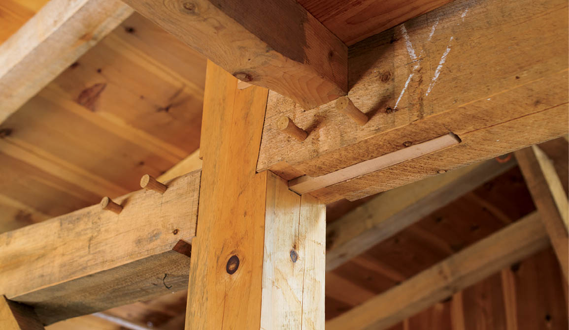
This “over-and-under” spline goes into the top of one beam and the bottom of the other. Splines are often used to connect beams coming into all four faces of a post at the same elevation.

An 8-foot-wide addition on the eaves wall will require a change in the roof pitch. Since the tie beams for the addition are close to the main tie beams in elevation, they require spline joinery.
|

This full 10-foot addition to the eaves wall requires an even lower-pitched roof (35⁄16:12), and the main roof is lowered to 10:12. In cold climates, the intersection of the two roofs should be sealed well with an ice and water shield.
In this variation, a 10-foot addition has been added to the left side and a 12-foot addition to the right.