Chapter 6. Installing ServoBlaster
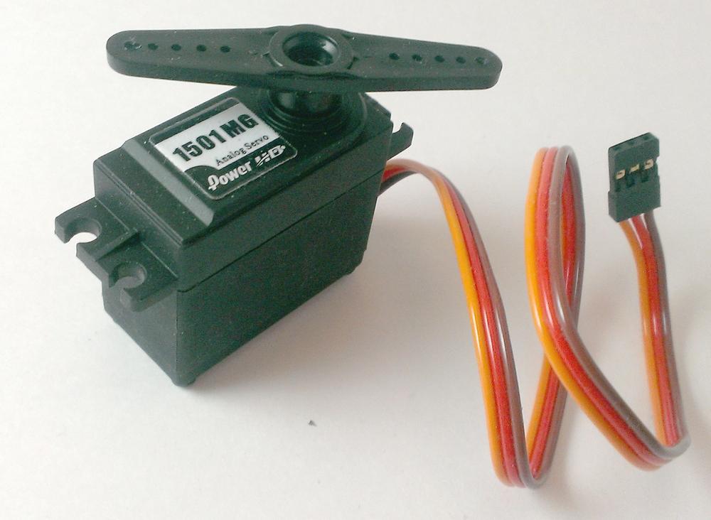
The current design of the rover has only one servo: a high-torque model used for raising and lowering the robotic arm (Figure 6-1).
However, you may decide to add more servos as the build progresses. You could change the design of the arm to give it two or three degrees of freedom (DOF), or you might add other attachments such as a gripper claw, a sample return arm, or a laser turret. Whether you keep the rover simple, with just a robotic arm, or you add to its capabilities, you’ll need to be able to control those servos smoothly and effortlessly.
Servos
At its core, a servo (or servomotor) is really nothing more than a DC motor, over which you have a certain amount of fine-grained control. How much control depends on the type and make of servo and the software or hardware you’re using to control its movement. Probably the most common place to find servos is in radio-controlled vehicles, but they’re also used in animatronics, robotics, and other types of automation. They are often mechanically linked to a small potentiometer, which sends positional feedback to the controlling software or hardware. In this way, the controller is always aware of the servo’s position, and can send or modify commands based on that position.
There are two types of servos: standard and continuous. The core of the servo remains the same; the only difference is what you can do with it. A standard servo can rotate between 0 and 180 degrees (a half turn) or only between 0 and 270 degrees (a three-quarters turn). When you send a servo a command to rotate to a specific position, that command is translated into a specific number of degrees for the servo to rotate. Depending on the servo, this can be as accurate as 1/3 of a degree. There are even some high-precision, high-quality servos that offer a turning resolution of 0.07 degree, though something that precise can cost upward of $500. Most hobbyist servos have a precision of a few degrees, which is plenty for most purposes.
A continuous servo, on the other hand, is more like a regular DC motor than a standard servo. A continuous servo can rotate 360 degrees; when you send it commands, those commands are translated to a rotational speed rather than a position. This means that you can’t tell a continuous servo to rotate 720 degrees (two complete rotations) and then stop. Rather, sending a value to it will make it turn continuously, either clockwise or counterclockwise, at a certain speed, depending on the value sent. Sending the value 75 to a standard servo may make it turn 90 degrees and then stop, for example. Sending the value 75 to a continuous servo, on the other hand, may make it start turning slowly counterclockwise. It will continue to turn at that speed until you either power it off or send it a stop value (often 0, but it may vary depending on the servo). Because of this behavior, continuous servos are often useful as drive motors.
PWM Control
You don’t need a special library to control the servos. As it turns out, the RPi.GPIO library we use to interact with the Pi’s GPIO pins is capable of the type of output necessary to control servos: pulse-width modulation, or PWM.
The RPi.GPIO library is included in all recent Raspbian distributions, though not in the early versions. To see whether you have it, fire up a Python prompt on your Pi with the command:
python
Then type the following command:
import RPi.GPIO
If you get an ImportError, you can easily install the module by exiting
your Python prompt with Ctrl-D and then type the following:
sudo apt-get install RPi.GPIO
If it still doesn’t work, you might have to completely delete your current RPi.GPIO and install a new one afresh:
sudo apt-get remove RPi.GPIO
sudo apt-get install RPi.GPIO
PWM is simply the process of sending precisely timed bursts of power to a receiver, such as an LED or a servo. To be understood and acted upon by the servo, the pulses must be at a particular frequency—most often 50Hz, or one pulse every 20ms. It is the width—or length—of the pulse that determines what the servo will do. An ON pulse that lasts 0.5ms, sent every 20ms, will send the servo all the way to the left, or counterclockwise. A pulse of 2.5ms, on the other hand, will send it all the way to the right, or clockwise. Different pulse widths between those two extremes will send the servo to any position you choose.
So how do you send these millisecond pulses to the Pi accurately? Like all processes running on the Pi at any given time, Python is constantly being interrupted (even if only for a millisecond or two) by system-level processes. This makes precise timing of a pulse impractical, if not impossible. Luckily, the RPi.GPIO library has what we need: the ability to set a particular pin as a PWM pin and give it a duty cycle necessary to power a servo.
When I say “duty cycle,” I’m referring to the length of time the signal is HIGH during each 20ms span of time. It’s probably best illustrated by the graph in Figure 6-2. A 0.5ms pulse can be translated to a duty cycle of 2.5%, a 1.5ms pulse translates to a duty cycle of 7.5%, and so on. The 20ms pulse is a given using the PWM pin, so the duty cycle easily translates to a pulse width.
To use PWM with the RPi.GPIO library, you need to connect the servo’s signal wire (usually the white or yellow one) to one of the Pi’s GPIO pins, and then use the GPIO.PWM() function. For example:
importRPi.GPIOasGPIOimporttimeGPIO.setmode(GPIO.BOARD)# This sets up GPIO pin 11 as our output pinGPIO.setup(11,GPIO.OUT)# This sets pin 11's frequency to 50Hzp=GPIO.PWM(11,50)# This sets the duty cycle to 7.5 (centered)p.start(7.5)# To sweep back and forth, we change duty cycleswhileTrue:p.ChangeDutyCycle(7.5)time.sleep(1)p.ChangeDutyCycle(7.5)time.sleep(1)p.ChangeDutyCycle(2.5)time.sleep(1)
Don’t forget to power your servo with a separate battery (like a 9V for testing purposes) and to tie the external power supply’s ground to your Pi’s ground (pin 6).
Running this script should make the servo sweep left and right, pausing for a second between each direction change. However, if you run it with a servo attached, you’ll notice that the servo movement is extremely jerky and noncontinuous. It’s because, despite our best efforts, PWM output on the Pi is not as easy to manage as it is on a simple microprocessor such as the Arduino. While functional, it’s not pretty. There’s got to be a better way to do it.
ServoBlaster
Enter ServoBlaster, a very helpful library written by Richard Hirst. It runs unnoticed in the background as a daemon, and allows you to smoothly control a servo either within a Python script or even directly from the command line. It’s also easy to download and install; you don’t even need to use Git (the download/version control tool) to get it.
To install, first navigate into the directory where you’re going to be putting all of your rover’s Python code. Then, in the terminal, type this:
wget https://raw.githubusercontent.com/richardghirst/PiBits/master/ServoBlaster/user/servod.c
followed by:
wget https://raw.githubusercontent.com/richardghirst/PiBits/master/ServoBlaster/user/Makefile
You now have the two files you need. To install ServoBlaster, simply type the following:
make servod
To start it (as I said, it runs in the background), type:
sudo ./servod
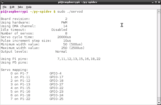
You should see a screen full of code detailing the program’s settings, including a servo mapping (Figure 6-3).
This mapping can be a little confusing, so it bears some explanation. First of all, you’ve probably noticed that the Pi’s GPIO numbers don’t correspond at all to its physical pin numbers (physical pin 4 is GPIO pin 2, for instance). When you use the RPi.GPIO library, therefore, you must specify whether you’ll be referring to pins in your program by their physical pin numbers (with GPIO.setmode(GPIO.BOARD)) or by their GPIO numbers (with GPIO.setmode(GPIO.BCM)). The ServoBlaster library, unfortunately, adds another layer of complexity to this pin-mapping mess. The introductory splash screen tries to illustrate it, but with limited success. Referring back to Figure 6-3, you’ll see that the eight
servo pins that ServoBlaster uses are mapped to eight specific physical pins on the Pi: 7, 11, 12, 13, 15, 16, 18, and 22. Those physical pins, in turn, correspond to GPIO pins 4, 17, 18, 27, 22, 23, 24, and 25, respectively. ServoBlaster refers to those pins (servos) as servos 0, 1, 2, 3, 4, 5, 6, and 7, respectively. So if you want to control servo 0, you’ll connect the servo’s signal wire to the Pi’s pin 7, also known as GPIO pin 4. If you want to control servo 5, you’ll connect the servo to the Pi’s pin 16, also called GPIO pin 23. And so on. Clear as mud? Don’t worry, it will make more sense as you get familiar with the library. In the interest of keeping things simple, I use GPIO.BOARD mappings in this book, which has the added benefit of ensuring that the code here will run on whatever version of the Pi you happen to be using. If you’re not using GPIO.BCM mappings, you can safely ignore the GPIO pin numbers I refer to.
To test the library after you’ve installed it, connect a servo to your Pi’s GPIO pin 18 (pin 12). Keep it powered with your 9V battery, and in your terminal, type:
echo 2=150 > /dev/servoblaster
Your servo should immediately do something interesting. The command follows the syntax echo (servo=value) > /dev/servoblaster. You’re basically writing (echo) a value (servo=value) into the /dev/servoblaster file. The library maps a servo number to a pin; if you want to refer to servo 0 in your code, it’ll be the one plugged into pin 7 (GPIO pin 4) on the Pi. In order to use this syntax in our Python code, we’ll simply use the subprocess library:
import subprocess
subprocess.call("echo 2=150 > /dev/servoblaster", shell=True)
You’ll want to play around a bit with values you send to the servo, perhaps by writing a simple interactive Python script—an exercise I leave to you. Different servos respond differently; I’ve noticed discrepancies even between two servos of the same model and manufacture. Be aware, also, that only certain GPIO pins will work with the library. That is, the ServoBlaster library can control up to eight servos at a time, but only on the eight particular pins I mentioned previously. You’ll need to investigate what values to send to the servo to make it move the way you need it to: depending on how you install your robotic arm, you’ll need to know how far up to lift it and what value it takes to get it there.
Many thanks to Richard Hirst for his code library, written and freely given to the Pi community for projects like ours. If you need more information regarding the library and how to use it, check out his README file.


