Chapter 7. Bot Construction
Now that we’ve gone over the history of Linux, and what the Pi is and what it can do, and how to set up the wireless, and (of course) the parts required, it’s time to get down to some robot building. Remember, Rome was not built in a day, and neither will your rover. Take your time with the build, and plan out what you do before you do it. You know the saying: measure twice, cut once.
This is especially applicable if you are using the rover in this book as a suggestion, and not a step-by-step instruction list. With each modification you make (and you are encouraged to make them), you’ll be faced with design decisions not mentioned here. I hope to prevent you from making some avoidable mistakes, but obviously I can’t anticipate every possible design.
The Body
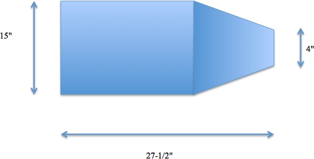
The most obvious place to start the build is with the body. Starting with the 4’ × 4’ piece of plywood, cut a piece large enough to become the base of the rover. Sketch it out or plan it on paper before you decide on size; it’s going to have to fit two motors, at least two batteries (one for the Pi and at least one for the motors), a motor controller, at least one breadboard, the Pi itself, and several sensors. I made mine vaguely coffin-shaped, about 28” × 15” (Figure 7-1).
The shape is immaterial; if you want to go with a rectangular base to keep it simple, that’s a great idea too. I was just feeling particularly motivated when I laid out the coffin design.
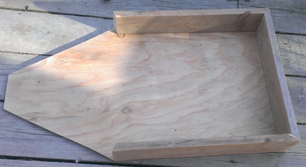
After you’ve designed and cut the base shape from the plywood, you’ll next need to measure and cut the 1 × 4s to go around the edges. These are going to serve as the sides of the body. After you’ve cut them to fit, attach them to the base with screws or wood glue (Figure 7-2).
If you’re going to attempt to make the body smooth (for aesthetics), it might behoove you to experiment with dovetails and 45-degree corner cuts to make the sides fit the base as snugly as possible. On the other hand, if you’re not a carpenter, or are going for the “backwoods home-brewed robot” look, don’t worry too much about how the sides fit. For that matter, you could conceivably build most of the rover on a flat base with no sides—just some upright portions through which to slide the axles.
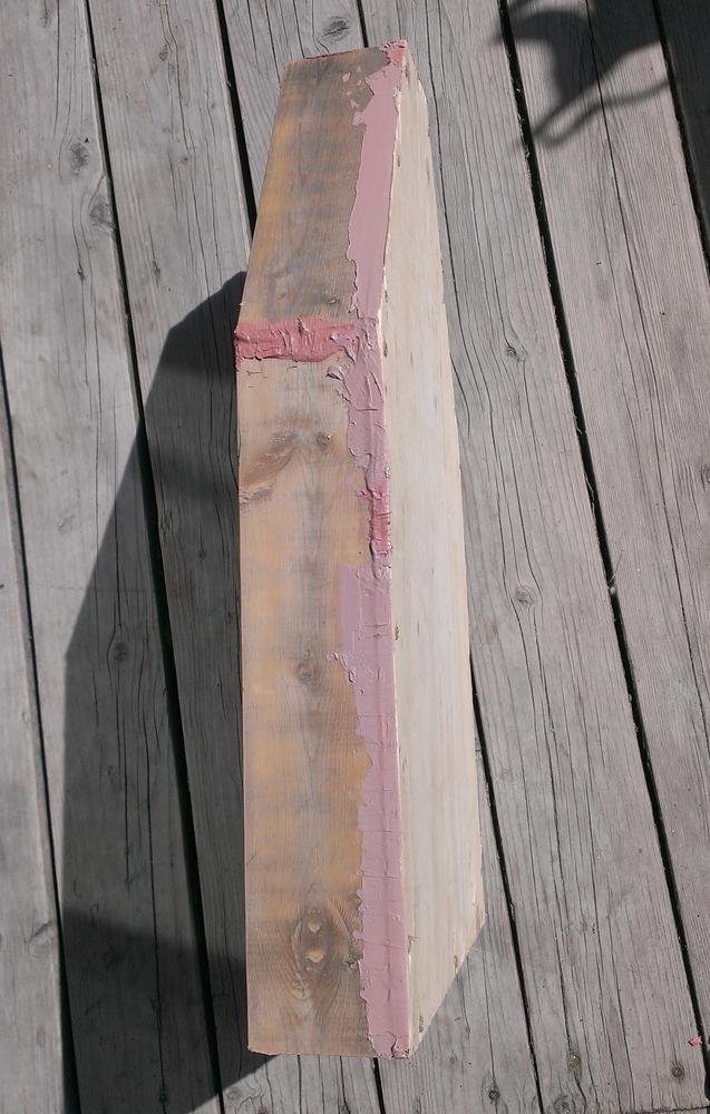
When the sides are firmly attached, sand them as smooth as you can. If you have a lot of gaps and cracks, and if you’re going for the smooth look, get some fiberglass paste (sold at auto parts stores for filling dents in auto bodies), and apply it to the cracks (Figure 7-3). Follow the instructions on the package to apply it, and after it sets and dries, sand it as smooth as you can. I normally do this sanding by hand, rather than with an electric sander, because it’s much too easy to press too hard with an electric sander and remove more material than you planned. If you get a sanding block, not only will your surfaces be flat, but the block will help save your hands from fatigue. Start with a pretty rough grade to shave down the lumps, and then use finer and finer grade to get the surface smooth.
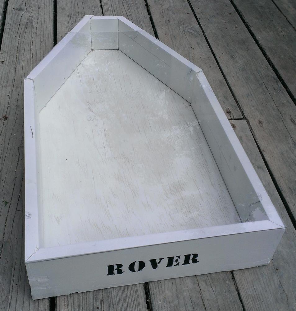
Once it’s as smooth as you can get it, quickly go over it with a damp sponge or cloth to wipe up the dust, as the dust will prevent paint from sticking properly to the surface. Finish up by painting the body with a primer and a final coat of paint. Feel free to decorate as you see fit (Figure 7-4).
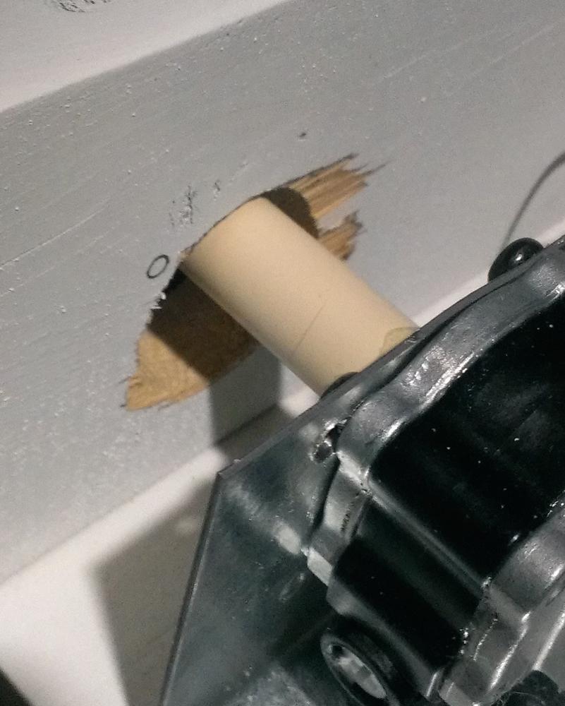
The next step in the construction of the body is drilling holes to hold your wheel axles. With the body and motor design I outline here, you’ll want to keep the holes for the front axle as close to the actual size of the axle as possible to make it a tight fit. The rear axle holes, meanwhile, should be a bit larger to allow the axles to move as the rover moves (Figure 7-5)—sort of like shock absorbers. The rear axles will end up being made out of short pieces of flexible PVC pipe, so giving them some room to bend will allow the wheels to have more “give” when traveling over uneven ground. The axles will be rubbing against the wood, but the rover won’t be going fast enough for the friction generated to affect its travel. If you prefer, however, you can find bearings that fit the axles and use them in the rear holes as well as on the front axle.
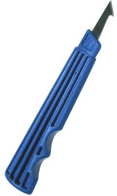
Finally, if you plan to use a plexiglass cover for your rover, now is a good time to attach it. Using a plexiglass cutter (Figure 7-6) and a straight edge, cut it to fit the shape of the rover’s body. You’ll need to cut a bit out later to accommodate the robotic arm, but make sure it fits the body shape.
Don’t attach the plexiglass to the body yet; it’s much easier to cut while it’s still unattached.
The Motors
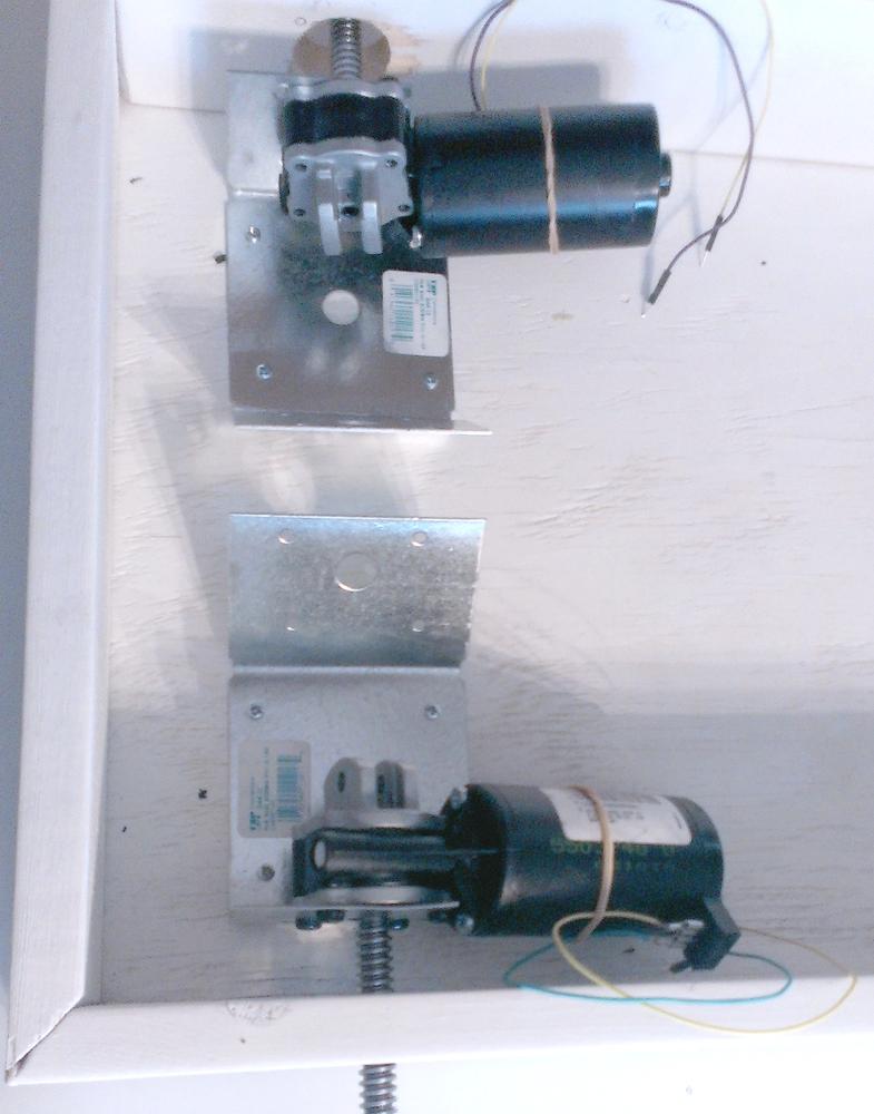
The motors can now be prepared and then mounted to your robot’s body by using brackets. The bracket must be thin enough to be attached with the motor’s original screws, yet strong enough to hold the motor’s weight. Spend some time shopping at the hardware store until you find a suitable bracket; I found these in the lumber section, as they’re used to connect 2 x 4s when framing a house.
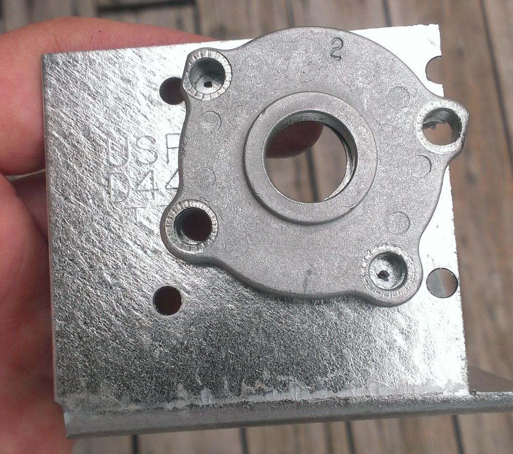
First, unscrew the faceplate from the motor and trace the hole positions onto the mounting bracket (Figure 7-7).
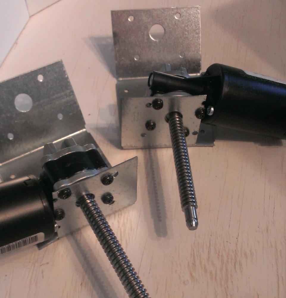
Now drill out the holes you traced onto the bracket. Make sure they’re large enough to slip the faceplate screws through, and then remount the faceplate to the motor with the bracket attached. When you’re finished, the faceplate screws should be not only holding the motor together, but also keeping the bracket tightly attached to the motor. This part of the project should end up looking something like Figure 7-8.
The idea here is to securely fasten the motors to your rover’s body, and the exact technique you use will depend on the motors and brackets you’re using. If you’re able to replace the faceplate screws with longer ones, you may be able to simply mount the motors to the side of the rover itself, eliminating the need for brackets. However, the motors I used have unique, tapered screws that can’t be simply replaced with longer ones, so I had to find a thin, sturdy bracket option.
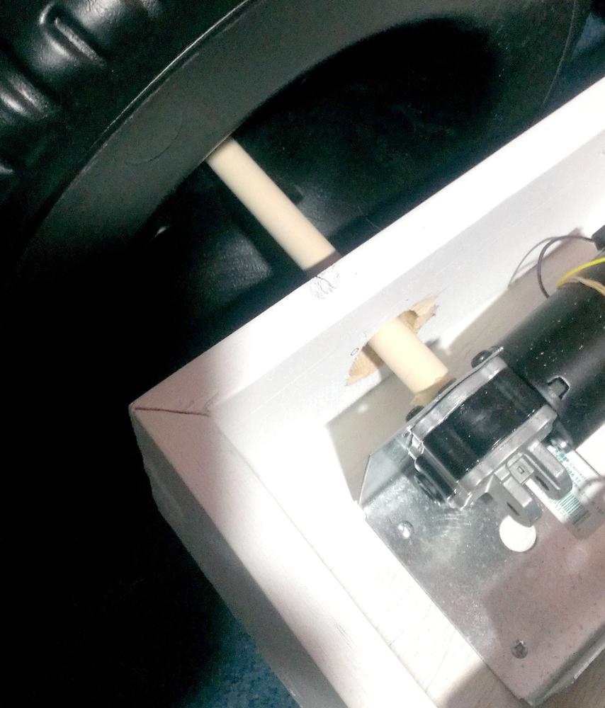
Finally, attach the brackets (with motor attached) to the rover base, so that the motor shafts extend through the holes in the side (Figure 7-9). Don’t worry if they don’t extend very far; we’ll extend them a bit when we attach the wheels.
The Wheels
Again, depending on the drive design you choose, this portion of the build may differ significantly from mine. However, if you’re also going for the direct-drive approach, you should go for something similar to this. Each of the two rear wheels is attached to a motor, which is controlled via software running on the Pi. Meanwhile, the two front wheels are attached to the front axle with bearings, meaning each wheel turns independently of the axle. This means that in order to turn the rover, you need to turn only one rear wheel or the other (or both in opposing directions), and the front wheel on each side will follow suit. It also means that the front axle must not turn with the wheels, or the rover will simply move forward, rather than turning. Keep the front axle snug in its hole, don’t be afraid to affix it permanently with glue or epoxy, and make sure the front wheels turn without problems.
Another possible wheel design (which I experimented with in theory as well) is a chain or belt drive. In this configuration, you need only one drive motor, which is then attached to the axle. A chain drive requires a sprocket or gear attached to the axle, while a belt drive will require some method of keeping the belt centered on the axle without slipping.
In my opinion, there are two disadvantages to the chain- or belt-drive model. First, keeping the belt or chain attached to the rear axle is a challenge; a sprocket for a chain would need to be solidly attached to the axle, and a belt would tend to slip on the axle unless you could devise a way of keeping it from doing so.
The second disadvantage is that if the rear wheels turn together, as they do in this configuration, then you must be able to steer the front wheels, either by twisting the entire axle or by turning the wheels themselves, the way the wheels turn on a full-sized automobile. Both of these present significant design challenges that you may or may not want to attack.
I prefer the direct-drive design, for the main reason that it lends itself well to being converted to a track design, like a tank. Connecting a track between the front and rear wheel on each side would make the rover even easier to steer and perhaps make it more of an all-terrain vehicle.
The Rear Wheels
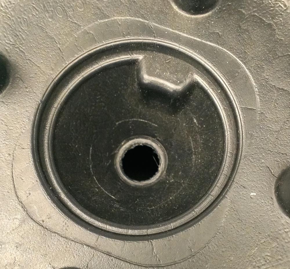
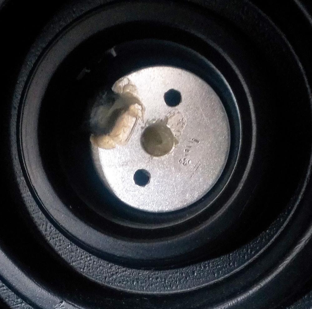
Each rear wheel is solidly attached to a length of small plastic pipe, with a diameter just large enough to slip over the motor’s shaft. To accomplish that, a strong epoxy, designed to attach plastic to plastic and plastic to metal, comes in handy. First, if necessary, use a round file to enlarge the hole in the middle of the wheel just enough to accommodate the pipe (Figure 7-10).
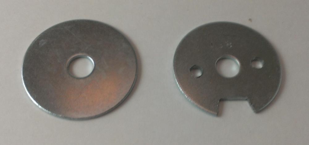
Before you epoxy the axle, you’ll want to create a sort of hubcap to help solidly attach the wheel. To do this, use a large fender washer with a notch cut to fit the wheel hub (Figure 7-11). The inner hole of the washer does not need to fit the plastic pipe, as you’ll be gluing it to the end of that pipe.
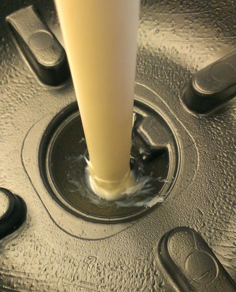
To connect the wheel, slide the pipe through the hole in the middle and use epoxy to attach it (Figure 7-12).
When the epoxy has set according to the instructions, flip the wheel over and glue the hubcap to both the wheel hub and the end of the axle (Figure 7-13). The notch not only gives more surface area for attachment, but also ensures that the wheel will turn when the axle shaft does.
The last step in the process of building the drive mechanism is to attach the axle to the motor shaft. There are two ways of doing this: chemically, with epoxy, or mechanically, with a cotter pin. I chose to use epoxy; if you’d rather use a cotter pin, make sure you have a sharp drill bit, as the motor shaft is likely to be hardened steel. Slip the pipe over the motor shaft and drill a hole through both. Then slide a cotter pin through the hole and bend the ends back. This method has the advantage that you can remove the axle shafts at any time.
If, on the other hand, you prefer to go the more permanent route, break out your trusty tube of epoxy again. Mix up a large batch and slather it generously over the motor shaft. When it’s fully coated, slide the pipe over the shaft and let the glue set according to the instructions. When you finish, you should have something like you see in Figure 7-14.
However you go about it, the end result should be an axle/wheel combination that turns when the motor shaft turns.
The Front Wheels
Luckily, the front wheel assembly is much easier, though again it uses epoxy. In order for the steering design to work, each front wheel must be able to turn without affecting the other front wheel. To accomplish this, they must be attached to the front axle with a bearing, and the axle itself must be firmly attached to the body of the rover. If you like, a viable alternative would be to use casters for the front wheels, as they don’t require an axle and can turn independently of each other. If you decide to go with that approach, make sure you can mount them solidly to your rover’s body and make sure that any off-road driving you intend to do won’t gum up the bearings in the casters. I prefer to stay with four matching wheels, which requires freely rotating wheels on an immobile front axle.
Once again, mix up a batch of epoxy and, working quickly, slather it over the inside of the front wheel where the axle would sit. Before the glue sets, affix the metal bearing to the wheel; the end result should be a bearing that is firmly attached to the wheel and can be slipped onto the front axle. It is also possible to simply make sure the wheel turns on the axle freely and keep it in place with a few strategically placed cotter pins, but the disadvantage is that the wheel may wobble quite a bit, contributing to the rover’s instability. Attaching the wheel to a bearing, which is then attached to the axle, ensures the wheels will roll smoothly and without wobbling.
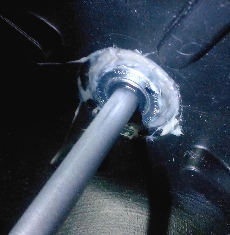
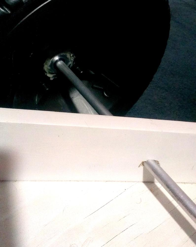
When the epoxy holding the bearing to the wheel is firmly set, slide the axle through the holes you drilled for it in the body of the rover, and then slide the bearing over the axle and attach it firmly (Figure 7-15).
I used cold-weld for this; it’s similar to epoxy, but specifically made for bonding metal to metal (aluminum to steel, in our case—the axle to the bearing). The final product should look something like Figure 7-16.
The Robotic Arm
Perhaps the neatest thing about this rover is the robotic arm. You can mount a webcam or the Raspberry Pi camera board to the end of the arm, and either take still pictures with it, or perhaps even navigate using a live stream. The high-torque servo allows you to raise and lower the camera, giving you the ability to get a good look around your surroundings.
Start by determining where you’re going to mount the arm on your rover’s body. For stability’s sake, you’ll probably want to mount it toward the center or rear of the rover, on the midline. Then decide how long you want the arm, and cut the aluminum channel to that length. Remember that the longer the arm, the more torque will be required to raise it, as the servo will be mounted at the hinge point on the rover’s body. The camera on the end will also contribute to the weight, as will the enclosure you design to hold it.
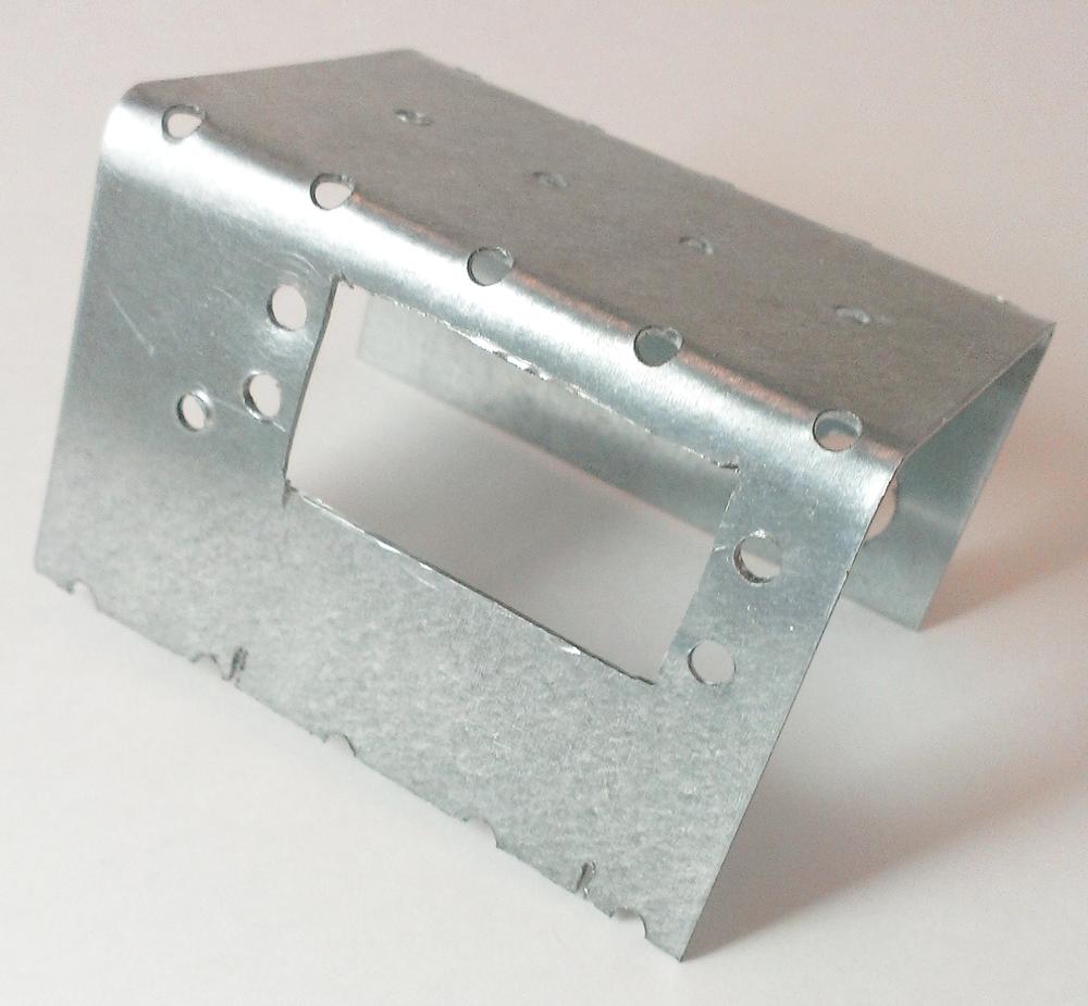
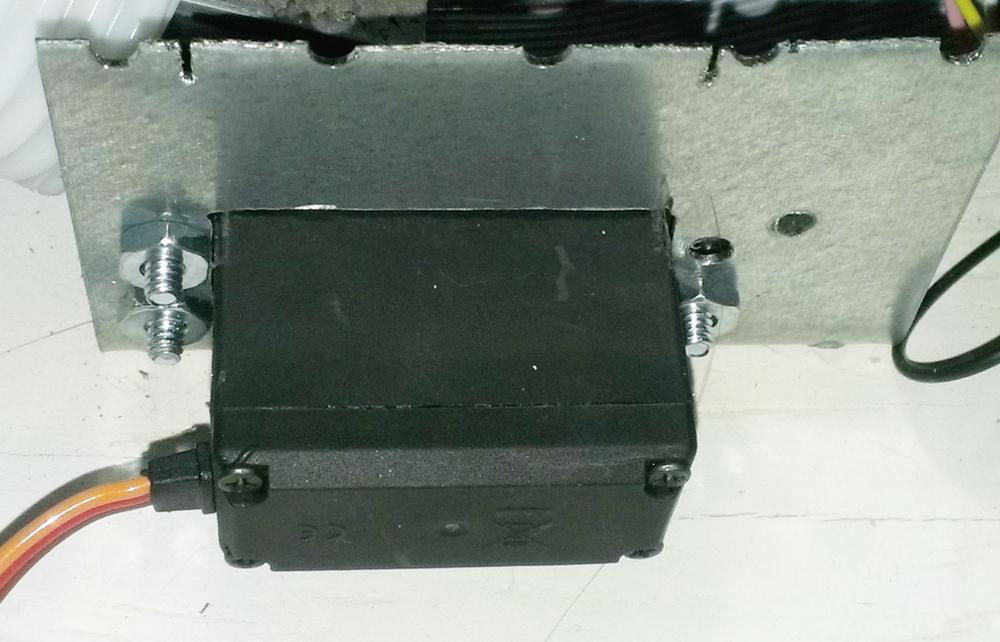
The high-torque servo will now need to be attached to a mounting bracket of some sort. I used a bracket similar to those I used to mount the rear motors. Cut a hole in the bracket that fits the servo snugly, and then slide the servo through and attach it to the bracket using the built-in mounting holes (Figures 7-17 and 7-18).
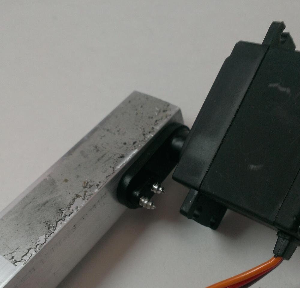
When the servo is firmly attached to the bracket, attach the length of aluminum channel to the servo’s horn by using some sheet-metal screws (Figure 7-19).
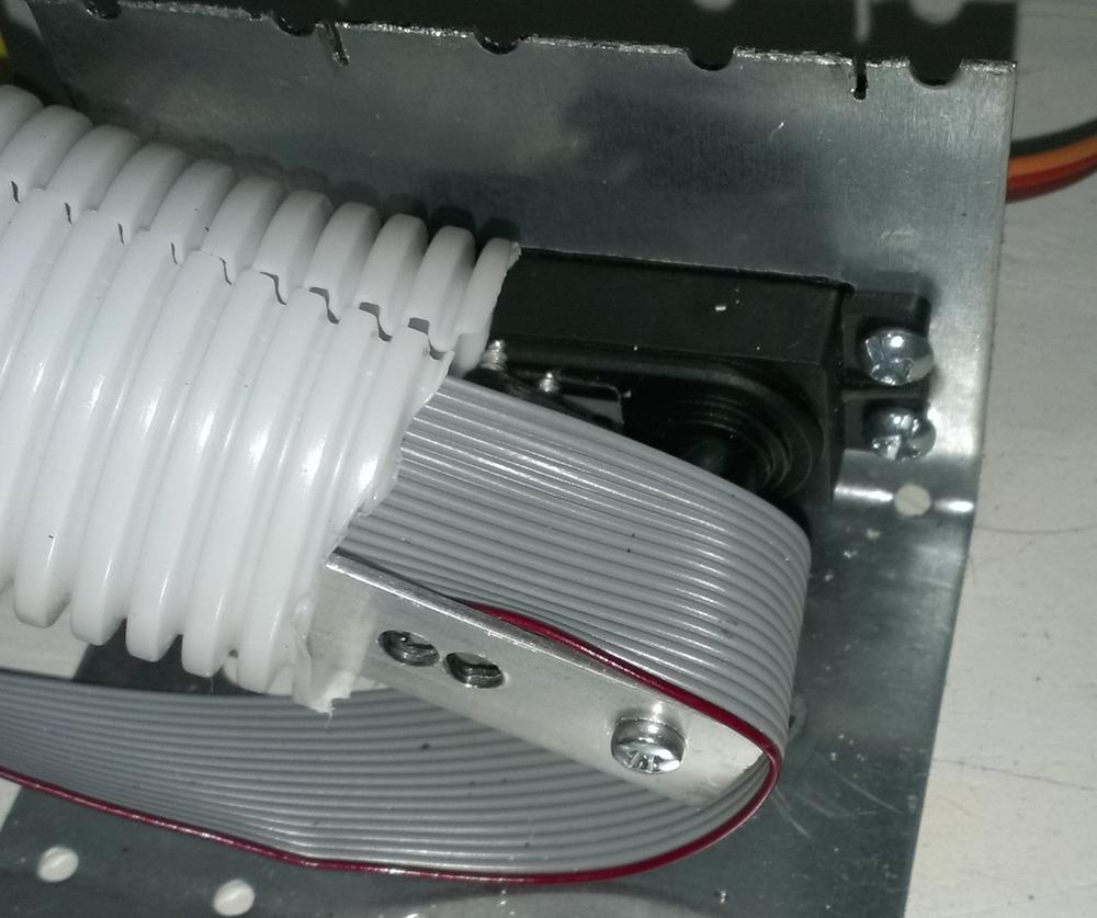
The whole assembly can then be mounted to the body of the rover (Figure 7-20).
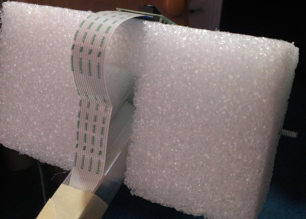
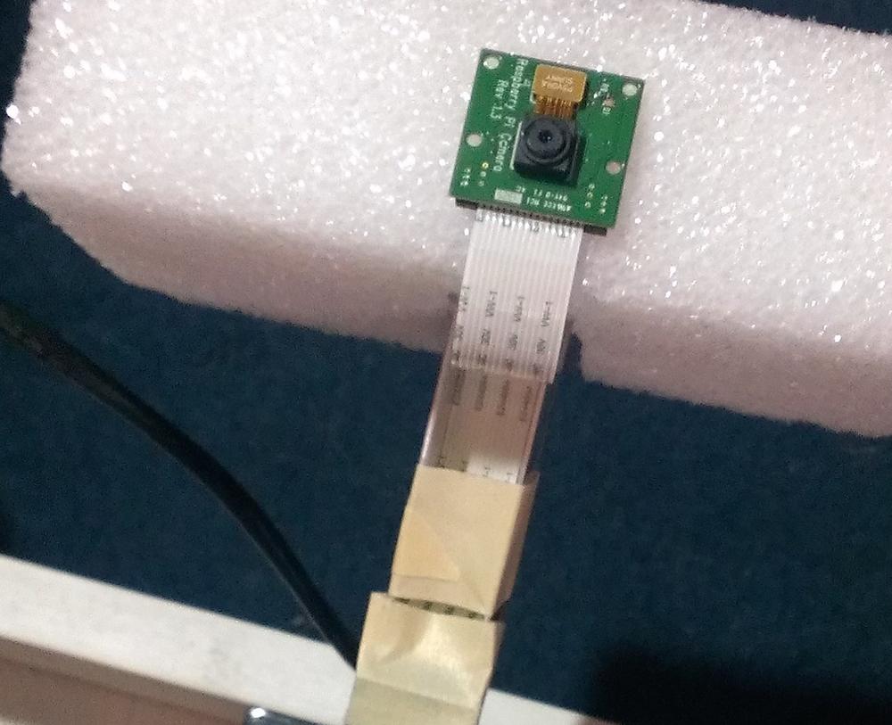
After your servo is attached, you can concentrate on the other end of the arm, where the camera(s) are attached. You’ll probably want some sort of enclosure, or at the very least a holder. To keep the weight down, I made the camera holder out of a block of craft Styrofoam. If you want to ensure that the camera is looking forward whether the arm is standing straight or laying forward on the body of the rover, attach the block of Styrofoam to the end of the arm, using a long threaded rod as a pivot. Carve out a section of foam for the end of the arm, and then mount the camera on the foam by using a bit of hot glue (Figure 7-21).
It doesn’t take much glue to attach the Pi camera, because it weighs so little, and the glue won’t damage the camera as long as you don’t use too much. To ensure that the camera remains level, you may need to add some weight to the bottom of the enclosure. Lead fishing weights or even a few large screws work well for this.
When you’re satisfied with the attachment and pivot, run your camera’s cable down the inside of the aluminum channel (Figure 7-22), using some tape to hold it in place.
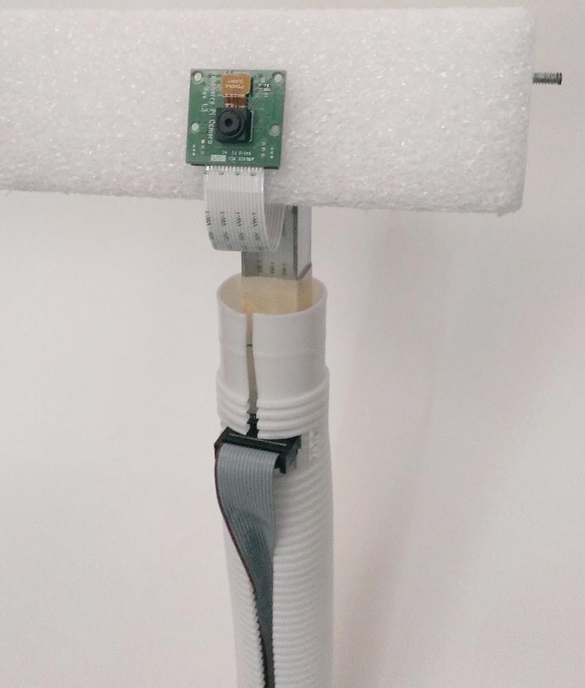
Finally, to hide the guts of the arm and its enclosed wiring, use a length of flexible plumbing hose, cut lengthwise to slide over the arm, with appropriately placed slits to accommodate the cable connectors where necessary (Figure 7-23).
Pi Power
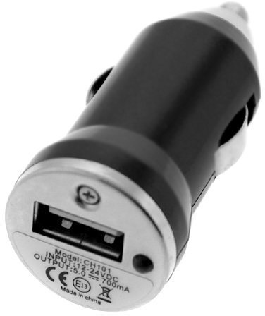
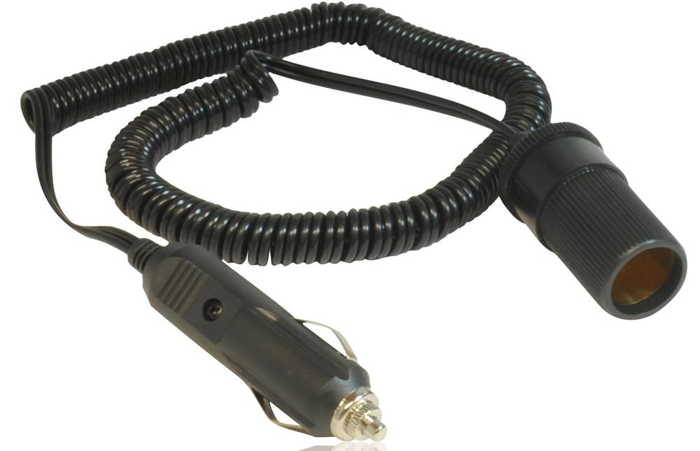
In order to supply your Pi with its required 5V with a Li-Poly battery pack, you’ll need to create some sort of connection between the battery pack and the mini USB cable used to plug into the Pi. You’ll also need to incorporate a voltage regulator of some kind to bring the battery voltage down to a Pi-friendly level. In my experience, the easiest way to accomplish all of these things in a small package is to use one of the USB chargers that plug into a car’s 12V socket (Figure 7-24).
The charger can be connected to the Pi with a short USB-to-USB mini cable. I use an extendable one. To attach the charger to your batteries, get an extension socket for the charger (Figure 7-25).
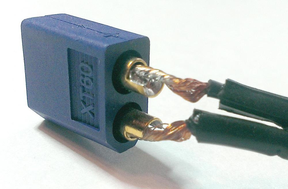
Cut off the end of the extension cord, and solder an XT60 female connector (or whatever type of connector matches your Li-Poly pack) to the end (Figure 7-26).
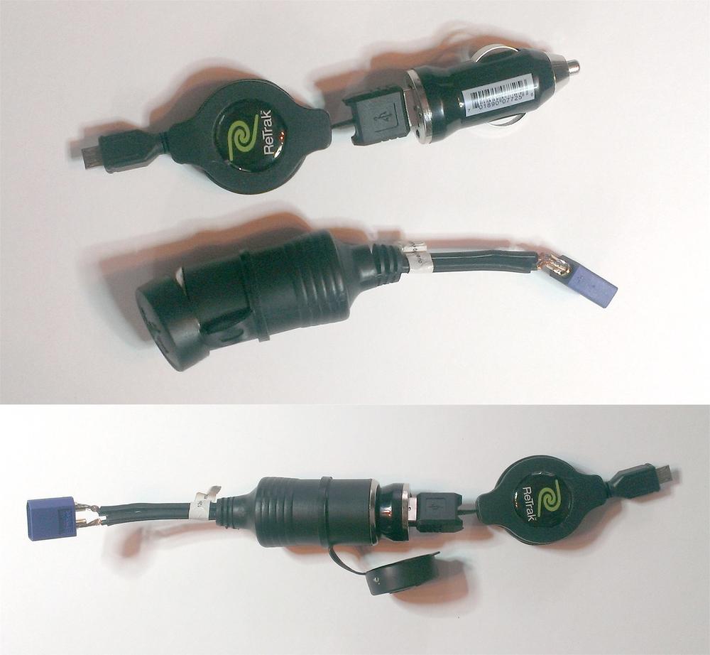
When you’re finished, you should have two self-contained power plugs that fit nicely together (Figure 7-27).
This allows you to plug and unplug battery packs as you need/go through them, and the voltage regulator keeps your Pi safe. All in all, it’s a portable power solution that I’ve used in many projects.
Placing Everything
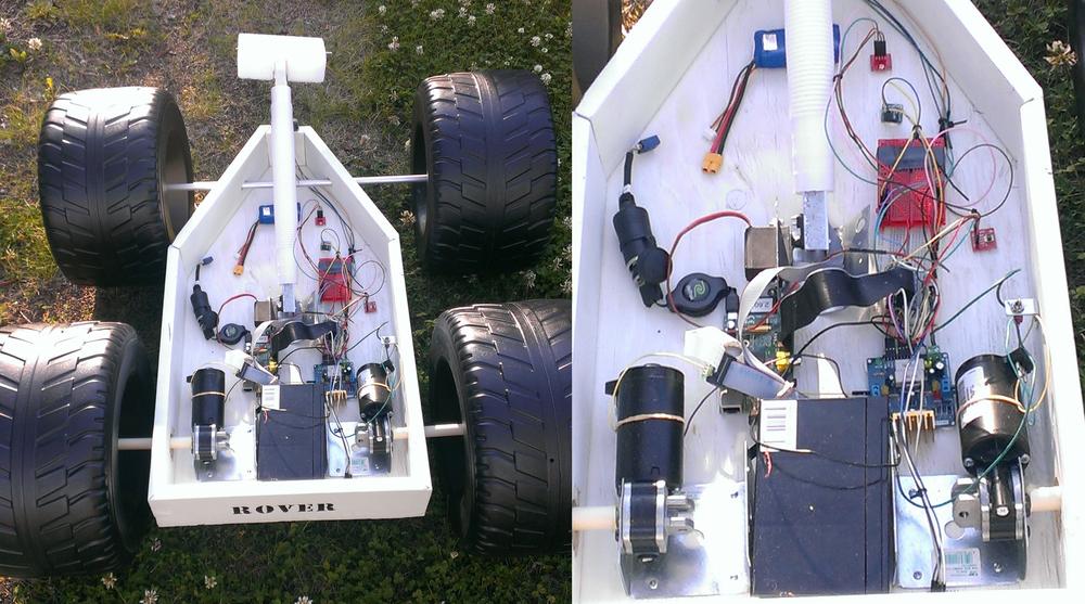
The last part of the construction of the rover is placing all of the parts inside, including the Pi, the L298H motor-controller board, the various sensors, and the batteries and breadboards used to power and connect everything. Obviously, this will depend heavily on your rover’s design, plus where you decided to place everything. Try to keep the wiring neat and tidy, and color-code wires where possible—use red wires for positive signals, black for negative, white for signal wires, and so on. Zip ties can be handy when it comes to bundling wires and cables. Your rover should end up looking something like Figure 7-28.
Finally, consider adding a switch between the power for the motors and the L298H board. By using a simple toggle switch to disconnect the power when the rover isn’t in use, you can prevent your large drive batteries from gradually leaking into the L298H board, prolonging their life. The Li-Poly packs used to power the Pi are easy to remove and recharge, but recharging the batteries I chose for the drive motors is a bit more involved; I use a car battery charger, and the less often I have to do it, the better.
Now that your rover is built, let’s look at adding some sensors to it.
