Chapter 9. Bot Location
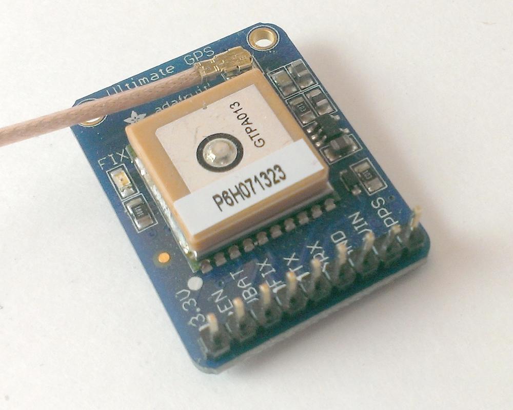
Once you’ve built a robot—particularly a mobile one, with wheels and perhaps a measure of autonomy—an important part of controlling it is knowing where it’s gotten to while you weren’t looking (see R2-D2’s escape in Star Wars Episode IV: A New Hope for a classic example). While I don’t think you’ll need to install a restraining bolt on your rover, knowing where it is and where it’s going, even to the extent of logging those locations to examine the route later in Google Maps or Google Earth, is definitely an exciting possibility. We’ll be using a GPS unit, shown in Figure 9-1.
GPS stands for Global Positioning System, a satellite-based navigation system that can provide the location and time (in UTC format) for any place on Earth where there is a direct line of sight to four or more GPS satellites. It was developed in 1973 and started with 24 satellites; the system has since been expanded to 32 satellites, all owned and operated by the U.S. government. If a GPS receiver on the ground can lock onto a signal from these satellites, it can pinpoint a location on Earth with an accuracy approaching 1 meter, and a timing accuracy of around 100 nanoseconds (more than precise enough to determine whether your rover is safely across the street). It’s often used in robotic systems, including military drones and Google’s unmanned cars. GPS was originally established for the U.S. military, but in 2000 President Clinton directed the Pentagon to make the signals freely available and unencrypted. They now can be accessed by relatively inexpensive devices, which, in our case, can then be connected to the Raspberry Pi.
A GPS unit might be a little more expensive compared to some of the other sensors on the rover, but it’s small, portable, and doesn’t draw much power. It’s also easy to set up and use. It can be purchased with an optional 5m antenna, but my experience is that the antenna isn’t necessary; I can pick up enough satellites to get a GPS fix inside my house without it.
Fun fact: the GPS system must take into account Einstein’s general theory of relativity during normal operations. Because ground-based observers are deeper within the Earth’s gravity well than the satellites are, the clocks onboard the satellites appear to gain 38 microseconds per day. This discrepancy means that the satellite would misrepresent your position by about 10 kilometers! Because such a drift would make GPS useless in only a few minutes, this gain is corrected for in the system’s design.
Preliminary Setup
In order for the Pi to communicate with the GPS receiver, you’ll first need to install the necessary Python library and its dependencies, and enable the correct interface on the Pi. The library is called gpsd, and it is available in the standard Raspbian repository. First, to install what you need, enter the following commands, one at a time, into your terminal, and let the package manager do its thing:
sudo apt-get update
sudo apt-get upgrade
sudo apt-get install gpsd
sudo apt-get install gpsd-clients
sudo apt-get install python-gps
(You may already have one or more of these installed, depending on your distribution version.) The Python gpsd module is part of a much larger library of code designed to allow devices such as the Pi and other microcontrollers to monitor and communicate with attached GPS and Automatic Identification System (AIS) receivers. It has been ported into C, C++, Java, and Python, and allows you to “read” the National Marine Electronics Association (NMEA)–formatted data transmitted by most GPS receivers. That means that if you decide to use a different GPS unit, either now or later, as long as that unit transmits the NMEA-formatted sentences, the Pi should still be able to understand the
data. I have even had some success with a few off-the-shelf units that
connect to the Pi via USB; you simply need to point the gpsd daemon to
the USB connection (a bit further on in this chapter) rather than the
UART one.
When you have the necessary packages and libraries installed, you’ll need to configure the Pi’s UART interface. UART stands for universal asynchronous receiver/transmitter. In simple terms, it is a piece of computer hardware that communicates information over a serial port, using the old reliable RS-232 serial protocol. The Pi has such an interface built in, preset to use pins 8 and 10 (GPIO 14 and GPIO 15).
By default, the Pi’s UART interface is set up to connect to and communicate over a terminal window, but that configuration does us no good for reading the GPS, so we need to reconfigure it. To do that, start by making a copy of the /boot/cmdline.txt file for safekeeping:
sudo cp /boot/cmdline.txt /boot/cmdlinecopy.txt
The cmdline.txt file is used to pass arguments to the Linux kernel. When you’ve saved a copy, edit the original:
sudo nano /boot/cmdline.txt
Its format is simply a space-delineated list of arguments. We need to delete the arguments that deal with terminal communications. In its original form, the file reads
dwc_otg.lpm_enable=0 console=ttyAMA0,115200
kgdboc=ttyAMA0,115200 console=tty1
root=/dev/mmcblk0p6 rootfstype=ext4
elevator=deadline rootwait
Delete this portion:
console=ttyAMA0,115200 kgdboc=ttyAMA0,115200
The file should now read (all on one line, obviously):
dwc_otg.lpm_enable=0 console=tty
root=/dev/mmcblk0p6 rootfstype=ext4
elevator=deadline rootwait
Save it, and then open the Pi’s inittab file with the following:
sudo nano /etc/inittab
The inittab file describes what processes are started at bootup and during normal operation. All we need to do here is comment out the last line, which tells the Pi to start a terminal connection. The unedited line looks like this:
T0:23:respawn:/sbin/getty
-L ttyAMA0 115200 vt100
Add a hashtag to the beginning so the line looks like this:
#T0:23:respawn:/sbin/getty
-L ttyAMA0 115200 vt100
Save the file. Now, reboot the Pi with:
sudo shutdown -r now
Communicating with the GPS Module
When the Pi is back up and running, it’s time to connect the GPS module and see what we can see. Though there are a lot of pins on the GPS unit’s header board, we’re using only four of them: VIN, GND, Tx, and Rx. Connect the VIN to the Pi’s 5.5V, the GND pin to the Pi’s GND, Tx to the Pi’s Rx pin (pin 10), and Rx to the Pi’s Tx pin (pin 8). It’s easy to remember the direction of the last two connections: just remember that the Pi must transmit (Tx) to the board’s receive pin (Rx), and it must receive (Rx) from the board’s transmit (Tx).
When the red LED on the GPS board starts to blink, you’ll know you have power. Now you can test it by starting the gpsd program. To do this, in a terminal, type this:
sudo gpsd /dev/ttyAMA0 -F /var/run/gpsd.sock
The gpsd program is a daemon, meaning it’s a service that runs in the
background, so you won’t notice anything happening when it’s running. The preceding command starts the gpsd program, tells the daemon that the GPS device is connected to the /dev/tty/AMA0 interface, and that it should port the output of the device to the socket defined by /var/run/gpsd.sock. If you are connecting a GPS unit via USB, this command would instead read as follows:
sudo gpsd /dev/ttyUSB0 -F /var/run/gpsd.sock
Finally, you can start the generic GPS viewer/client by typing this:
cgps -s
The cgps client simply takes the data received from the gpsd program and displays it in a window. It may take a moment for data to stream, but you should see a window like that in Figure 9-2.

If you don’t see any data, only zeros, it means the GPS can’t find any satellites. The blinking LED will also slow down. One blink a second means the board is powered; as soon as it gets a fix on some satellites, the blink will slow to once every 15 seconds. Give it some time or a clearer view of the sky; as I said earlier, my experience is that the board is sensitive and you shouldn’t have any problem obtaining a fix, even indoors.
If cgps always displays NO FIX and then aborts after a few seconds, you
may need to restart the gpsd daemon. To do that, enter the following:
sudo killall gpsd
sudo gpsd /dev/ttyAMA0 -F /var/run/gpsd.sock
You may also want to start the gpsd program automatically, so it’s running whenever you need it. To do that, open your rc.local file:
sudo nano /etc/rc.local
Right before the last exit 0 line, add the previous gpsd command, so
the last two lines of your file look like these:
gpsd /dev/ttyAMA0 -F /var/run/gpsd.sock
exit 0
Save the file and reboot your Pi, and the gpsd daemon should be running in the background.
If your GPS doesn’t work immediately, don’t get discouraged. I have found that sometimes uninstalling (and then reinstalling) the misbehaving modules does the trick, with the following:
sudo apt-get remove gpsd
sudo apt-get remove gpsd-clients
sudo apt-get remove python-gps
followed by:
sudo apt-get install gpsd
sudo apt-get install gpsd-clients
sudo apt-get install python-gps
Another thing you should always do is:
sudo apt-get update
sudo apt-get upgrade
Troubleshooting these modules can be tricky, as most users have added umpteen unknown packages to their default Raspbian installation, and it’s difficult to know which modules play well together. If you have any other libraries or modules installed that also use the UART interface, try disabling or removing them, as they may interfere with the gpsd module.
Once we know the chip is working and communicating, we need to use the
Python gps module to get useful values from the device to put into a log file. Then we can parse that log file and import it into Google Maps or Google Earth to see where our rover has been. The cgps client is handy, but not very useful for storing elements of GPS data such as latitude, longitude, time, and so on.
To use the GPS seamlessly, the easiest thing to do is to start reading its values in a separate thread. This is not a book on multithreaded programming in Python, and I don’t want to go into too much detail as to how the code works, but a bit of information on threading might be helpful to you.
Threads enable a program to appear to accomplish seemingly endless numbers of things at once. Each task is spun off into a separate thread in the computer’s memory, which runs independently of the other threads. The threads are not being executed exactly simultaneously, but the processor manages to switch back and forth between threads so rapidly that you think they’re all happening at once. In Python, after importing the threading library, you can declare an object as a member of the threading.Thread class, with two included functions that initialize the thread and tell it what to do while it’s running. Finally (if necessary), when the program ends, you can join the threads together and concatenate the results. In our GPS polling program, we just keep polling the GPS module and keeping track of our location—either printing it to the screen (for testing) or writing to a log file for import into another program later.
To test it, try the following script:
fromgpsimport*importtimeimportthreadingf=open("locations.csv","w")gpsd=NoneclassGpsPoller(threading.Thread):def__init__(self):threading.Thread.__init__(self)globalgpsdgpsd=gps(mode=WATCH_ENABLE)self.current_value=Noneself.running=Truedefrun(self):globalgpsdwhilegpsp.running:gpsd.next()if__name__=='__main__':gpsp=GpsPoller()try:gpsp.start()whileTrue:f.write(str(gpsd.fix.longitude)+","+str(gpsd.fix.latitude)+"\n")time.sleep(30)except(KeyboardInterrupt,SystemExit):f.close()gpsp.running=Falsegpsp.join()
When you run this program, a locations.csv file will appear in the current directory, with a new line of updated location data every 30 seconds (obviously, if you’re not moving, each line will be the same). We can play with the formatting and make it look however we need in order to import the data into another program, such as a mapping program. To that end, I’m using commas to delineate the data, as most online tools—should you decide to use them—import comma-separated values (CSV) files.
Using the GPS Data
So now you know you can communicate with the GPS module, and can access the
data using the gps module’s built-in functions (.fix.latitude, .fix.longitude,
etc.) You’ll need a Google account for the last part of this; once you have an account set up,
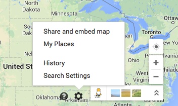
open Google Maps and click My Places on the
Settings Wheel at the bottom right of the screen (Figure 9-3).
In the screen that opens, click the Create Map button, followed by the “Create a new map” button (Figure 9-4).

Follow the instructions to import/upload the locations.csv file you just created, and voilà! You now have a custom map created with the waypoints you recorded with your GPS. You can add columns as well to your logged CSV file; spend some time experimenting with the NMEA string that you receive from the GPS module and adding it to your data values.
If you’d like to see the path created in Google Earth (useful especially if
you’ve utilized the gps module’s .fix.altitude function), there’s a bit more
work involved unless you are a Google Earth Pro user. If you’re not, you’ll
need to convert the data you’ve logged into a KML file. As it happens, you can
do that relatively easily with a Python script.
A KML file is a special sort of eXtensible Markup Language (XML) file used by
Google Earth to delineate landmarks, objects, and paths. It’s formatted with
opening and closing < > tags for different levels of information, such as
<Document> and <path> and even <LineStyle>. By parsing our locations
file line by line, we can create a descriptive KML file that can be recognized
by and opened in Google Earth. Because we know how the final file needs to look,
the parsing program can be written ahead of time, and you can just plug in your
log file when your rover has returned home.
The first thing you’ll probably have to do, however, is rewrite your GPS-logging
script to save the locations, with spaces separating the latitude and longitude
instead of commas (this has to do with line feeds, and parsing the file using
Python, and will save you hours of debugging later). If you prefer, write to two
files at once by adding a write line to the original script, writing to a
locations.log file as well.
Your final format_kml.py file should look something like this:
importstring#open files for reading and writinggps=open('locations.log','r')#f = gps.readlines()kml=open('locations.kml','w')kml.write('<?xml version="1.0" encoding="UTF-8" ?>\n')kml.write('<kml xmlns="http://www.opengis.net/kml/2.2">\n')kml.write('<Document>\n')kml.write('<name>Rover Path</name>\n')kml.write('<description>Path taken by rover</description>\n')kml.write('<Style id="yellowLineGreenPoly">\n')kml.write('<LineStyle><color>7f00ffff</color><width>4</width></LineStyle>\n')kml.write('<PolyStyle><color>7f00ff00</color></PolyStyle>\n')kml.write('</Style>\n')kml.write('<Placemark><name>Rover Path</name>\n')kml.write('<styleUrl>#yellowLineGreenPoly</styleUrl>\n')kml.write('<LineString>\n')kml.write('<extrude>1</extrude><tesselate>1</tesselate>\n')kml.write('<altitudeMode>relative</altitudeMode>\n')kml.write('<coordinates>\n')forlineingps:coordinate=string.split(line)coordinatelongitude=coordinate[0]latitude=coordinate[1]kml.write(longitude+","+latitude+"\n")kml.write('</coordinates>\n')kml.write('</LineString>\n')kml.write('</Placemark>\n')kml.write('</Document>\n')kml.write('</kml>\n')gps.close()kml.close()
The first part of this code simply opens the necessary files and then writes all of the necessary KML formatting to locations.kml to set up the file. Then the small five-line loop reads through the locations.log file and places the data into the KML file. Then the script finishes up the KML formatting and cleans up after itself by gracefully closing the input and output files.
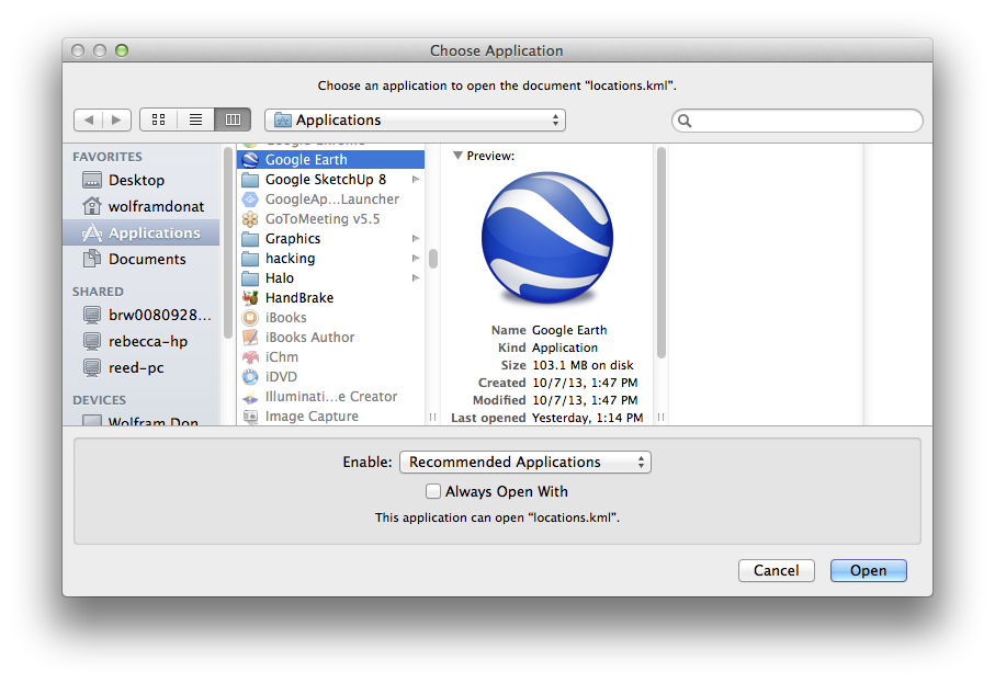
Your locations.kml file can now be viewed in Google Earth from any computer that has Google Earth installed. Right-click the file and from the Open With dialog box, choose Google Earth (Figure 9-5).
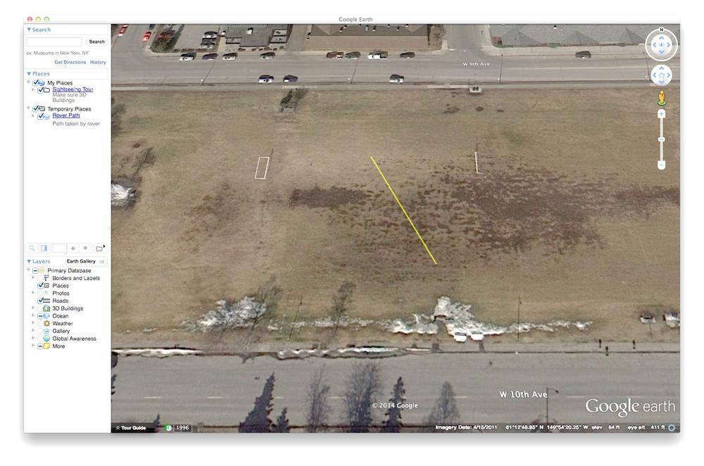
You should get a nice yellow path showing where your rover has been (Figure 9-6).
Of course, you can do tons of things with these location files, but one of the most interesting is to use them as waypoints in a preprogrammed route for the rover to follow. Plug in a sequence of points, and using the GPS module, your rover should be able to navigate to each of those locations and execute a preprogrammed sequence of events without any assistance from you. That, of course, is assuming that the terrain between point A and point B is navigable by the rover. Traveling between Flagstaff, AZ, and Cedar City, UT, for example, doesn’t take into account the rather large canyon that lies between those two cities. (If your rover can successfully navigate the Grand Canyon autonomously, I’d be very interested in seeing it. So would NASA.)
This is just an introduction to the things you can do with your GPS module. In the next chapter, we’ll take a look at adding sensors to the rover so you can do more than simply travel from point to point.