Chapter 9. Payloads

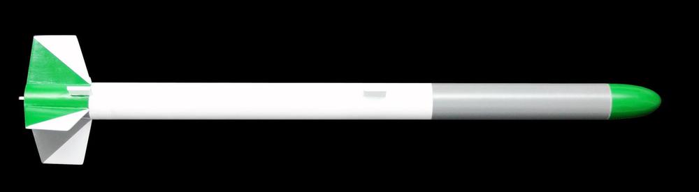
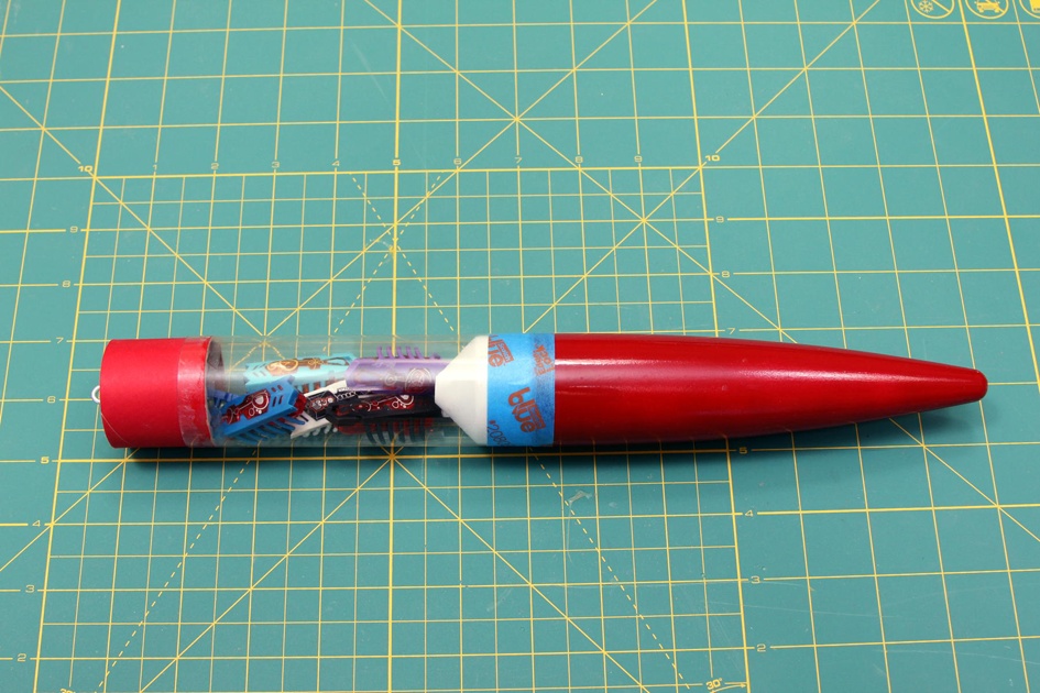
Flying the rockets we’ve seen so far is fun, but at some point you will want to step it up a notch and build rockets that carry something. It might be something whimsical, like some candy to pass out as “space candy” to the kids at a launch; it might be for a contest like the popular egg-lofting competitions; or it might even be an electronics payload to measure the altitude and acceleration of the rocket or the temperature and humidity in the atmosphere. Whatever it is you want to lift, you need a payload rocket.
Before we get too far into the planning stages, though, there is one rule about model rocket payloads that you need to be aware of. Model rockets are not allowed to carry live vertebrates as a payload. There is no scientific reason to pack a mouse into a model rocket. An egg is just as challenging technically, and the failures are entertaining instead of tragic. If it has a spine, it’s a spectator, not a payload. Insects are allowed; I can personally say that grasshoppers, crickets, and bees all fly quite well in model rockets. Better than eggs, in fact. I’ve never lost an insect, but I have scrambled a few eggs.
This chapter covers two payload rockets, giving you a good fleet of payload vehicles. One of the payload rockets is a Tinkertoy rocket that has lots of variations. We’ll look at two different boosters in this chapter, and another later, in Chapter 18. The chapter also shows how to build five different payload capsules for different purposes, and some obvious alterations that can be made on them for still other uses. You will find out everything you need to know to fly an electronic altimeter to find out how high a rocket really went; an egg for the challenge of lifting and recovering a delicate, heavy payload; and a camera to take high-definition video of a rocket flight.
Some of the rockets later in the book also have payloads, but they still depend on information from this chapter. Chapter 15 introduces high-performance rockets, and uses the same altimeter you will see in this chapter to figure out how high the rocket really goes. Chapter 18 shows two cluster rockets, both of which can carry payloads.
Liftoff Weight
Most of the rockets in the book list specific motors that will work in them. That works fine, because the weight and drag of the rockets were already known. Sure, there will be variations depending on how much effort you put into finishing your rocket, what kind of paint you use, and so forth, but those are not big enough differences to affect which motors will work.
Double the weight of the rocket by putting an egg in the payload bay, though, and things change. Your motor may not be powerful enough to lift the rocket. Worse, it may be powerful enough to lift the rocket, but not quite powerful enough to get it up to speed before it gets to the end of the launch rail. The result is called a land shark, where the rocket flops horizontal and powers off in a dangerous direction.
Or, perhaps the motor has plenty of power. The rocket lifts off, soars into the sky, and the delay charge begins to burn. The rocket reaches apogee, arcs gently, and turns over. The delay charge is still burning. The rocket screams to earth, impacting the ground. The ejection charge fires, deploying the parachute across the grass. That’s called a lawn dart, since the rocket can easily stick in soft ground like the old lawn dart toys.
Or maybe you get lucky and the parachute deploys a few dozen feet off of the ground. Just in time, right? Well, maybe. The rocket may be moving fast enough to shred the parachute or break or rip loose from the shock cord. Even if the parachute and shock cord survive, the shock cord can rip through the body tube of the rocket. That’s called a zipper.
I’ve seen all of these things happen. When you start adding payloads, you also have to start selecting the motors specifically for each flight.
There are three things to consider when picking a motor for a rocket:
- Is the motor powerful enough to lift the rocket?
- Will the rocket be traveling fast enough to be stable when it reaches the end of the launch rod?
- Will the delay charge deploy the recovery system near apogee?
Using Charts to Find the Proper Motor
The first two questions are really a mater of the thrust available for the rocket. If the motor has enough thrust, it will lift the rocket, and lift it quickly enough to reach an adequate speed for the fins to work before the rocket leaves the launch rail. It turns out that the thrust needed when using a 3-foot launch rail is 11 times the weight of the rocket. We’ll see why it is 11 times the weight of the rocket in Using Math to Cheat Mother Nature.
This means we need to know the thrust of the rocket motor. We should be able to get that from the motor’s label, right? A B6-4 motor delivers 6 newtons of thrust, after all. Well, yes, that’s the average, but most motors actually deliver quite a bit more thrust initially, during that first 0.13 seconds the rocket is on the launch rail. Take a look at the thrust curve for the Estes B6-4, shown in Figure 9-3.

You can see that the maximum thrust is about twice the average thrust. That lets the B6-4 motor lift a rocket that is twice as heavy as you would expect based on the motor designation alone. That’s also why you need to look at the thrust curve for the motor, not just the motor designation, when picking a motor for a payload rocket.
Thrust curves are available from several sources. Manufacturers have thrust curves on their websites, and sometimes even include them with the documentation that comes with a motor. You can also find a great summary of model rocket thrust curves at ThrustCurve.org. These files are generally designed for simulators, but you can see the thrust curves, too. Start with the Browser button on the main page, and navigate to the motor you would like to examine. There are a number of ways to find a particular motor, so I won’t describe a specific one here. Once you’ve selected a motor, you will see a page like Figure 9-4.

This page lists the maximum thrust, but you need to make sure that the maximum happens soon enough—or, at least, that the thrust reaches 11 times the weight of the rocket you want to lift soon enough. So what is “soon enough”? As a general rule, you want the maximum thrust in the first 0.2 seconds after ignition. That’s based on a 3-foot-long launch rod and an acceleration large enough to hit 30 mph by the time the rocket gets to the end of the rod. The time will vary with other launch rod lengths.
The only way to see if the maximum thrust happens soon enough is to look at the data. Click on the View Data icon on the right under Options. This particular motor has files for two simulators. It doesn’t matter which one you pick. Figure 9-5 shows the data for RockSim. It’s pretty similar to the curve shown in Figure 9-3.
Table 9-1 shows the maximum thrust for some common motors, including the ones used in this book. The delays are not shown, since the thrust does not change with the delay charge; a C6-0 and a C6-7 have the same thrust curve.

| Motor | Maximum thrust in newtons | Maximum liftoff weight (ounces) |
Estes 1/4A3 T | 5.0 | 1.6 |
Estes 1/2A3 T | 7.6 | 2.5 |
Estes A10 T | 12.6 | 4.1 |
Estes A8 | 9.7 | 3.2 |
Estes B4 | 12.8 | 4.2 |
Estes B6 | 12.1 | 4.0 |
Estes C6 | 14.1 | 4.6 |
Estes D12 | 33.3 | 10.9 |
Estes E9 | 19.5 | 6.4 |
Quest A8 | 11.1 | 3.6 |
Quest B4 | 14.4 | 4.7 |
Quest C6 | 15.5 | 5.1 |
Quest D8 | 28.9 | 9.5 |
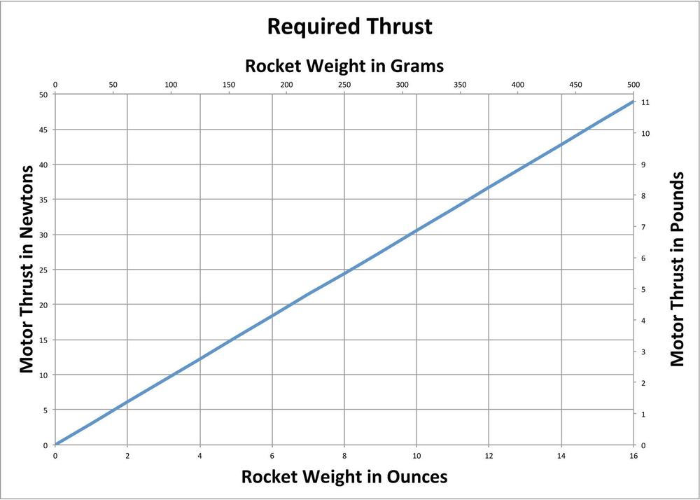
Thrust curves for model rocket motors are usually shown in newtons, but occasionally in pounds of force. Model rocket weights are usually given in ounces, grams, or kilograms. Figure 9-6 shows a chart that will let you quickly pick a motor based on the maximum thrust. Find the weight of the rocket along the horizontal axis, and then go straight up or down to the line. Follow the line to the left or right to read off the minimum required thrust in newtons or pounds that you need to safely launch the rocket.
For example, let’s say we’re getting an egg lofter ready to launch. Our handy kitchen scale tells us the rocket, fully loaded with a parachute, motor, and egg, weighs 9 ounces. Figure 9-6 has 8 and 10 ounces along the x-axis. Picking a point about halfway between them and following it up to the line, then left to the y-axis, we see that we need about 27 or 28 newtons of thrust to lift our rocket. That rules out many of the smaller motors, but the D12, with 33.3 newtons of maximum thrust, will work just fine.
What if you don’t know the exact weight of your rocket? A good estimate will work, too. This chapter shows the finished weight of each of the boosters and payload bays. Add in the weight of the motor and payload, and you have a pretty good estimate of the launch weight. You can get the weight of the motor from the manufacturer’s website. You can come up with a pretty good estimate for the weight of most payloads with some thought or a few Internet searches. For example, it’s not hard to use the Internet to find the average weight of a Grade A egg. True, recovery wadding and the parachute weigh something, too, but they don’t contribute much to the total weight of a rocket carrying a heavy payload.
Picking a Delay Time
Picking a delay time is a little trickier. We can ignore drag for the first fraction of a second of flight. It’s still there, but the average speed of the rocket on the launch rail is only about 15 miles per hour—not enough for drag to be a huge impact on the dynamics of the rocket. That changes as the rocket powers up to speed, though. Hebe, a high-performance rocket you will see in Chapter 15, can hit 500 miles per hour. That’s 33 times the average speed on the launch rail, and since the force of drag is proportional to the square of the velocity, that means Hebe is experiencing over 1,100 times more drag force at peak speed than the average aerodynamic drag force it experiences on the launch rail. A streamlined high-performance rocket like Hebe will not have the problems with drag that an irregular rocket like Nicomachus from Chapter 19 does. Hebe therefore needs a longer delay time than a rocket with more drag, even if you add enough weight so they weigh the same.
The most accurate way to pick a delay time is to fly the rocket and see what works. That’s a little hard on rockets and spectators, though, so we generally use simulations to pick the delay time. Simulations are not quite as accurate as the real thing, but they are close enough to pick reasonable ejection delay times. Simulations are covered in more detail in Chapter 14. For this chapter, each rocket will have a table showing what motor to use for various payload weights.
Using Math to Cheat Mother Nature
In Using Charts to Find the Proper Motor, we used a thrust-to-weight ratio of 11 to determine the safe launch speed for a rocket. Why that number? The answer comes from some basic physics. Understanding the physics will also help you cheat the system a bit, flying rockets that are not “safe” under standard launch conditions.
This section is a bit long to be a sidebar, but it does go into some mathematical details you can safely skip if you don’t find them interesting. Stick with Figure 9-6 and you will be fine.
Still here? OK, let’s look at the physics. After all, physics is phun!
Starting from rest, the distance a body travels under constant acceleration in a given amount of time is:
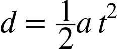
where d is the distance traveled, a is the acceleration, and t is the time. Traveling in a straight line, the speed after that amount of time is:

With a little bit of algebra, we can solve for the acceleration needed to reach a specific speed in a certain distance. Basically, we solve both equations for t, then set them equal to each other, and then solve for a:
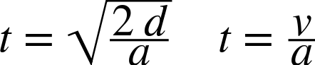


This gives the acceleration needed to reach a specific velocity in a given distance. Both simulations and experience from hundreds of thousands of model rocket launches teach us that a rocket needs to be traveling at about 30 miles per hour, or 13.4 m/s, for the fins to keep it stable in flight. A 36-inch launch rod is about 0.91 meters long. Substituting 13.4 m/s for the velocity and 0.91 meters for the length, we find the acceleration needed to launch a model rocket, which is 98.66 m/s2.
The thrust of a rocket motor is usually measured in newtons, which is a measure of force. Returning to basic physics, we have:

where F is the force, m is the mass of the object, and a is the acceleration. The acceleration from gravity is 9.8 m/s2, so the downward force on the rocket from gravity is 9.8×m newtons. The force needed to get enough acceleration to reach an appropriate launch speed by the end of the launch rail is 98.66×m newtons. The rocket motor must overcome both the force from gravity and the inertia from the mass of the rocket, so it needs 108.46×m newtons for a clean launch.
Another force comes from the weight of the rocket. While we sometimes use “weight” and “mass” interchangeably in everyday conversation, they are not really the same thing. The mass is the resistance of the object to movement, while the weight is the force exerted by gravity. The rocket weighs 9.8×m newtons, so the thrust-to-weight ratio is:

That’s where the thrust-to-weight ratio of 11 comes from.
That’s the physics, but we measure thrust in newtons and the weight of the rocket in grams or ounces. Of course, a gram is actually a unit of mass, so it does have to be converted into a force, but we’re stuck with grams as the “weight” on a scale because that’s the way scales are calibrated in the metric world. You convert newtons of force to grams of mass by dividing by the acceleration of gravity and then converting kilograms to grams, so one newton is the force exerted by 102 grams at the surface of the earth. Dividing by 11, a rocket with 1 newton maximum thrust can safely launch a rocket whose mass is 9.28 grams. The conversion for ounces is similar; a rocket motor delivering 1 newton of thrust can lift a rocket that weighs 0.327 ounces. You get the actual safe launch weight by multiplying 9.28 grams or 0.327 ounces by the actual maximum thrust of the rocket motor.
You might object that this is an approximation. There is friction from the launch rail and the air that we’ve ignored, and the motor doesn’t deliver its maximum thrust the entire time the rocket is on the launch rail. You could also argue that some rockets are more stable than others, and may not need as much speed, or may need more.
All those objections are valid. But both rocket simulations using computers and practical experience from hundreds of thousands of rocket flights show that this approximation is good enough. As long as you are within about 10% of the listed weight, your rocket should fly fine.
So why is this science important? After all, we know the answer: multiply the maximum thrust by 9.28 grams or 0.327 ounces. We could also stick with using Figure 9-6. Who cares about the details? But stop and think for a moment. What if the thrust-to-weight ratio is only 8, rather than 11? Does that kill the rocket design? Not necessarily; you may just need a longer launch rod! And, with the science to back you up, you know how to decide just how long that launch rod needs to be.
You may see people successfully launching rockets that seem to defy these calculations. The Ceres A booster, which we’ll meet later in this chapter, is one example. These numbers are based on a speed that works for almost any model rocket, even when wind speeds approach 20 miles per hour. That’s a moderate breeze, enough to move small branches, cause flags to flap, and raise small whitecaps on water. You probably won’t want to fly rockets in winds that high, since the chance of losing one goes up with the wind speed, but the rocket should still be designed to be stable at those speeds. After all, a gust of wind may hit just as you press the launch button, and you don’t want your rocket to become a land shark. Still, with calm winds and large fins, it’s possible to launch with a lower thrust-to-weight ratio. That’s where simulators and test flights become important. In general, don’t launch rockets unless they have a thrust-to-weight ratio of at least 11. For rockets with a lower thrust-to-weight ratio, or even rockets right at a thrust to weight ratio of 11, only fly in calm conditions.
What happens if the thrust-to-weight ratio is too low? If it is very low—below 1—the rocket won’t move at all. Beyond that, it all depends. If the thrust-to-weight ratio is so low that the rocket is not traveling fast enough for the fins to work, the rocket will be unstable. If the rocket is going fast enough for the fins to work, but is still going very slowly compared to the current wind speed, the rocket will weathercock, turning sharply into the wind. Exactly when these things happen depends on the actual thrust-to-weight ratio, the design of the rocket, and the wind speed. If you keep the liftoff speed to 30 mph or higher, launch in wind speeds of 20 mph or lower, and make sure the rocket is stable, the rocket should fly fine.
Juno Payload Conversion
Back in Chapter 3, we built our first solid propellant rocket: a great sport flier called Juno. You might also remember the basic stability rules from that chapter. Adding weight at the nose of a rocket makes it more stable. That means we can do a payload conversion on just about any model rocket. Let’s see how to do that with Juno.
Figure 9-1 showed Juno with the payload bay installed. Table 9-2 shows the motors you can use for the Juno payload conversion. Note that the motor selection depends on the payload weight. Heavier payloads require a shorter ejection delay.
| Motors | Approximate altitude | Payload weight |
A8-3 | 120–280 ft | 0–1 oz |
B6-4 | 390–660 ft | 0–1 oz |
C6-7 | 1,100–1,400 ft | 0–1 oz |
C6-5 | 690 ft | 2 oz |
Table 9-3 lists the parts you’ll need for the Juno payload conversion.
| Part | Description |
BT-50 clear payload tube | This is the clear plastic tube from the Estes Designer’s Special. Clear plastic payload tubes are also available separately from Estes and several other manufacturers. |
BT-50 tube coupler | Used to form the shoulder of the payload bay. If you are ordering parts, you can substitute a BT-50 balsa nose block for the tube coupler and balsa fin stock. |
1/8” balsa fin stock | This will be used to form a bulkhead at the base of the payload bay. |
Screw eye | You will need a small screw eye for the base of the nose section. These are available at hardware stores. |

Construction
Refer back to Chapter 3 for basic construction techniques, tools, and materials. That’s when you built Juno. If you built it without the snap swivel, start by adding one to the shock cord and parachute. That will let you quickly switch between the payload bay and the original Juno design.
Cut two disks from the 1/8” balsa stock. Each disk should just barely fit inside the tube coupler. Glue the disks together with the grain from one disk perpendicular to the grain from the other; this increases the strength of the disks. Glue the completed assembly into one end of the tube coupler.

Glue the tube coupler into the base of the clear payload tube. The tube coupler is 1” long; glue about 1/3 of it in the tube. Wood glue does not work especially well on the clear plastic payload tube. If you have some handy, use a small dab of epoxy instead. If you don’t have epoxy handy, rough up the portion of the inside of the clear plastic tube that will be glued to the tube coupler with sandpaper. That will give the wood glue something to embed itself in, so it won’t break free from the slippery plastic as easily.
Screw the screw eye into the bulkhead formed by the balsa disks, remove it, squirt some glue into the hole, and reinsert the screw eye.
That’s it for construction. Detach the nose cone from the rocket and slide it into the top of the payload tube, then attach the shock cord to the screw eye of this payload bay. You can use the same technique to convert just about any model rocket to carry a payload.

Flying the Juno Payload Conversion with an Altimeter
There really is no difference between flying Juno and flying the Juno payload conversion, other than any preparation you might need to do to get the payload ready. Here’s one example that might be both fun and interesting.
The MicroPeak altimeter from Altus Metrum is a tiny little thing, but it has capabilities that will surprise you. That’s the altimeter lying on the card to the left of the Juno payload bay in Figure 9-10. The battery is on the back side of the altimeter. It’s a barometric altimeter that finds the altitude of your rocket based on pressure changes, the same way many altimeters in airplanes work. That means you need to let the pressure in the payload bay change as the rocket flies. You can do that by drilling a 1/16” hole in the payload bay. In general, the hole should be at least one body tube diameter in length from the base of the nose cone, but the shoulder of the nose cone is long enough that it pretty much has to be anyway. I put the hole near the bottom of the payload bay, well away from the turbulence from the transition around the base of the nose cone.
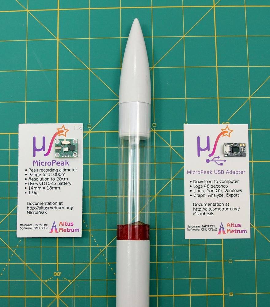
The altimeter itself is very easy to use. Just before the flight, flip the tiny switch on the altimeter. It will flash the altitude from the previous flight in decimeters using an LED. For example, if the pattern is 1 flash, 4 flashes, 2 flashes, and 1 flash, the maximum altitude was 142.1 meters. The device then flashes a series of short pulses, followed by a long pulse, and then settles down to an occasional flash to let you know it is on.
Drop it into the payload bay, stuff some cotton in to keep it from rattling around, and fly the rocket just like normal.
After the flight, turn the altimeter off and back on. Count the flashes. Right away, you know how high the rocket went.
Back at your desk, download the free software from http://www.altusmetrum.org/MicroPeak/ and install it on your computer. It will show you how to connect to the MicroPeak USB adapter and move the data from the flight computer to your desktop computer. Figures 9-11 and 9-12 show the flight data from the Juno payload conversion, flying on an A8-3 motor.

You can see some places where the altitude and speed seem to jump in an unreasonable way. This is normal with real sensor data. Most of the cause is the rocket itself bouncing around on the shock cord.

Before we move on to our next rocket, here’s a complete launch preparation checklist for the Juno payload conversion with a MicroPeak altimeter, and a launch checklist to use before each launch.
The Ceres Payload Rocket
Unlike the rockets built so far in this book, the Ceres payload rocket isn’t just one monolithic design. NASA rockets like the Saturn IB carried many different payloads, including the Earth-orbiting Apollo flights and ferrying astronauts to Skylab. Some of those same payloads were also carried on the Saturn V. The Apollo command service module and the lunar module flew on both the Saturn IB and Saturn V. We will follow suit here, with three boosters and five payload bays.
The boosters are the Ceres A, Ceres B, and Ceres C. They look pretty much the same. The external design is identical, with four large fins for stability and an 18"-long BT-60 body tube. The difference is the propulsion systems. The Ceres A flies on the same A, B, and C motors you have used on other rockets in this book, meaning that you don’t have to add to your existing stock of motors. The Ceres B uses D or E motors. That gives you a lot of power for heavy payloads or high flights. The Ceres C is a cluster rocket that uses three A, B, or C motors. It is covered in Chapter 18, where you will see why the cluster rocket with three C6 motors can lift even heavier payloads than an E motor, which has 33% more total impulse.
There are five payloads for these rockets. Any payload can be flown with any rocket. That’s a total of 15 possible combinations! Three payloads are general-purpose payload bays like the one on the Juno payload conversion. Two others are highly specialized payloads. One carries a small video camera, while the other carries an egg.
Unlike the rockets in the book, the payloads have descriptive or whimsical names. The texting generation will have no trouble seeing why the clear payload is called ICU or why the camera is called ICU2. For the non-texting generation… well, think about it a moment.

You can build any one of the Ceres boosters and the Thin Man payload bay with the parts in the Estes Designer’s Special. Table 9-4 lists the additional parts you will need to build all of the boosters and payload bays. All of the parts except the camera are usually available from http://jonrocket.com, although they are occasionally out of some of the balsa parts. You can also get the balsa parts from http://balsamachining.com, and pick up the other parts from http://estesrockets.com or other online stores. Complete parts lists for each booster are also given at the start of each construction section.
| Part | Description |
BT-60 body tube (2) | You only have one left in the Estes Designer’s Special. You will need one more for each booster you build. |
BT-70 body tube | One section will be used for the egg lofter, while a longer piece will be used for the Fat Man payload bay. |
BT-80 body tube | A small section will be used for the ICU2 payload. |
1/8” balsa fin stock | The supply in the Estes Designer’s Special will run short. Pick up another sheet from your local hobby store, or you can mail order a sheet when buying the other parts. |
BT-60 clear payload tube | This is used for the ICU payload bay. This is a larger version of the payload for the Juno payload conversion. You can find these individually, or get a package of several clear payload bays from http://estesrockets.com. |
BT-70 nose cone (2) | Get two of these. One is used for Over Easy and one for the Fat Man. The nose cone for Over Easy must be balsa; a plastic one will not work. |
BT60–BT70 transition (2) | This is the piece you see at the bottom of the larger payload bays that transitions from a BT-60 to a larger body tube. Get two, one for Over Easy and one for the Fat Man. The transition for Over Easy must be a balsa transition. |
BT-80 nose cone | For the ICU2 payload. You can get a second if you like, and make an even bigger version of the Fat Man payload. The nose cone for ICU2 must be balsa. |
BT60–BT80 transition | For the ICU2 payload. This must be a balsa transition. |
Y2000 mini camcorder | This is the camera for the ICU2 payload. Actually, any small camera will work. Do some shopping on the Internet and see if there is a newer one with features you like better. You will also need a micro SDHC memory card. You may already have one for something else. If you buy one, get a small one. A rocket movie doesn’t take a lot of space, and there is a risk of losing the camera, so you don’t want to spend a lot of money on a big memory card. |
Snap swivels | It’s possible to tie and untie the parachutes and shock cords as you switch payload bays, but it’s a lot easier to use snap swivels. You will need one snap swivel for the shock cord on each booster, plus one snap swivel for any parachutes you plan to use. |
Screw eye (5) | You will need a small screw eye for the base of the nose section for each payload you build. |
The Ceres A Booster
The Ceres A booster can lift any of the payloads, but it’s a fairly underpowered rocket for lifting payloads of any weight. Its main advantage is that the rocket can be built and flown with a single standard motor. With thrust-to-weight ratios running as low as 7.2, you should use a longer launch rod when available, and launch only on very calm days. That said, I have test flown the Ceres A with most of the payloads, including the Over Easy payload. All were flown with 3-foot launch rods. The Over Easy payload with the Ceres A booster has the lowest thrust-to-weight ratio in the book. Tables 9-5 through 9-9 list the recommended motors to use with the Ceres A for each payload.
| Motors | Payload weight | Liftoff weight | Approximate altitude |
C6-5 | 0 oz | 4.7 oz | 410 ft |
C6-3 | 1 oz | 5.7 oz | 270 ft |
| Motors | Payload weight | Liftoff weight | Approximate altitude |
C6-3 | 0 oz | 5.6 oz | 280 ft |
C6-3 | 1 oz | 6.6 oz | 220 ft |
| Motors | Payload weight | Liftoff weight | Approximate altitude |
C6-3 | 0 oz | 5.0 oz | 390 ft |
C6-3 | 1 oz | 6.0 oz | 270 ft |
| Motors | Payload weight | Liftoff weight | Approximate altitude |
C6-3 | 0.6 oz | 5.8 oz | 290 ft |
| Motors | Payload weight | Liftoff weight | Approximate altitude |
C6-3 | 2 oz | 7 oz | 180 ft |
Table 9-10 lists the parts you will need to build the Ceres A booster.
| Part | Description |
BT-60 body tube | Use the full 18"-long body tube. Some companies sell 34"-long body tubes. Cutting one in half and using 17” works fine, too. |
BT-20 motor mount | You can use a precut 2 3/4” motor mount tube, or cut your own from a longer piece of BT-20 body tube. |
3/32” balsa fin stock | The balsa wood will be used for the fins and for launch lug standoffs. |
1/8” launch lug | You will use two pieces, each 1” long. |
Engine hook | Use the shorter (2 3/4”) engine hook. |
Engine sleeve | You can use tape if none are available. |
1/8” shock cord | You will need about 30” of shock cord. |
Snap swivel | You will need one snap swivel for the shock cord. |
Construction
Refer back to Chapter 3 for basic construction techniques.
There are no body tubes to cut if you are starting with a precut 2 3/4” motor tube. If you are starting with a BT-20 body tube, cut a 2 3/4” piece from the tube for the motor tube.
The main body tube is an uncut 18” BT-60 body tube.
You will need four fins cut from 3/32” balsa and rounded on all edges except the root edge. Figure 9-14 shows the full-size fin pattern.

You will need two launch lug standoffs. Looking at some of the payloads, you can see that the body tube for the payload bay is larger than the body tube for the booster. The launch lug needs to be mounted 1/2” away from the body tube to allow space for the payloads. Cut two 1” x 1/2” standoffs from 3/32” balsa. Make sure the fin grain is parallel to the short side of the standoff so it runs from the body tube to the launch lug, as shown in Figure 9-15.
If you look closely at the recommended motor charts, you’ll notice that the Ceres A is a bit underpowered for some of the payloads. You will want to use a longer launch rod if one is available. Long 1/8” launch rods tend to be a little flexible, and can create rod whip, where the launch rod flaps back and forth violently as the rocket travels rapidly up the rod. If you have a long launch rod, it may be a 3/16"-diameter rod. Be sure and swap out the smaller launch lugs for 3/16” launch lugs if you plan to use a longer, 3/16” launch rod.

The motor mount is cut from one of the thick paper motor mount sheets in the Estes Designer’s Special. If you are buying individual parts, you can either buy BT-60 to BT-20 centering rings or cut your own from 1/8” balsa.
With the parts cut, it’s time to assemble the rocket. Start with the motor mount. It is assembled just like the motor mount for Juno, so we won’t go over it in detail. You may want to save the plastic engine sleeves for the Ceres C booster. Tape works well, too; just coat it with a layer of glue to add strength. That’s what you see in the assembled motor mount in Figure 9-16.

While the motor mount dries, use the fin guide in Figure 3-25 to mark the body tube for four fins and a launch lug. Attach the four fins flush with the bottom of the body tube. Attach a launch lug on a standoff two inches from each end of the tube. Set the assembly aside to dry.
Once the parts are dry, mount the motor mount in the base of the body tube, and attach the shock cord near the upper end of the body tube using the standard paper mount. Since you will be switching between a variety of payloads, use a snap swivel at the end of the shock cord.
That completes the construction of the booster. It is shown in Figure 9-17 with the completed Thin Man payload.

Flying the Ceres A
The Ceres A can be flown with any of the payloads described later in this chapter. The payload may require some changes in the launch checklist, but the booster itself is very standard. Here are the launch preparation and flight checklists for the Ceres A.
The Ceres B Booster
If you are only going to build one of the three boosters, build this one. The powerful D and E motors will lift all of the payloads well. The only downside is that D and E motors have age restrictions in some states, and you must use a launcher with a 30-foot launch wire if you’re igniting E motors. If you are under 18, you may need to get an adult guardian to buy the motors. Discuss the rocket and your plans with that adult, and plan some extra time to allow her to make the purchase if she agrees.
Table 9-11 through Table 9-15 list the recommended motors to use with the Ceres B for each payload.
| Motors | Payload weight | Liftoff weight | Approximate altitude |
D12-7 | 0-1 oz | 5.1-6.1 oz | 940-1,200 ft |
D12-5 | 2-5 oz | 7.1-10.1 oz | 400-740 ft |
D12-3 | 6 oz | 11.1 oz | 340 ft |
E9-6 | 0-1 oz | 5.9-6.9 oz | 1,500-1,800 ft |
| Motors | Payload weight | Liftoff weight | Approximate altitude |
D12-7 | 0 oz | 6.3 oz | 860 ft |
D12-5 | 1-2 oz | 7.3-8.3 oz | 460-700 ft |
D12-3 | 3-4 oz | 10.3 oz | 140-270 ft |
E9-8 | 0 oz | 7.1 oz | 1,500 ft |
| Motors | Payload weight | Liftoff weight | Approximate altitude |
D12-7 | 0-1 oz | 5.6-6.6 oz | 840-1,000 ft |
D12-5 | 2-4 oz | 7.6-9.6 oz | 440-660 ft |
D12-3 | 5-6 oz | 10.6-11.6 oz | 120-360 ft |
E9-8 | 0 oz | 6.5 oz | 1,700 ft |
| Motors | Payload weight | Liftoff weight | Approximate altitude |
D12-7 | 0.6 oz | 6.6 oz | 840 ft |
E9-6 | 0.6 oz | 7.3 oz | 1400 ft |
| Motors | Payload weight | Liftoff weight | Approximate altitude |
D12-5 | 2 oz | 7.8 oz | 640 ft |
E9-6 | 2 oz | 8.5 oz | 1200 ft |
Table 9-16 lists the parts you will need to build the Ceres B booster.
| Part | Description |
BT-60 body tube | Use the full 18"-long body tube. Some companies sell 34"-long body tubes. Cutting one in half and using 17” works fine, too. |
BT-50 motor mount | You can use a precut 3 1/4” motor mount tube or cut your own from a longer piece of BT-50 body tube. Note that these are the fatter motor mount tubes that are about 1” in diameter, not the smaller, roughly 3/4” motor mount tubes used in most other rockets in this book. |
1/8” balsa fin stock | The balsa wood will be used for the fins and for launch lug standoffs. |
3/16” launch lug | You will use two pieces, each 1” long. |
Engine hook | Use the longer, 3 1/4” long engine hook, not the shorter 2 3/4” engine hooks used elsewhere. |
Engine sleeve | You can use tape if none are available. |
1/4” shock cord | You will need about 30” of shock cord. |
Snap swivel | You will need one snap swivel for the shock cord. |
Construction
Other than using larger parts in a few places, the construction of the Ceres B is identical to the construction of the Ceres A. Refer back to Construction for step-by-step instructions. I’ll note the differences here.
The Ceres B uses 1/8” balsa for all fins and launch lug standoffs. In general, use 1/8” fin stock for D motors or above, or for cluster rockets that have a total impulse of 20 newton-seconds or more.
D and E rockets are also generally launched from heavier 3/16” launch rods, so you need to use the fatter launch lugs designed for 3/16” rails.
The motor mount is built just like the one for the smaller A to C motors, but it’s made from a slightly longer BT-50 body tube. The motor tube is 3 1/4” long. The engine hook is also longer (3 1/4”, as opposed to the 2 3/4"-long hook used in the Ceres A).
Finally, we use a thicker shock cord, moving from the 1/8” shock cord appropriate for smaller motors to a 1/4” shock cord.
This basically means the only thing that didn’t change is the main body tube. All of the other parts got a little thicker, a little longer, or a little fatter.
Figure 9-18 shows the motor mounts for the Ceres A, Ceres B, and Ceres C lined up for comparison.

Flying the Ceres B
The Ceres B can be flown with either D or E motors. The motor mount is designed for an E motor, which is a half-inch longer than a D motor. So how do you use a D motor?
There is a bright orange paper tube in the Estes Designer’s Special, as well as in many D–E motor mount kits. This is used as an adapter for D motors. Insert the adapter first, then the D motor, then fly like you normally would.
You should always save a few spent motors for various uses, such as supports when cutting body tubes. Another use is as an adapter—1/2” cut from an expended D or E motor case makes a fine motor adapter.

There is one other special consideration when flying the Ceres B booster.
E motors are large enough that everyone must be at least 30 feet from the rocket when it is launched. That includes the launch control officer, so you need a launcher with at least a 30-foot launch cord.
With that exception, flying the Ceres B is the same as flying the Ceres A. Launch preparation and flight checklists follow.
The Thin Man and ICU Payload Bays
These two payload bays are built identically. The only differences are the body tubes and nose cones used, and you can actually use either nose cone on either payload bay. These are also very similar to the payload conversion for Juno that we looked at earlier in this chapter.
Tables 9-17 and 9-18 list the parts required to build the Thin Man and ICU payload bays.
| Part | Description |
BT-60 body tube | Cut a piece from a larger tube. You have enough left in the Estes Designer’s Special for an 8” payload bay, which is what is shown. |
2 1/2” BT-60 nose cone | Use a lightweight nose cone for flights with the Ceres A. You can use a longer one with the Ceres B. |
1/8” balsa | Used to form a bulkhead at the base of the payload. |
BT-60 tube coupler | Used to form the shoulder of the payload bay. |
Screw eye | Used to attach the shock cord and parachute. |


Construction of the Thin Man and ICU Payload Bays
Begin by cutting the BT-60 body tube or clear payload tube to the desired length. There is nothing magic about the 8” length shown for the Thin Man; if you need a longer one for a specific payload, feel free to extend it. If you do extend the tube, though, stick with the Ceres B or Ceres C boosters—the payload is already a little heavy for the Ceres A.
The tube coupler in the Estes Designer’s Special is 3” long. If that’s the one you are using, cut it in half. You can use one piece for each payload bay.
Using 1/8” balsa, cut two disks that fit snugly inside the tube coupler. These will form a bulkhead at the lower end of the tube coupler, where we will eventually install a screw eye to attach the shock cord and parachute. Glue the two pieces together so the grain is perpendicular. Glue the finished assembly into one end of the tube coupler.
Glue about 1/2” of the tube coupler into the payload bay body tube. Wood glue works fine for the paper tube, but I recommend epoxy for the plastic tube. If you don’t use epoxy glue for the clear tube, be sure to rough up the inside with sandpaper so the glue will stick.
Once the bulkhead is dry, screw the screw eye into the center of the bulkhead, remove it, squirt some wood glue into the hole, and screw the screw eye back into place.
The nose cone does not get glued in. You will remove it to insert payloads into the payload bay. Do you recall how we added a payload bay to Juno, using the original nose cone as the nose cone for the payload bay? You can also do a reverse payload conversion with either of these payload bays, flying one of the Ceres boosters with just the nose cone.
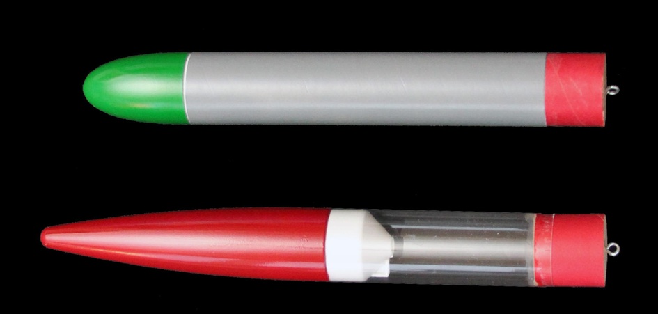
The plans show the short, squat nose cone on the Thin Man and the long, sleek nose cone on the ICU. You can certainly swap them, or use either one if you only build one of these payloads. That long nose cone really does look nicer, doesn’t it? It just looks more rocket-like. However, the short, round nose cone is actually the better one technically: it’s lighter, which is really important if you are using the Ceres A booster.
Flight Preparation
You will need to modify your flight preparation checklist to accommodate your payload. How you change the checklist depends on the particular payload you use, though.
The only special consideration for the payload bay is making sure the payload does not pop out at apogee. For light payloads, just make sure the nose cone is snug, adding tape around the shoulder of the nose cone if needed. For heavier payloads, wrap a strip of tape around the joint where the nose cone attaches to the body tube.
The Fat Man Payload Bay
The Fat Man payload bay is a little different from the ones we’ve built so far. This is the first payload bay that uses a tube size that differs from the rocket itself. It’s also why we added launch lug extenders to the rocket. The parts you’ll need to build this payload are listed in Table 9-19.
| Part | Description |
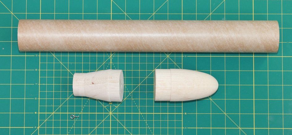
BT-70 body tube | BT-70 body tubes come in various lengths, depending on the source. The design shows 8” cut from a longer tube. |
BT-60 to BT-70 transition | This is a balsa piece that has a shoulder on each side, one for the BT-60 used as the main body tube of the booster, and one for the BT-70 payload tube. |
BT-70 nose cone | There are several BT-70 nose cones available from various manufacturers. This one is fairly short and light, but any will do if you use the Ceres B or Ceres C boosters. |
Screw eye | For attaching the parachute and shock cord. |
Construction
Cut the BT-70 body tube to the desired length. The design shown uses an 8” section of tube, but you can make it longer or shorter. Stick with the Ceres B or Ceres C boosters if you use a longer body tube, though. Like the Thin Man payload, this payload bay is already pretty heavy for the Ceres A.
Use wood glue to glue one end of the transition into the payload tube.
Screw the screw eye into the base of the transition—the part that will slide into the BT-60 body tube—then remove it, squirt glue into the hole, and screw it back in.
That’s it. The payload bay is ready for finishing.
While this version of the payload bay uses a BT-70 body tube, you can build a similar version using a BT-80 body tube. I’ve used BT-80 body tubes with rockets that carried iPhones to record data; see Chapter 7 of Building iPhone and iPad Electronic Projects (O’Reilly) for details.

Flight Preparation
As with the Thin Man and ICU payloads, modify your flight checklist as appropriate for the payload you are carrying. Secure the nose cone to the payload tube with tape for heavier payloads.
The Over Easy Payload Bay
The Over Easy payload bay is my personal favorite. It’s fun and different to build, and egg lofting is tons of fun at the launch site. Everyone wants to see what happened to the egg!
The parts list for the Over Easy (Table 9-20) is almost the same as that for the Fat Man, but construction is very, very different. The only additional part is some padding for the egg. The construction details discuss some alternatives.
| Part | Description |
BT-70 body tube | BT-70 body tubes come in various lengths, depending on the source. |
BT-60 to BT-70 transition | This is a balsa piece that has a shoulder on each side: one for the BT-60 used as the main body tube of the booster, and one for the BT-70 payload tube. |
BT-70 nose cone | Like the transition piece, the nose cone must be balsa. |
Screw eye | Used to attach the parachute. |
Some sort of padding | See the construction description for ideas. |
Over Easy Construction
The egg will be cradled in a cavity we will hollow out of the balsa nose cone and transition. The two pieces will actually butt up against each other; the payload bay tube is just used to hold them together.
Start by measuring the shoulder length of the two balsa parts. Mine had a total length of 1 13/16”. Yours may vary; take the time to measure the particular pieces you get. Cut a length of BT-70 body tube to match this length.
The next step works well with a thin kitchen knife like a paring knife. You are going to slice the balsa parts through the middle repeatedly until both the nose cone and the transition piece are cut into eight roughly equal parts. Figure 9-28 shows the first cut through the nose cone.
Warning: Watch Your Fingers!
About halfway through the cut, the wood will suddenly split. That’s fine as far as the cut goes. To avoid getting blood all over the balsa parts, think about how you are holding the knife. No fingers should be under the cutting edge of the blade. That way, when the part gives way and splits, you won’t suddenly force the knife into the cutting pad on top of your fingers.

Continue cutting each piece in half until there are eight total wedge-shaped pieces. Repeat the process with the transition piece. Figure 9-29 shows the final eight pieces of the transition piece.
You will be pulling these pieces apart and fitting them back together many times as you carve the egg cavity. Do yourself a favor and piece them all together now, then number the pieces on both the top and bottom of each end. You will carve the numbers off of the nose section; replace them with numbers inside the cavity as you carve. A rubber band is handy for holding the pieces together.

The size of the cavity depends a little on the thickness of the padding you select. I like to use the 1/8"-thick foam padding that frequently comes as packing material when I mail order parts. Thin bubble wrap works well, too. You can even use several layers of napkin or paper towel, but crumple the paper first so it doesn’t lie too flat. Whatever you intend to use, get it now and wrap the egg the way you intend to wrap it during flight.
Wrap the Egg
Rotten eggs smell so bad, they are a cliché for a bad smell. You don’t want that smell permeating your rocket after a mishap. Wrap the egg in plastic food wrap or seal it in a plastic bag before packing it. That way, if the egg cracks, the remains might stay safely separated from your rocket.
With the egg safely entombed, start carving the balsa parts to form a cavity for the egg. A hobby knife works well. You can get specialized blades for a hobby knife with the cutting edge on the side; that works even better. Test fit the parts frequently as you near completion to make sure you are carving off enough wood—but just enough! Figure 9-31 shows the parts once they are complete. You can, and should, assemble the entire capsule, holding it together with tape or rubber bands, before proceeding to the next step—gluing the parts back together. Make sure the egg fits perfectly before you glue anything.

Once the carving is complete and you have checked the fit, use wood glue to glue the parts of the nose cone and transition piece back together, then glue the transition piece into the bottom of the payload tube.
The balsa pieces I got from JonRocket.com also came with some 1/2” wood dowels. These can be used to strengthen the wood where the screw eye is inserted. I’ve build and flown a lot of egg capsules like this one, and have never used a hardwood dowel or had a screw eye pull loose, but it’s a good precaution. If you decide to use the dowel, drill a 1/2” hole about 1/2” into the base of the transition piece, then glue the dowel into place. Saw off any excess. Once the glue dries, install the screw eye just like you would in plain balsa.
Which brings us to the last step. Screw in the screw eye, remove it, squirt some glue in the hole, and then reinsert the screw eye.
All that’s left is finishing and painting to create a really nice egg lofting capsule.
Flight Preparation
There are some special steps for flying the Over Easy payload.
As launch day approaches, make sure you have a fresh egg that can be sacrificed for a test of your engineering prowess. I like to prepare the egg before leaving for the launch site, but you may have to prepare it in the field for contests. Make sure you have plastic wrap, padding, and tape for the packing job.
Wrap the egg in plastic wrap, then in the padding material you have selected. Insert the egg into the capsule, and place the nose cone in place.

The egg is a heavy payload. I’ve seen the shock of the shock cord pulling back on the capsule pop the nose cone off and eject the egg from the capsule, launching it in a ballistic return to earth. Splat! It’s the real-life version of Angry Birds. To avoid this mishap, be sure to fasten the nose cone securely to the capsule. Even though it’s a bit ugly, and spoils the effect of a nice paint job, I use a ring of tape around the nose cone joint.

After the launch, remove the egg and unwrap it. Are there any cracks? Congratulations! You’re ready for breakfast!
The ICU2 Payload Bay
This fun payload bay launches your very own spy camera into the sky. You can use it to create entertaining movies of your exploits, to do inexpensive aerial photography, or just for the sheer challenge of getting movies from a rocket.
There are a lot a ways to build this payload bay, so read through the description and think about your goals. The design shown is set up to create a movie of the rocket flight, pointing down along the tube of the rocket as it launches into the air. It points the camera down from the edge of the transition piece, so the transition piece needs to be big to give you room to mount the camera. The result is a dramatic movie of the rocket flight.
Other alternatives don’t need such a fat payload bay, and are much better at aerial photography. You can shoot sideways through the tube, then rig the parachute so the camera points down during the long, slow descent back to earth; or you could point the camera straight up. Either way you do it, use two parachutes: one for the camera pod and another for the booster. The result is a pretty boring liftoff and flight, but lots of frames on the descent. The movie isn’t that great—there is enough jerking around that you could make your audience sick. Or maybe that’s your goal. If it’s not, plan to grab still frames from the movie. This is a great way to get aerial photos.
Table 9-21 lists the parts you’ll need to build this payload. In addition to the standard tools and materials, a Dremel tool or other carving device will come in handy.

Construction
The camera will be housed in a hollow cavity in the transition piece. Figure 9-38 shows the finished carving.
Split the transition piece in half. Use the technique described in Over Easy Construction, being careful to hold the knife so you cut the wood, not your fingers.
Spend some time with the camera before you start to carve out the cavity. All cameras have different fields of view. You need to check the field of view on your specific camera so you can plan ahead and get exactly what you want in the frame. Personally, I like to see some of the rocket in a lift-off movie, so I plan the field of view so a bit of the fins and body tube are visible. That also lets you catch some of the smoke and flame from the rocket motor. Others don’t like to see the rocket at all. It’s your camera, and your choice.
Begin by taking a movie and raising the camera to two or three measured distances above something with a known dimension. Engineering paper, as seen in Figure 9-39, is a perfect choice.

Use the test movie to see what the field of view is at various distances. Plot the results on a piece of graph paper.
Cut out the field of view. Use it and the camera to decide on the specific location and orientation of the camera. Don’t let the camera’s normal orientation get in the way of a creative fit. In Figure 9-41, the top of the camera is on the lower side.

Once you decide on the proper position for the camera, trace the outline of the camera and the field of view on the transition piece. There are a number of ways to carve the cavity. A Dremel tool with a spherical cutting head works really well, but you can do the job with patience and a hobby knife. Work slowly, checking the fit as you go, until the camera sinks into the wood so that the lens is centered on the split in the wood. Then clean out the field of view for the camera.

The next step is to carve the cavity on the other side of the transition piece. You want them to match perfectly, so you need some way to form an image of the cavity you already have on the other piece of wood. A simple, effective way to do this is to put some colored powder in the existing cavity, place the two pieces together, turn the assembly over, shake gently, and remove the piece with the cavity. The colored powder will form the outline of the camera cavity on the other side. Trace it with a pencil and start carving, doing frequent test fits to make sure the pieces line up perfectly.
So where do you get colored powder? The spice cabinet works well. I used cinnamon, as seen in Figure 9-43.
Continue carving until the pieces fit together, cradling but not squeezing the camera. Depending on the orientation you pick, the corners of the camera may poke through, as they do in Figure 9-44. That’s not really a problem. The payload bay will work fine as long as there is enough wood left to hold the camera in place.

Don’t glue the pieces back together. The easiest way to hold the pieces together during flight is to put a ring of tape around both the upper and lower shoulders of the transition piece. A slightly higher-tech way of doing it is to countersink two screws, one in each shoulder.
Mount the screw eye in the normal way. Insert it, then remove it. Add some glue in the hole and reinsert the screw eye.
This is a large, heavy piece of wood, so it’s not a bad idea to use a hardwood dowel to reinforce the screw eye hole, as discussed in Over Easy Construction. The only peculiarity is that you can’t center the screw eye, since the crack in the wood runs right through the spot it would normally occupy. Instead, mount it in the center of one of the halves of the transition piece.
Measure the lengths of the shoulders on the transition piece and the nose cone. Cut a length of body tube just long enough to cover the shoulders. The nose cone and transition piece should just touch when inserted into the body tube. My body tube was 3” long, but measure before you cut in case there is some variation in the nose cone and transition piece you buy.
Glue the nose cone into the body tube, then finish as desired.
Flight Preparation for the ICU2
You will want to start the camera just before flight and turn it off immediately after recovery. Here’s the flight checklist for launching the ICU2 payload with the Ceres A or Ceres B booster.
Proceed with the launch in the normal way, then recover the rocket and turn off the camera as quickly as you can.
