Chapter 21. Air Rocket Glider
When an airplane goes into a dive, the lift of the wing or the tilt of the horizontal stabilizer causes the plane to pitch up at high speed, so it recovers. That doesn’t work well for a rocket, though, which would generate enough speed to spiral around in loops! Icarus, from Chapter 20, solves this problem by moving the motor well ahead of the wings and tail surface. Here, we’ll look at another approach.
Daedalus
There is another way to prevent the rocket glider from looping as soon as it leaves the pad, and that’s to change the shape of the aircraft. That’s the approach Rick Schertle used in a rubber band–launched glider he presented in MAKE volume 31 (also available online). The glider uses a really cool mechanism patented in 1939 by Jim Walker. When it is launched, the wings are folded next to the body of the rocket. Air pressure holds them in place. Once the aircraft slows down, the wings flip out and the aircraft glides to the ground. Later, Rick teamed up with Keith Violette, who built the air rocket launcher from Chapter 6. Their modified glider uses a plastic tube for the fuselage that allows it to be used with the air rocket launcher, and requires only a slight modification to the launcher to hold the wings back until launch. They are currently creating a kit based on this concept that uses plastic parts. We’ll take a look at how to build a similar air rocket glider here, using some of the techniques from Rick’s original rubber band–launched rocket and the concepts Rick and Keith developed to turn it into an air rocket glider.
While launching the glider from the air rocket launcher is loads of fun, you might also consider that the basic design would work for any sort of vertical launch. It’s pretty easy to see how this could be modified to use a solid propellant rocket motor.

The parts list for the air rocket version is shown in Table 21-1, and a list of tools and supplies you’ll need for this project is found in Table 21-2. The major parts are shown visually in Figure 21-2.
| Part | Description |
BT-50 body tube | Use a 12” piece cut from a longer tube. |
BT-50 nose cone | The nose cone shown is the BNC50Y from Balsa Machining. Other nose cones will work fine. |
BT-50 nose block | The nose block shown is a solid balsa plug fit to a BT-50 that is 1” long. Most of the time it’s fine to substitute a nose block made from a tube coupler capped on each end with a sheet of balsa, but this one is used as a structural component of the rocket. It doesn’t have to be a precise fit, so you can carve one from a block of balsa if you like. |
BT-50 tube coupler | This is used to tighten the fit so the body tube fits more snugly on the launcher. You can substitute tape if you don’t have a handy tube coupler. |
3/32” balsa plank | Used for the wings, stabilizer, and rudder. |
Screw eye | A small screw eye is used as an attachment point for the rubber band that moves the wings. |
Rubber band | Small rubber band, about 2 1/2” long and 1/16” thick. A #16 rubber band from an office supply store works well. |
Staples (2) | Use two staples for the attachment points for the rubber bands. You won’t need the stapler, just the staples. |
Music wire (thin) | A piece of thin, rigid music wire about 9” long. The diameter should be 1/16” or less, but not so thin it’s too flexible. I used 3/64” (0.047”) wire. |
Music wire (thicker) | A piece of thin, rigid music wire about 24” long. The diameter should be 1/16” or more, but not so thick it is difficult to bend. I used 1/16” wire. |
Aluminum soda can | We’ll cut the metal wing supports from an aluminum soda can. |
5/16” brass tube | This is used for the outside of the wing pivot. |
9/32” brass tube | This is used for the inside of the wing pivot. The exact sizes of the two brass tubes are not important, as long as one slides smoothly into the other. |
Clay | A small amount of modeling clay is used to weight the nose of the glider. There is some clay in the Estes Designer’s Special. |
| Tool | Description |
Dremel tool or similar with a cutting disk | This will be used to cut the metal parts. Be sure you have safety glasses, of course. |
Hobby knife | Used to cut the balsa and paper parts. |
Needle-nose pliers | Used to bend the wire. |
Drill | You will need a drill with a 1/16” bit and a 5/16” bit. |
Wood glue | Used to glue the rocket together. |
Epoxy glue | Used to glue the metal wing root supports to the root of the wings. |
Thick CA glue | Used to glue the staples to the balsa wings. Epoxy can be used instead. |
Light machine oil | A light oil, like WD-40, to lubricate the metal parts. |
Paint | Paint and brushes for finishing. |

I built and examined prototypes of the upcoming air rocket glider kit from Keith Violette and Rick Schertle while designing and building Daedalus. The premade parts for the wing rotation mechanism make their kit considerably easier to build than the scratch-built version from this chapter. On the other hand, Daedalus is a bit lighter in weight than the kit, and can be built from parts you may already have on hand after building other rockets in this book.

Construction
In many ways, the air rocket glider is built like most of the solid propellant rockets in this book. The nose cone, body tube, and fins could easily be used in a standard model rocket. Refer to Chapter 3 if you need more details on basic construction techniques, tools, and supplies. The only real difference between building Daedalus and building a standard solid propellant rocket is the wing rotation mechanism, so I’ll spend a lot of time describing how it is built.
Cutting the parts
The visual parts list in Figure 21-2 shows all of the balsa and aluminum parts precut. Let’s start by getting our parts to that state.
Cut a 12” section from a BT-50 body tube. This will be the fuselage of the aircraft.
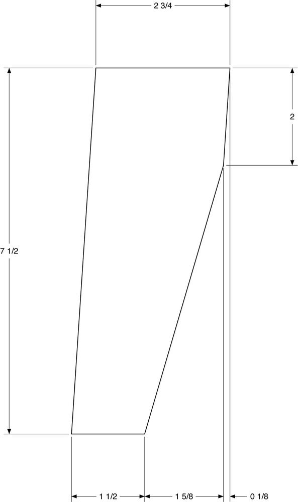
Use the patterns in Figures 21-4 and 21-5 to cut two wings and three pieces for the tail section from 3/32” balsa wood. The rudder and stabilizer are all the same size. Round all of the edges on the wings and tail surfaces except the root edges.

We’ll use a solid balsa nose block for strength where the wing attaches to the fuselage. These are available from several sources, including Balsa Machining and JonRocket. These generally come in long lengths; you will need to cut off a piece about 1” long. Some of them have a hole in the middle used to mount a hardwood dowel. If yours does, fill in the hole with the dowel that comes with the nose cone. We need a solid block of wood for the wing support.
This piece is going to be glued deep in the body tube, where minor mistakes are hidden from prying eyes, and where a dab of extra glue can fix small imperfections. In short, it doesn’t have to be perfect. If you don’t have a nose block, you can carve one yourself from a block of balsa. Whatever method you choose, you will need a 1"-long plug that fits reasonably snugly in the BT-50 body tube.
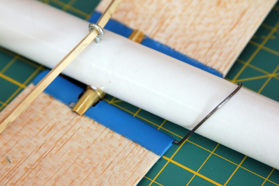
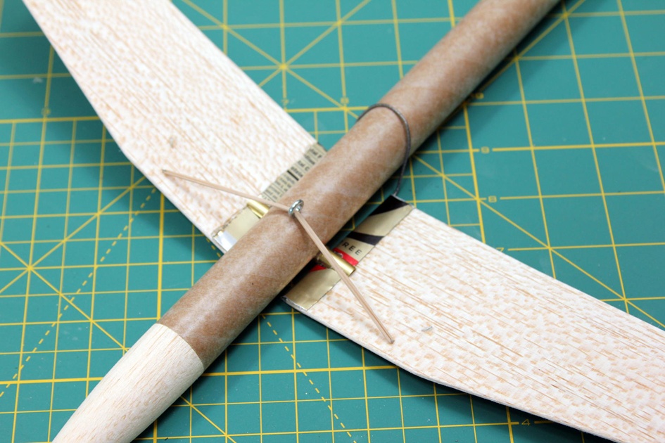
The wing needs to rotate in two directions to move from the launch configuration to the glide configuration. Take a look at Figure 21-6. It shows the detail view of the wing attachment. There is a wire running through the aluminum wing root support. This wire runs through a brass tube that slips through a second, slightly larger brass tube. The pair of brass tubes let the wing rotate from a position where the wing root is perpendicular to the body tube to a position where the wing root is parallel to the body tube. The wire lets the wing rotate from a folded position to an extended position. You can see the motion of the wings in Figure 21-7. They had to be held in place in the first three shots, since the rubber band really wants to snap the wings into the flight configuration!

Start the construction of the wing root by cutting the two metal supports from an empty soda can. Even if you’ve built a lot of rockets, you may not have worked much with metal. It might seem a bit intimidating at first, but it’s really pretty easy. We will be cutting pieces of metal from a soda can and from brass tubes. A Dremel tool with a cutting wheel works very well for this. Frankly, it’s easier to cut the metal parts than the balsa parts.
Wear Eye Protection
Be sure to wear eye protection while cutting the metal parts. The cutting process will throw off small bits of metal. They are usually not dangerous, and won’t hurt your skin, but you don’t want to get hit in the eye with one.
Mark the soda can near the base using a felt-tip marker and a piece of paper, just as you would mark a body tube before cutting it. Mark the can again 2 3/4” away from the first mark. Cut the can in both places using a cutting wheel, forming a 2 3/4"-long cylinder of aluminum.

Cut the cylinder lengthwise, then cut two 1"-wide pieces. This gives you two pieces, each 1” by 2 3/4”.

The wing pivot is cut from two brass tubes, the smaller of which should slide into the larger. While the parts list calls for 5/16"- and 9/32"-diameter tubes, any tubes that are about this size will work fine as long as one tube slides easily into the other. You can find these at well-stocked hobby stores, where you can test the fit of the tubes before buying them. Of course, if you do substitute different-sized tubes, you will need to adjust the various holes and patterns accordingly.
Cut a 1"-long piece from the larger brass tube. Clean off the cut edge, both inside and out, so it is free of burrs or rough edges. You can clean up the edges with sandpaper, a grinding wheel attached to a Dremel tool, or both. When you are finished, the smaller tube should still slide easily through the larger one.
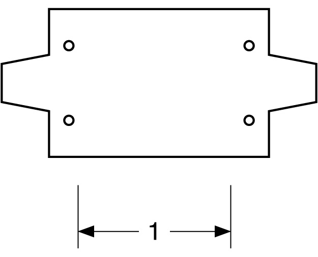
The smaller tube forms the base for the wings when they are deployed. The positioning of the holes for the wire that will eventually hold the wings in place and the angle of the cut where the wings will rest are both critical. The easiest way to get these right is to use a template like the one in Figure 21-10 and trace the edges on the brass tube with a permanent felt-tip marker. Use the pattern for drilling and cutting the part. The figure has a length marked that should be exactly 1” long in the final pattern. This lets you check for scaling problems caused by copying or printing. Be sure the pattern is exactly the right size. You can also get PDFs of perfectly sized patterns at the author’s website.
Drill the four holes for the wire using a 1/16” drill bit. Bits that small are flexible, and you’re drilling into a curved metal surface. Choke the bit up into the chuck until only a small part sticks out. This will keep it rigid enough to go through the brass tube where you want to drill.
Don’t try going all the way through and drilling the top and bottom holes with one pass. It is way too easy to drill the bottom hole in the wrong place that way. Drill the hole on one side, rotate the piece, and drill the hole on the other side. Once all four holes are drilled, check the piece carefully to make sure the holes are aligned with each other.

Finish this piece by grinding or sanding off any burrs or rough edges. Make sure the piece slides easily in and out of the larger brass tube.
Building the wing root
The balsa nose block provides strength for the wing root attachment. Glue the nose block firmly in place 2 1/4” from one end of the body tube. Use the same technique you would use to install a motor mount: first, apply the glue inside the body tube, and then use an old D motor or stick to quickly shove the nose block into place. Wood glue doesn’t dry fast, but it will lock the porous balsa nose plug inside the paper body tube with unexpected quickness, so don’t dawdle once you start this process. Dry fit all of the parts first, then apply the glue and quickly get the nose block shoved into place.
Once the glue sets, drill a 5/16” hole 2 3/4” from the end of the body tube and as close to the edge of the body tube as you can get it without drilling through the body tube. Figure 21-12 shows what the final result should look like.The hole should pass right through the nose block that you glued in place in the last step. Insert the 1"-long piece of 5/16"-diameter brass tube into the hole and glue it in place. It should be exactly centered in the hole, and absolutely must be perpendicular to the body tube.

Mark the body tube for four fins using the guide from Figure 3-25 in Chapter 3. The bottom fin mark should run right through the middle of the wing root tube, as shown in Figure 21-12. The fin guide on the top side will be used for the rudder and the screw eye that holds the rubber band in place. The two side fin marks will be used for the horizontal stabilizers.
Form the two wing root supports from the two pieces of aluminum cut from the soda can. Start by bending them in half to form a piece that is 2 3/4” long and 1/2” wide. Use a ruler or other thin, rigid tool to help you bend the aluminum. When you are finished, the aluminum pieces should have a gap between the top and bottom that is roughly 3/32” deep.

Test fit the wing root supports. They should form a slot along the root of the wing that is just large enough for 1/16"-diameter music wire to slide easily through the opening. Glue the pieces in place using epoxy glue.

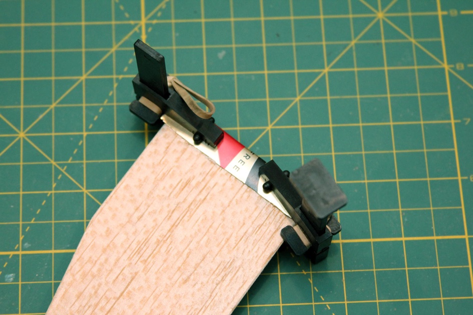
Clamp the wing root supports in place while the glue sets. You can do this with small modeling clamps like the ones shown in Figure 21-15, or you can lay a heavy book across the parts while they dry. Be sure and put some wax paper over and under the wing if you use a book—you don’t want to squeeze any glue out and glue the wing to the book or table!
While the glue sets, begin forming the wing root wire. This piece is bent from an 8 1/2"-long piece of music wire. This wire should be 1/16” in diameter or thinner, but not too thin. The wire will be much too hard to bend if it is thicker than 1/16”, and too flexible if it is very thin. I used 3/64"-diameter wire, which was a great compromise.
Using needle-nose pliers, slowly bend the wire using the pattern in Figure 21-16. It will be a lot easier to slide the wire into place if one end is about 1/8” longer than the other. That will let you concentrate on one side of the wing at a time.


Once the glue on the wings dries, use the cutting wheel to carve out a 1/4"-deep, 5/16"-long slot in each wing root, as seen in Figure 21-18. Insert a staple from the lower side of each wing to the top. Figure 21-18 shows a pattern for the slot and the exact location of the staples.

Working from the top side of the wing, bend the side of the staple farthest from the leading edge of the wing so that is is flush with the top of the wood. Bend the other end to form a small hook with the opening in the direction shown in Figure 21-19. This hook will be used to secure the rubber band that pops the wing into place. Glue the staples in place with CA glue or epoxy.

Insert a screw eye 2 1/2” from the end of the body tube and exactly opposite the wing root support. Slide the wire into place so it goes through the channels in the center of the wing root tube and the holes drilled in the smaller brass tube, which slips into place in the wing root tube. Run a rubber band through the screw eye, hooking the ends over the staples.
You can slip the nose cone into place, too, but don’t glue it! The nose block prevents any compressed air from getting to the front of the glider. Later you can drill a hole in the nose cone and insert any weight needed to balance the glider, hiding the weight inside the rocket rather than attaching clay to the outside. Leaving the nose cone unglued allows you to remove it later to adjust the weight.
Test the wing action by folding the wings down, then rotating them to the rear of the rocket. When you release the wings, they should pop into place.
Building the tail section
Once you are satisfied with the wing action, glue a tube coupler into the back end of the body tube. The BT-50 is just a bit too large for the PVC pipe used on the air rocket launcher. The tube coupler gives a snug fit so the expanding air shoots the rocket off the pad, rather than escaping through a gap between the body tube and launcher tube.
Glue the three tail pieces in place just as you would the fins for a rocket. These form the horizontal stabilizer and rudder for the airplane.
Finishing
You can paint Daedalus, but I do recommend leaving most or all of the wings unpainted. The paint can add quite a bit of weight, as we discussed when we were constructing Icarus.
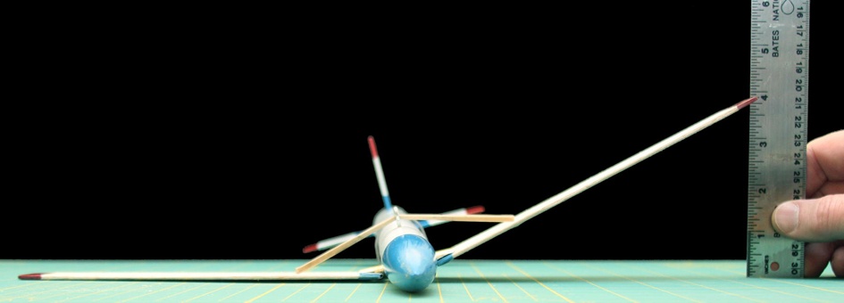
Once Daedalus is painted, check the alignment of the wings carefully. From the front, the wings should form a dihedral angle, which helps keep the plane level in flight. While this is usually specified as an angle, the easiest way to get it right is to lay one wing flat on a table and measure the height of the other. For Daedalus, one wing tip should be about 3 1/2” to 4” off the table when the other is lying flat. Make very small adjustments to the brass tube if they are not close to this range.
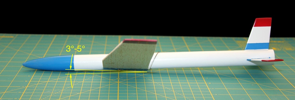
From the side, the wings should tip up about 3–5°. This forms an angle between the wing and tail that causes the plane to pitch up if it is going too fast. The combination of this angle and the dihedral is what causes the plane to settle into a steady glide. You can change this angle by bending the wing root wire. Bend the wire so the angle is closer to 0° from the vertical to increase the pitch angle; bend it so it is flatter to decrease the angle. During test flights, increase the angle if the glider tends to go into a nosedive and not pull out, even at high speed. Decrease the angle if the plane pitches up even at fairly low speeds, so it stalls and falls forward again.
Finally, add weight to the nose until the center of gravity is 1/2” from the rear of the wing root. This may not be perfect, but it will be close enough to start fine adjustments to the trim.
The wing holder
You know by now that those wings simply do not want to stay put when you fold them back along the body tube. It doesn’t take a lot of force to hold them in place—simply blowing on the wing will keep it folded—but the wings will pop into place as soon as all of the forces holding them back are removed.
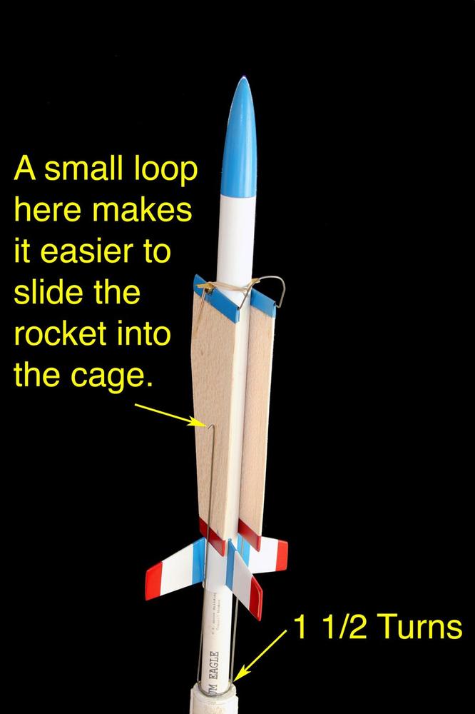
We need some way to keep them in place until the rocket picks up speed and clears the launcher. Cut a 24” piece of 1/16"-diameter music wire. Use needle-nose pliers to bend it 1 1/2 times around the air rocket launch tube. Bend the wire perpendicular to this ring, adding small loops at the end of the wire to make it easier to slide the wing past the top of the wire. You can slip this cage onto the launcher for a glider flight, and then remove it for regular air rocket flights.
Flying Daedalus
Balancing the glider
Just like Icarus, Daedalus must be trimmed before its first flight. Follow the tips in Balancing the glider from Chapter 20 to trim the aircraft, making sure it flies without tipping up and stalling or going into a nosedive. Add a small amount of clay to one wing tip so it will glide in a wide circle.
Now you’re ready for the first powered flight!
Powered flight
You saw how the wing cage holds Daedalus in place until launch time. Once the rocket picks up enough speed to clear the launcher, air pressure will hold the wings in place. As the rocket slows at apogee, the air pressure will no longer hold the wings in place, and they will pop out, turning the rocket into a glider.
Daedalus is a bit heavier than Icarus, so it will descend a bit quicker. It will also behave better in the wind, though.
Air rockets can be launched at angles up to 30° from the vertical. Daedalus cannot. If you launch Daedalus at an angle, it might travel in an arc, never slowing enough for the wings to deploy! It is very important to launch Daedalus vertically so it slows to a stop at apogee, allowing the wings to deploy.
Try to fly Daedalus in a large, flat grassy area. Keep in mind that you can’t predict which way it will glide, so you should be in a fairly large open area.
This is a very fun aircraft to fly. Since it’s an air rocket, there isn’t much time between flights. It may not fly as high as Icarus, but over an hour of flying, it just might be in the air longer because it takes so little time to get it ready for another flight.