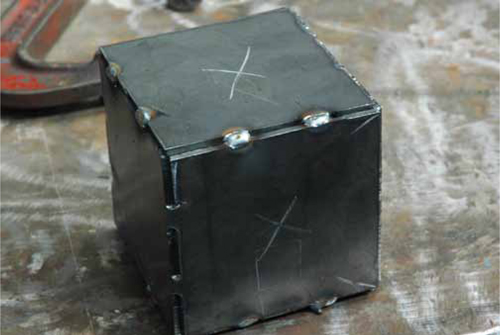
This project is going to further your practice with the metal–inert gas (MIG) welder and plasma cutter. If no plasma cutter is available, you can use an oxygen-acetylene torch. The idea here is to learn some basic layout techniques with steel and removed material in certain areas so that you are able to bend them easily. Welding in this project is minimal, but you’ll get great practice with the torch and see how workable steel is when designed properly. Figure 15.1 shows a completed bent and welded cube.

FIGURE 15.1 Bent and welded cube.
• 10-gauge steel
• Hand tools and clamps
• An angle grinder
• A plasma cutter or oxygen-acetylene torch
• A MIG welder
1. Place a piece of 10-gauge sheet metal on your cut table or hanging over the edge of your welding table.
2. If you would like to make a cube that is 6 in on each side, make your piece of steel at least 18 × 24 in. You are going to lay out the cube in a T formation as in Figure 15.2.
3. Using a straight edge and the plasma cutter or torch, set up to cut along the outside of your T as in Figure 15.3.
4. When it’s all cut out, you should have a shape like that in Figure 15.4.
5. Along the lines inside your T (the edges of each square side), cut slices approximately 1 in long, leaving short connecting bits of steel ¼ in wide.
6. When you get these cuts completed, hammer off any slag on the backside of the cut with a slag hammer as in Figure 15.5.
7. Grind along the edges of your steel to remove any sharp edges or other slag.
8. Using C-clamps or a vice, as in Figure 15.6, hold the sides of your cube, and start to form the bends by hand.
9. Because you cut away material along the bend lines, the bending should be quite easy, and you don’t need to worry about them being straight.
10. Continue bending as shown in Figures 15.7 and 15.8.
TIP: If you have trouble bending any part of this cube, try using an adjustable wrench to get extra leverage, as shown in Figure 15.9.
11. When all the sides are bent close to where you want them, use C-clamps to hold the cube together for your welds, as shown in Figure 15.10.
12. Make a series of welds like those shown in Figure 15.11 that match the small material that is bent around each corner.

FIGURE 15.2 The 6-in square sides of the cube positioned in the form of a T. Each side is marked with an X.

FIGURE 15.3 Cutting the outside, nice and straight.

FIGURE 15.4 Cut out the T.

FIGURE 15.5 Cleaning the cuts.

FIGURE 15.6 Using a vice to hold the sides of the cube.

FIGURE 15.7 Bending progress.

FIGURE 15.8 Bending progress.

FIGURE 15.9 Adjustable wrench for leverage.

FIGURE 15.10 Clamped cube.

FIGURE 15.11 Welding the seams.