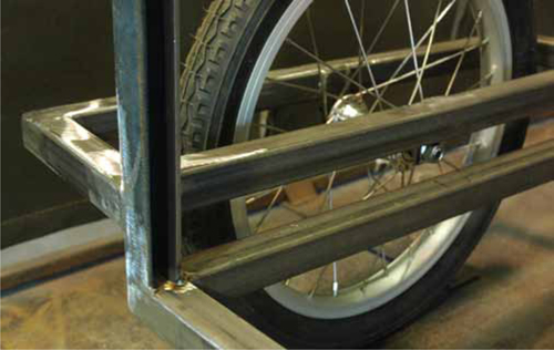
This project is going to require using some extra pieces and parts, and introduce some extremely useful fabrication basics. The basic platform of this cart could be modified to work with a number of different-sized bicycle wheels and even could be outfitted to work as a bicycle trailer. Figure 20.1 shows the framework with wheels before adding the plywood panels.

FIGURE 20.1 Garden cart.
• 1- × 1- ×  -in angle stock
• 1- × 1- × 0.083-in square tubing
•  - × 1-in flat stock
• ¾-in pipe
•  -in round stock
• Bicycle wheels
• Hand tools
• A grinder
• A metal–inert gas (MIG) welder
1. To start off, draw a rectangle to the dimensions of the cart platform on your welding table. My base is going to be 30 × 22 in.
2. Figure 20.2 shows square tubing cut with mitered corners at 45 degrees within my 30- × 22-in box.

FIGURE 20.2 Square-tubing base.
NOTE: When the square-tube frame is welded, it will be the first of your projects to have a hollow airtight space. Because welding has such high heat, it can rapidly expand air within your work, causing problems. Before you weld the frame, drill two ¼-in holes in it for safety.
3. When welding a frame such as this, it may help to reposition the piece so that you get the best weld position. Figure 20.3 shows how I’ve rotated the work so that I can weld in a flat/horizontal position rather than vertical.

FIGURE 20.3 Moving the work for ease of welding.
4. Before the next steps, grind all welds smooth on your frame, leaving the inside corner welds the way they are. Inside corners are difficult to grind without special tools, and they add a lot of strength.
5. For the front of the garden cart, I want to make a sliding door. To do this, I’ll use steel to make a channel to accept  -in plywood that can be lifted out. I want the front height of the cart to be 10 in, so the rail can be about 9 in. Cut four sections of flat stock and angle stock to make two of the pieces, as shown in Figure 20.4. Space the material apart using ½-in rod.

FIGURE 20.4 Pieces of the channel.
6. Make short weld beads along the seam between the flat stock and angle stock.
7. With one side of the channel square, you want to put a 5-degree pitch on the other end to give the cart a sloping handle. Using an adjustable square, scribe a 5-degree line 9 in away from the other end of the channel, and cut it using a cut disk on an angle grinder, as shown in Figure 20.5.

FIGURE 20.5 Cutting the channel.
8. With both pieces of channel cut the same, arrange them on the front edge of the cart base with the channel openings facing each other, as shown in Figure 20.6. Tack weld them in place.

FIGURE 20.6 Channel ends.
9. Cut two lengths of angle stock, perpendicular on one side and with a 5-degree cut on the other side to make the supports for the back of the handle, as shown in Figure 20.7.

FIGURE 20.7 Rear supports.
10. Cut two lengths of square tubing to about 4 ft long to make up either side of the handle. You don’t want to have exposed openings in the tubing for an outdoor project, so cut four 1-in squares of 1-in flat stock and weld them to the ends, as shown in Figure 20.8 (don’t forget to drill a hole to let hot gas escape). Grind the squares smooth to give the appearance of a solid piece of steel.

FIGURE 20.8 Ground and welded ends of tubing.
11. Set the lengths of tubing on the front and rear supports of the garden cart (making sure not to cover the top of the channel), and tack weld them in place.
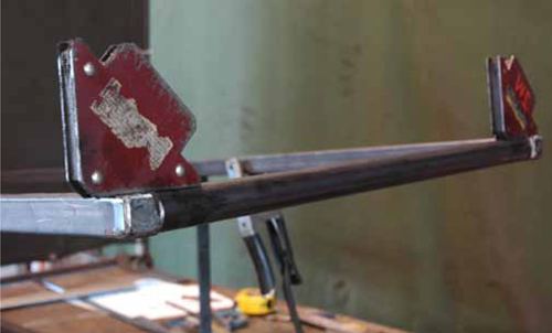
12. Cut a length of pipe to be used as the end of the handle. On my cart, it’s 20 in long. I used magnets to position it while I tacked it in place, as shown in Figure 20.9.

FIGURE 20.9 Ready to tack the handle in place.
13. Weld all the tacks you’ve made so far, taking measurements to make sure that things are staying straight, and then grind the visible welds smooth, as shown in Figure 20.10. Make sure to weld the inside corners where the square tubing meets the angle on the handle and the cart base. These corners are very strong, and the welds will be hidden from view.

FIGURE 20.10 Progress!
14. Next, you need to make the supports for the wheels. There’s quite a bit of flexibility here for different-sized wheels and to raise and lower the overall height of the cart.
15. For the wheel support, I made a P-shaped frame that supports the axle from above and spans the whole length of the cart. The P-shaped frame is shown tacked together in Figure 20.11.

FIGURE 20.11 Wheel support.
16. To add some style, I cut my front and rear pieces of tubing at 5 degrees to match the slope of the handle. It’s subtle, but it looks pretty nice when completed.
17. The wheels I am using for my cart are 16-in front wheels with a solid  -in axle. The width between axle nuts is 3
 in, so the space between the wheel-support frames needs to be at least 4
 in to make room for the dropout tabs.
18. After making sure that the frames are square, weld all corners, and fill in the open square ends using 1-in squares of flat stock.
19. To make the dropout tabs, cut four 2-in lengths of flat stock.
20. Find the center of these tabs, and center punch  in up from one end, as shown in Figure 20.12.

FIGURE 20.12 Center-punched tabs.
21. Drill these all out using a  -in drill bit to accept the axle.
22. After drilling, use a cutoff disk to cut slightly angled openings to the  -in hole from the bottom of the tap, as shown in Figure 20.13.

FIGURE 20.13 Angled cuts in the dropouts.
23. Mark the center of the P-shaped wheel support frame, and clamp each dropout tap here on the inside of the frame. Align the top of the tab with the top of the frame tubing to get the same height.
24. Use a  -in rod across the whole cart to check alignment of the tabs. Figure 20.14 shows me using an adjustable square to make sure that the dropouts are perpendicular to the cart frame.

FIGURE 20.14 Checking for square.
25. Weld along all the seams of the dropout tab.
26. Mount the wheels to the frame so that you can check for alignment and ground clearance. Figure 20.15 shows me measuring the height from the ground to achieve my desired cart-sitting angle. This angle slopes the handle back toward the user slightly so that when it’s picked up, the support won’t rub on the ground.

FIGURE 20.15 Measuring for the support.
27. The support can be made out of any type of material, but I’m going to hand bend a length of  -in round stock, as shown in Figure 20.16. I probably wouldn’t be able to do this to ½-in round stock, but
  -in round stock is just workable enough.

FIGURE 20.16 Bending the  -in round.
28. Using magnets, position your support at the rear of the cart (Figure 20.17), and weld it to the frame.

FIGURE 20.17 Rear support.
29. Go through the frame, and double-check that all the pieces of the frame, handle, and wheel supports are welded and ground (where appropriate). Figure 20.18 shows a detail of some of these welded connections.

FIGURE 20.18 Welded connection detail.
Because the cart created in this project is for outdoor use, I highly recommend a nice coat of outdoor-rated paint (or better yet, powder coat). Follow the instructions in Chapter 12 to thoroughly clean your metal, and give it a nice coat of primer and two or three coats of paint. Remove the wheels for these steps.