6.3 iFlow Example
In this section, we’ll demonstrate how to build an iFlow using an example scenario. Let’s assume that you need to build an iFlow to pick up a sales order information file from a folder in the local file system and deliver it to another folder (in the same file system) via SAP PO. For this scenario, the iFlow and all necessary repository objects will be created with SAP NetWeaver Developer Studio.
6.3.1 Creating Products, Software Components, Business Systems, and Technical Systems in the SLD
We want to provide a complete overview of working locally within SAP NetWeaver Developer Studio without using the Swing client. Let’s start by creating the supporting SLD artifacts. This includes a new product, three software components (SCs), and two technical and business systems. To create these SLD artifacts, follow the steps ahead for your particular tasks. For all of the following tasks, begin by navigating to the SLD via http://<host>:<port>/sld.
Create Product
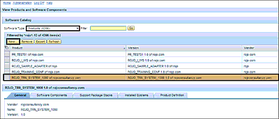
To create the product, follow these steps (see Figure 6.17):
- From the landing page of the SLD, select Products from the Software Type dropdown.
- Click the New button.
-
Follow the wizard, and provide the following information:
- Name: “ROJO_TRN_SYSTEM_1000”
- Vendor: “rojoconsultancy.com”
-
Instance Name: “IN_Rojo_Trn_System_1000”
Figure 6.17 Products Created in the SLD
Create Three Software Component Versions
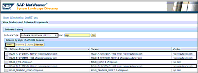
To create the SWCVs, follow these steps (see Figure 6.18):
- Select the Software Component Versions tab.
- Select the New… option.
-
Follow the wizard, and provide the following information as the names of your SCs:
- ROJO_A_SYSTEMA_1000
- ROJO_B_SYSTEMB_1000
- ROJO_PI_SYSTEMPI_1000
Figure 6.18 Software Components Created in the SLD
Note
You’ll need to create dependencies between the SCs. The SC ROJO_PI_SYSTEMPI_1000 should have dependency on ROJO_A_SYSTEMA_1000 and ROJO_A_SYSTEMB_1000.
Create Two Technical Systems
To create the technical systems, follow these steps:
- From the SLD landing page, select the Technical Systems tab.
- Select the New Technical System option.
-
Follow the wizard, and use the following attribute values for the first Technical System:
- System Type: Standalone
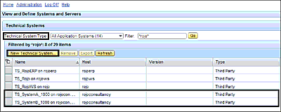
- Technical System Identification: “TS_SystemA_1000”
- System Host Name: An appropriate company domain name (e.g., “rojoconsultancy.com”)
-
Repeat both previous steps for the second technical system, and use the following attribute values:
- System Type: Standalone
- Technical System Identification: “TS_SystemB_1000”
- System Host Name: An appropriate company domain name (e.g., “rojoconsultancy.com”)
The resulting technical systems are shown in Figure 6.19.
Figure 6.19 Technical Systems Created in the SLD
Create Two Business Systems
To create the business systems, follow these steps:
- From the SLD landing page, choose the Business Systems tab.
- Select the New Business System option.
-
Follow the wizard, and use the following attribute values for the first business system:
- System Type: Third Party/Other
- System: “TS_SystemA_1000”
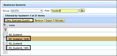
- Name: “BS_SystemA_1000”
-
Repeat both previous steps for the second business system, and use the following attribute values:
- System Type: Third Party/Other
- System: “TS_SystemB_1000”
- Name: “BS_SystemB_1000”
The resulting business systems are shown in Figure 6.20.
Figure 6.20 Business Systems Created in the SLD
6.3.2 Importing SLD Objects into the ES Repository in SAP NetWeaver Developer Studio
Switch back to the SAP NetWeaver Developer Studio start page launched earlier, and follow these steps to import all the necessary objects created in the SLD:
- Switch to the Enterprise Service Browser perspective, and log on to SAP NetWeaver AS Java.
- Import the SWCV from the SLD into the Enterprise Service Browser.
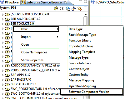
- Right-click on the view of the Enterprise Service Browser, and select New • Software Component Version (see Figure 6.21).
- Select the Import from SLD radio button. You’ll be presented with a list of SWCVs from which you can choose the SC that you previously created and named ROJO_A_SYSTEMA_1000.
- Repeat the previous two steps for the SCs named ROJO_B_SYSTEMB_1000 and ROJO_PI_SYSTEMPI_1000.
Figure 6.21 Steps to Import Software Components from the SLD
6.3.3 Create Enterprise Service Repository Objects
The next objects that need to be created for this scenario include namespaces, data types, message types, service interfaces, message mappings, and operation mappings.
To create all of these objects, click on the view of the Enterprise Repository Browser, and select the appropriate object to be created.
Create Three Namespaces
Create three namespaces in the ROJO_A_SYSTEMA_1000, ROJO_A_SYSTEMB_1000, and ROJO_PI_SYSTEMPI_1000 SCs created earlier to hold the sender system, receiver system, and common objects, respectively. Then, follow these steps:
- Right-click on the appropriate SWCV.
- Choose the Open Namespaces option from the resulting context menu.
-
Under the Namespace List, use the Add button to add a new namespace (see Figure 6.22).
Figure 6.22 Creating Namespaces to Hold ES Repository Objects
-
Add the namespaces according to Table 6.1.
SWCV Namespace ROJO_A_SYSTEMA_1000 urn:rojoconsultancy:training:systema:
salesorderROJO_B_SYSTEMA_1000 urn:rojoconsultancy:training:systemb:
salesorderROJO_PI_SYSTEMPI_1000 urn:rojoconsultancy:training:systempi:
salesorderTable 6.1 List of Namespaces and Corresponding Software Components
- After the namespaces have been created, save your changes.
Note
When creating or adding objects, SAP NetWeaver Developer Studio might prompt you to specify the change list underneath which the new objects will be kept for activation purposes.
Create Two Data Types
Two data types will be created, one for the sender system and one for the receiver system. Follow these steps:
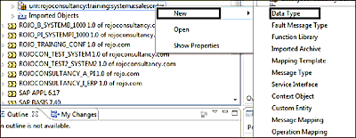
- Right-click on the urn:rojoconsultancy:training:systema:salesorder namespace in the A SWCV.
- Select New • Data Type from the dropdown (see Figure 6.23).
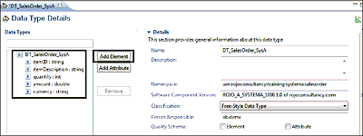
- Click on the Add Element button, and enter the information for the sender data type structure (DT_SalesOrder_SysA; see Figure 6.24).
- Click the Finish button, and save the object after creating the data structure.
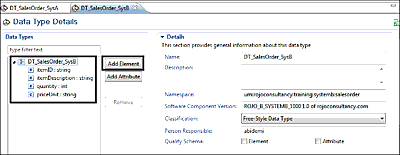
- Repeat the preceding steps to create the receiver data type in the urn:rojoconsultancy:training:systemb:salesorder namespace contained in the B SWCV, with the DT_SalesOrder_SysB receiver data type structure (see Figure 6.25).
Figure 6.23 Creating a Data Type for the Message Structure
Figure 6.24 Data Structure for System A
Figure 6.25 Data Structure for System B
Create Message Types
Create sender and receiver message types using the data types created earlier. Follow these steps:
- Expand the urn:rojoconsultancy:training:systema:salesorder namespace under the ROJO_A_SYSTEMA_1000 SC.
-
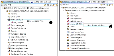
Right-click on the Message Type object node, and select the New Message Type option (Figure 6.26 1), which opens a new wizard.
Figure 6.26 Creating ES Repository Objects from SAP NetWeaver Developer Studio
- Name the message type “MT_SalesOrder_SysA”, and select appropriate data types using the Browse button. Select the DT_CustomInfo_SysA data type.
- Repeat the preceding three steps to create the receiver message type in the namespace that was created earlier (urn:rojoconsultancy:training:systemb:salesorder). The new message type can be named “MT_CustomInfo_SysB”.
Create Two Interfaces
To create sender and receiver service interfaces in the ES Repository, follow these steps:
- Expand the urn:rojoconsultancy:training:systema:salesorder namespace under the ROJO_A_SYSTEMA_1000 SC.
- Right-click on the Service Interfaces node and select the New Service Interface option (refer to Figure 6.26 2).
- In the new screen that appears, give the new service interface the name “SIOA_CustomInfo”, and click on the Finish button.
- Select the Definition tab.
- Select the Input node, and click on the Add Input Message button.
-
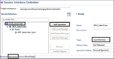
Use the Browse button to select the appropriate message type. In this case, you need to use the message type that was created earlier and named MT_SalesOrder_SysA. The attribute Type needs to be set to the value Asynchronous, as shown in Figure 6.27.
Figure 6.27 Service Interface Definition for the Sender System
- In the Overview tab and Advanced group, the service interface needs to have the Attribute category set to the value Outbound.
- Adjust other settings for the service interface as shown in Figure 6.27.
- Repeat the preceding steps to create the receiver service interface in the urn:rojoconsultancy:training:systemb:salesorder namespace created earlier and the SC named ROJO_B_SYSTEMB_1000. Name this new interface “SIIA_CustomInfo”. Furthermore, in the Overview tab and Advanced group, the service interface needs to have the Attribute category set to the value Inbound.
Create Message Mapping
A simple message mapping is created in this scenario for demonstration purposes. The source fields are mapped to the target fields in a one-to-one manner. Follow these steps:
- Within the ROJO_PI_SYSTEMPI_1000 SC, expand the urn:rojoconsultancy:training:systempi:salesorder namespace. Use the context menu on the Message Mapping node, and select the New Message Mapping option.
- In the new screen, provide a name for the new mapping. In this case, use the name “MM_SystemA_To_SystemB_SalesOrder”. Click on the Finish button.
-
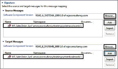
In the subsequent screen, under the Overview tab and Signature group, assign the appropriate message types for the source message and target message. Click on the Browse button to select the message types (Figure 6.28).
Figure 6.28 Message Mapping with Source and Target Messages
- Select the Definition tab to specify the message mapping (Figure 6.29). In this tab, you can implement the mapping or specify how to transform the source and target message types. All the fields are mapped one on one, except for the priceUnit in the Target field, which needs to be mapped using a concatenation of amount and currency in the Source fields. The mapping of the priceUnit field is shown at the bottom of Figure 6.29.
Figure 6.29 Message Mapping with Concatenated Fields
Create Operation Mapping
To create an operation mapping, follow these steps:
- Within the ROJO_PI_SYSTEMPI_1000 SC, expand the urn:rojoconsultancy:training: systempi:salesorder namespace. Right-click on the Operation Mappings node, and select the New Operation Mapping option.
- In the new screen, provide a name for the new mapping. In this case, use the name “OM_SystemA_To_SystemB_SalesOrder”. Click on the Finish button.
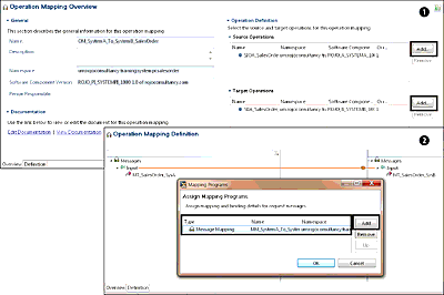
- Under the Overview tab, select the Operation Definition group, and click on the Add button to specify the source and target service interfaces (Figure 6.30 1).
- Navigate to the Definition tab, and select the mapping program (or message mapping) to be used between the source and target messages. Double-click on the line (on the function sign) connecting the source to target message input.
- When the new window pops up, click on the Add button.
- Under the Type column, select Message Mapping.
- Under the Name column, select the message mapping created earlier (Figure 6.30 2).
You’re now ready to create the different ES Repository artifacts that are required for your iFlow, so it’s time to activate these objects. Note that only after a successful activation will the objects be committed and become available in the ES Repository.
Figure 6.30 Operation Mapping with Outbound and Inbound Service Interfaces
Activating ES Repository Objects
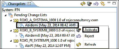
All the newly created or modified ES Repository objects (from the previous sections) are grouped under change lists. A different change list is created for each SC. Given that we’ve been dealing with three SWCVs, we can also expect three different change lists. Activate the change lists in each SC via the following steps (see Figure 6.31):
- Switch to the Change List Explorer view.
- Right-click on each change list name, and select the Activate option.
- Repeat the previous step for the other change lists.
Figure 6.31 Activating Change Lists for Repository Objects
With all the change lists activated, you’ve finished the repository work, and all objects created can be used for configuration when creating the iFlow.
6.3.4 Create Directory Objects: Import Business Systems and Create iFlows
In this section, the objects that have been created previously in the Enterprise Service Browser perspective will be used to create the iFlow. The steps discussed ahead will be used to create, configure, and deploy an iFlow and its supporting objects.
Importing Business Systems
In this scenario, business systems that have been created will be imported from the SLD. Follow these steps to import the business systems:
- From the SAP NetWeaver Developer Studio, switch to the SAP Process Integration Designer perspective.
-
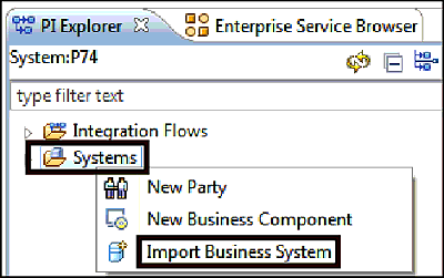
In the PI Explorer view, right-click the Systems folder, and select Import Business System (Figure 6.32).
Figure 6.32 Importing Business Systems from the SLD
- A new screen appears, in which a list of business systems from the SLD is presented. Select the desired business systems (in this case, BS_SystemA and BS_SystemB), and click on the Finish button.
Creating an iFlow
The iFlow will be created for the end-to-end exchange of messages between file systems. Follow these steps:
- Right-click on the Integration Flows folder in the PI Explorer view, and follow the wizard to create the iFlow.
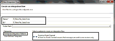
- In the Name and ID fields, enter “IF_FiletoFile_SalesOrder”.
-
In the New Integration Flow window, click on Enterprise Integration Patterns under Categories, and then select the Point-to-Point Channel pattern (Figure 6.33).
Figure 6.33 End-to-End File Scenario with the Point-to-Point Enterprise Integration Pattern
- Configure the Sender and Receiver systems by using the context menu on each and selecting the Assign System menu item. Choose BS_SystemA_1000 for the sending system and BS_SystemB_1000 for the receiving system.
- Assign a service interface to the sending and receiving systems by right-clicking on the Interface icon and choosing the Assign Interface (F4) option. For the sending system, select the SIOA_SalesOrder service interface that was created in Section 6.3.3.
- Configure the sender communication channel by right-clicking on the channel adapter on the sender side and selecting the adapter type (File) by using the Browse button.
-
Specify the name of the channel, as shown in Figure 6.34. Further communication channel attributes can be configured in the Adapter-Specific, Modules, and Identifiers tabs and are self-explanatory.
Figure 6.34 Configuring Settings for the Sender Channel
- Some useful attributes to fill in with values include the Source Directory and File Name, under the Adapter-Specific tab (see Figure 6.35 1).
- Furthermore, because you’re dealing with an asynchronous interface from the sender system, ensure that the sender communication channel has the Quality of Service (QoS) set to Asynchronous. To do so, go to the Adapter-Specific tab and then the Processing subtab. Set the QoS attribute to Exactly Once. In addition, set the polling interval to 10, and set the processing mode to Delete.
-
Configure the receiver communication channel by following the same steps as for creating the sender channel (see the two previous steps, and see Figure 6.35 2 for an example setup for the receiver communication channel).
Figure 6.35 Source and Target Directories in the File System
-
Configure the mapping by right-clicking on the connecting lane between the sender and the receiver, and selecting Add Mapping. The mapping artifact is added in the flow. Right-click on the mapping object, and choose the Assign Mapping option from the context menu. Select the operation mapping created earlier. The completed iFlow should look like the screen shown in Figure 6.36.
Figure 6.36 Completely Configured iFlow with Different Components
-
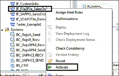
Save and activate by right-clicking on the iFlow created in the pallet and selecting the Activate option (Figure 6.37).
Figure 6.37 Activating the Configured iFlow
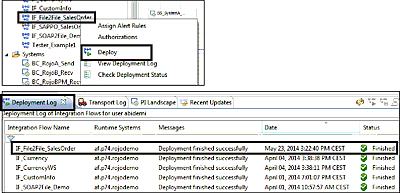
- Deploy the iFlow by right-clicking on it and selecting the Deploy option. After the iFlow deploys successfully, your console should look like the one shown in Figure 6.38 when in the Deployment Log tab.
Figure 6.38 Deploying iFlows and Viewing the Deployment Log
Finally, the iFlow scenario is ready for testing.
6.3.5 Testing the iFlow Scenario
To test the scenario that you’ve just created, follow these steps:
- Create an XML file with the name specified in the sender channel. In this case, the file needs to be called “SalesOrder.xml”, as previously indicated in Figure 6.35 1. Note that the content of the file also needs to match the structure of the service interface called SIOA_CustomInfo, which was created in Section 6.3.3. An example file is presented in Figure 6.39.
- Place this XML file in the source directory, as shown in Figure 6.35 1.
- After about 10 seconds, the file should be picked up from the source directory and be created in the target directory.
Figure 6.39 Sample XML Message Being Sent from the Source File System
6.3.6 Monitoring the Scenario
After you’ve placed a test file, it’s time to see how your iFlow processes the message during runtime. There are several ways to monitor the scenario. Message and channel monitoring can be performed via the traditional Monitoring Home, but for the purposes of further exploring what is possible in SAP NetWeaver Developer Studio, we’ll instead use the monitoring capability available from SAP NetWeaver Developer Studio. For message monitoring, follow these steps:
- Switch to the SAP PI Runtime perspective.
- Right-click on the iFlow that you previously created and named IF_FiletoFile_SalesOrder.
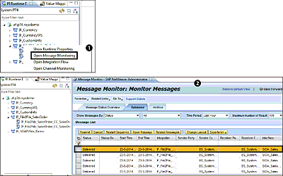
- In the context menu of the selected iFlow, select the Open Message Monitoring option, as shown in Figure 6.40 1.
- The messages processed are displayed in the monitor. You could also use the Open Message option to verify the message content 2.
Figure 6.40 Opening Message Monitoring from the SAP PI Runtime Perspective
