13.6 Exercise: SAP Business Rules Management
This exercise will help you get started with the creation of business rules in SAP PO. In this exercise, you’ll learn how to translate a functional requirement into an SAP BRM DC, which you’ll then implement using the Rules Composer.
For that purpose, we’ll extend the purchase order business use case introduced in Chapter 10. Let’s first see what requirements you’ve received from the process expert. Before a purchase order is sent by Reader’s Paradise to its supplier, Book Fountain, the purchase order must be validated against a set of business rules.
The process expert has provided you with the required input (see Table 13.3) to define the business rules in SAP BRM. The combination total amount of a purchase order and priority level (1 is low, 2 is medium, and 3 is high) assigned to the order should result in manual or automatic approval. This check is performed before an order is sent to the supplier. The business has also requested that you provide maximum flexibility in terms of changing the values driving this approval criteria. This is a common business use case that you might encounter when implementing SAP BPM applications running on top of SAP PO.
13.6.1 Exercise Solution Approach
After analyzing the requirements provided by the process expert, you decided to translate the approval criteria for this process step into a business rule DC containing a decision table, which in turn will be executed via a flow ruleset. The decision table will support the input from the business process. Table 13.3 shows the content your new decision table should contain.
| Purchase Order Amount | Priority Level | Approval Needed? |
|---|---|---|
| 1000 | 3 | NO |
| 10000 | 3 | NO |
| 100000 | 3 | YES |
| 1000 | 2 | NO |
| 10000 | 2 | NO |
| 100000 | 2 | YES |
| 1000 | 1 | NO |
| 10000 | 1 | YES |
| 100000 | 1 | YES |
| 1000 | 0 | YES |
| 10000 | 0 | YES |
| 100000 | 0 | YES |
Table 13.3 Decision Table
We’re assuming the following to be true for this exercise:
- You have access with admin rights to an SAP PO installation (sandbox or development system).
- SAP NetWeaver Developer Studio is installed locally on your development PC.
- You have a good understanding of XML and XSD.
13.6.2 Exercise Step-by-Step Solution
We’ll go through the following high-level steps (covered in more detail ahead) to create the business rule in SAP PO:
- Create the Rules Composer DC locally in SAP NetWeaver Developer Studio without the SAP NetWeaver development infrastructure.
- Define the rules input and output parameters by adding a new XML schema to the SAP BRM DC.
- Define aliases for the XML schema.
- Create a flow ruleset (to group all business rule components in one set).
- Create a decision table.
- Configure a rule flow (to graphically represent the business rule as a flow).
- Test the business rule.
Create Rules Composer Development Components Locally
To create the Rules Composer DC locally in SAP NetWeaver Developer Studio without the SAP NetWeaver development infrastructure, follow these steps:
-
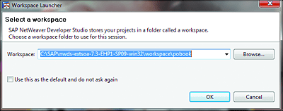
Start SAP NetWeaver Developer Studio, and select or create a new workspace (Figure 13.23).
Figure 13.23 Selecting a Workspace in SAP NetWeaver Developer Studio
-
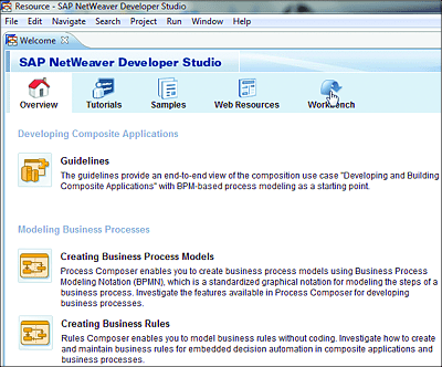
From the SAP NetWeaver Developer Studio Welcome page, click on Workbench (Figure 13.24). This is an optional step that is only applicable when you’re working with a brand-new workspace.
Figure 13.24 SAP NetWeaver Developer Studio Welcome Page
-
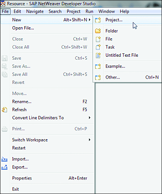
Create a new project via File • New • Project (Figure 13.25). In the dialog box that appears, choose Rules Composer and expand the folder.
Figure 13.25 Creating a New Project in SAP NetWeaver Developer Studio
-
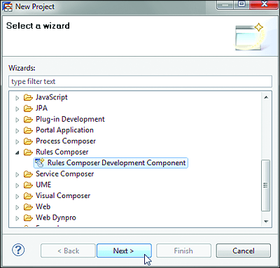
Click on Rules Composer Development Component, and click on Next (Figure 13.26).
Figure 13.26 New Rules Composer DC Wizard
-
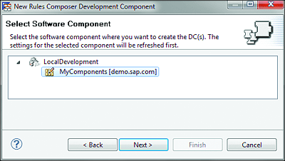
In the window that appears, choose the SC in which you want to create the DC. For this exercise, use the default local SC. Under the LocalDevelopment node, select MyComponents [demo.sap.com] (Figure 13.27). Click on Next.
Figure 13.27 Local Software Component Wizard
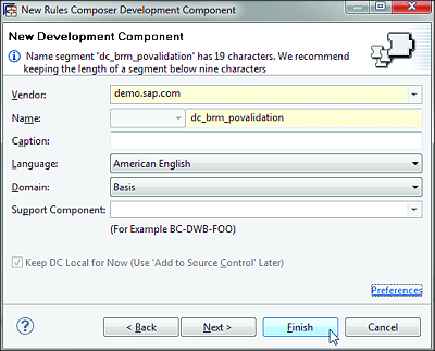
- In the screen that appears, enter “dc_brm_povalidation” in the Name field, accept the default values for the other fields, and click on Finish (see Figure 13.28).
Figure 13.28 Local DC
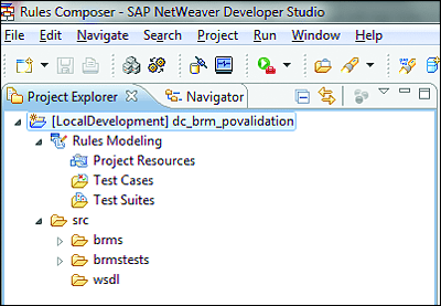
The result of this exercise is that you should see the dc_brm_povalidation DC in the Project Explorer view (see Figure 13.29). Click on it to expand its contents.
Figure 13.29 Rules Composer DC in SAP NetWeaver Developer Studio
Define the Rules Input and Output Parameters
To define the rules input and output parameters by adding a new XML schema to the SAP BRM DC, follow these steps:
-
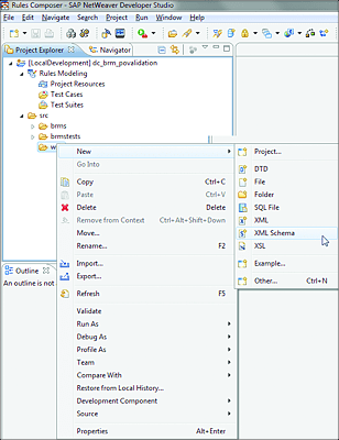
Navigate to the src folder, right-click on the wsdl subfolder, select New, and click on XML Schema (Figure 13.30).
Figure 13.30 Importing the XML Schema in SAP BRM DC
-
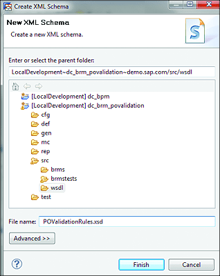
Enter the file name for the new XML schema (“POValidationRules.xsd”), and click on Finish (Figure 13.31).
Figure 13.31 Create New XML Schema Wizard
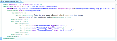
- Copy and paste the XML source shown in Listing 13.2 into the window that appears for the newly created XSD, as shown in Figure 13.32. Press (Ctrl) + (S) when you’re done.
<?xml version="1.0" encoding="UTF-8"?>
<xs:schema xmlns:xs="http://www.w3.org/2001/XMLSchema"
xmlns="urn:rojoconsultancy:sap:po:brm:validation" targetNamespace="urn:rojoconsultancy:sap:po:brm:validation">
<xs:element name="OrderApproval">
<xs:annotation>
<xs:documentation>This is the root element that carries the input and
output of the business rules</xs:documentation>
</xs:annotation>
<xs:complexType>
<xs:sequence>
<xs:element name="OrderAmount" type="xs:int" />
<xs:element name="Priority" type="xs:int" />
<xs:element name="ApprovalNeeded" type="xs:boolean" />
</xs:sequence>
</xs:complexType>
</xs:element>
</xs:schema>
Listing 13.2 POValidationRules.xsd
Figure 13.32 POValidationRules.xsd
Define Aliases for the XML Schema
To define aliases for the XML schema, follow these steps:
-
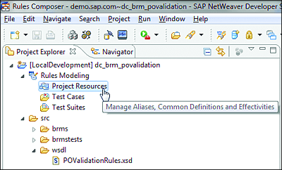
Navigate back to Rules Modeling, select the Project Resources folder, right-click, and select Open (Figure 13.33).
Figure 13.33 SAP BRM Project Resources
-
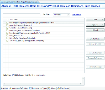
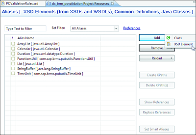
Select the Aliases tab, and from the upper-right menu, click on Add • XSD Element (Figure 13.34 and Figure 13.35).
Figure 13.34 Aliases Wizard: Project Resources
Figure 13.35 Aliases Wizard: Creating a New Alias from the XSD Element
-
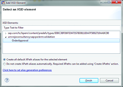
From the wizard, select OrderApproval under the namespace urn:rojoconsultancy:sap:po:brm:validation, accept the default values, and click on Finish (Figure 13.36).
Figure 13.36 Aliases Wizard: Selecting the XSD Element
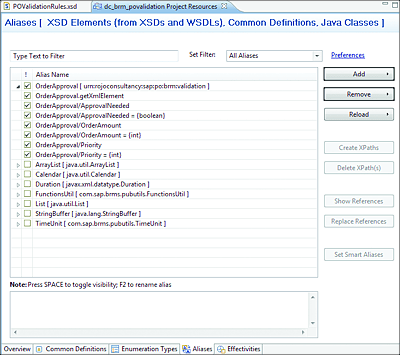
- In the next window, select all entries in the list prefixed with OrderApproval, and press (Ctrl) + (S) when finished. The final result is shown in Figure 13.37.
Figure 13.37 Aliases Wizard: Selecting Aliases from the OrderApproval
Create Flow Ruleset
To create a flow ruleset (to group all business rule components in one set), follow these steps:
-
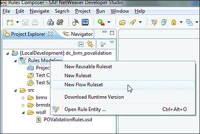
Select Rules Modeling, and then click on New Flow Ruleset, as shown in Figure 13.38. Enter “POValidationFlowRuleset” as the name of the new flow ruleset. Save your work by pressing (Ctrl) + (S).
Figure 13.38 Creating the New Flow Ruleset
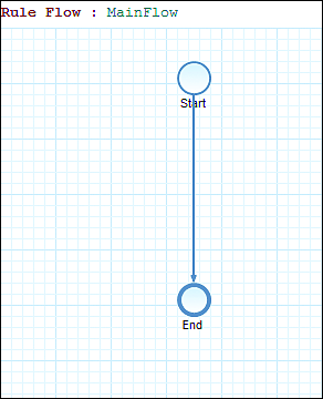
- Open the folder structure under the new flow ruleset to explore its contents. Notice that there is a basic flow rule created automatically when you open the Rule Flows tab. It should look like the one shown in Figure 13.39. We’ll come back to the configuration of that rule flow in the “Configure Rule Flow” section.
Figure 13.39 Rule Flow: MainFlow
Create Decision Table
To create a decision table, follow these steps:
-
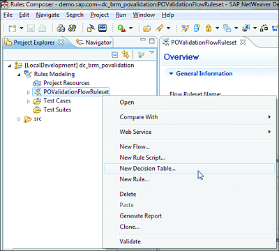
Select the new flow ruleset POValidationFlowRuleset, right-click on it, and select New Decision Table, as shown in Figure 13.40.
Figure 13.40 New Decision Table
-
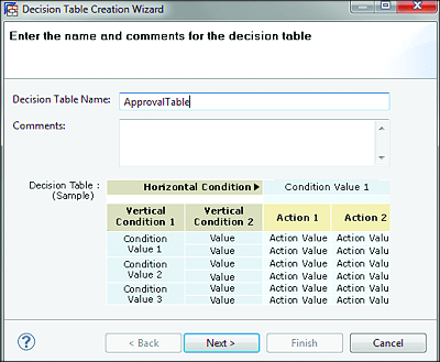
Enter “ApprovalTable” as the name of the decision table and click on Next (Figure 13.41).
Figure 13.41 Decision Table Creation Wizard
-
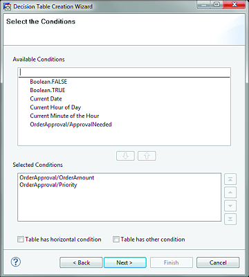
If everything worked properly in the previous steps, then you should see a window like the one shown in Figure 13.42. Use the small arrow buttons in the middle of the wizard window to move the entries OrderApproval/OrderAmount and OrderApproval/Priority from the Available Conditions to the Selected Conditions at the bottom of the screen. Click on Next.
Figure 13.42 Select Conditions for Decision Table
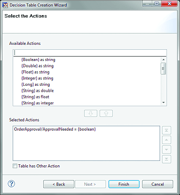
- Use the small arrow buttons in the middle of the wizard window to move the OrderApproval/ApprovalNeeded entry from the Available Actions to the Selected Actions at the bottom of the screen (the result is shown in Figure 13.43). Click on Finish.
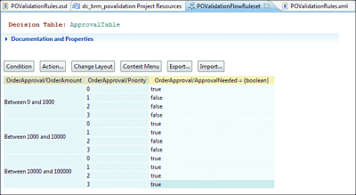
- You should now see the new decision table, as shown in Figure 13.44. Enter the values from Table 13.3 into the Condition and Action columns of the decision table. Save your work by pressing (Ctrl) + (S). When you finish, the final result should look like the one shown in Figure 13.45.
Figure 13.43 Select Actions for Decision Table
Figure 13.44 Decision Table with Default Values
Figure 13.45 Decision Table with Condition and Output Values
Configure Rule Flow
Now that you have the decision table in place, you can configure the rule flow part of your previously created flow ruleset (POValidationFlowRuleset), which will contain a graphical representation of the business rule as a flow. After that step, you’ll configure a test scenario to test the business rule with XML as input.
Select the POValidationFlowRuleset flow ruleset, and navigate to the Rule Flows tab. You should see the MainFlow rule flow with its default flow, as you saw previously (refer to Figure 13.39).
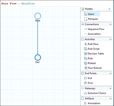
We’ll now model the flow with the aid of the objects from the Rules Composer Palette, which is on the right side of the screen when you open the rule flow (Figure 13.46).
Start modeling the rule flow by dragging and dropping the objects needed to achieve the flow (Figure 13.47). Press (Ctrl) + (S) to save your changes.
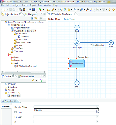
As you can see in Figure 13.47, there is a warning inside the decision table activity step in our flow because you still have to tell your rule flow which decision table it should use to execute this step. As you can imagine, at a certain point in a real project, there might be more than one decision table in the same rule flow.
You’ll now configure the decision table so that you can finish your rule flow. Select the Decision Table activity on the flow to open its Properties, and then select Browse from the Decision Table dropdown menu, as shown in Figure 13.47.
Figure 13.46 Rule Flow with Rules Composer Palette
Figure 13.47 Rule Flow with Warning
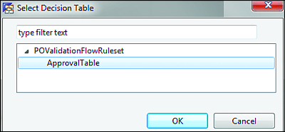
Select ApprovalTable and click on OK (Figure 13.48). Save your changes by pressing (Ctrl) + (S).
Figure 13.48 Decision Table Configuration in Rule Flow
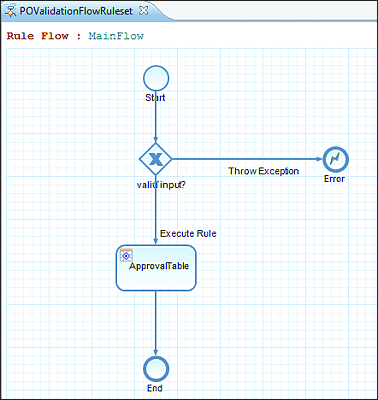
After you’ve configured the decision table, the rule flow should look like the one shown in Figure 13.49.
Figure 13.49 Rule Flow with Configured Decision Table
There is one last configuration step you have to perform before you can finish the rule flow. The gateway after the start step must be configured to check the input of the business rule. If the validation of the input fails, then the business rule will automatically trigger an exception with a standard error message. You can configure the error message by double-clicking on the error step and entering a text value.
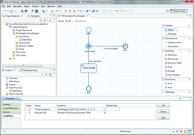
Configure the conditions inside the gateway activity by double-clicking on its symbol and opening its properties. Inside the gateway properties, click on the Conditions tab, and then click on the Edit button. Make sure that your gateway is configured as shown in Figure 13.50.
Figure 13.50 Gateway Activity for Input Validation
Table 13.4 shows the conditions as they must be configured for the gateway activity in your rule flow.
| Order | Name | Condition | Default Gate |
|---|---|---|---|
| 1 | Throw Exception | OrderApproval/Priority Not In 0 , 1 , 2 , 3 | |
| 2 | Execute Rule | Boolean.TRUE Equals Boolean.TRUE | X |
Table 13.4 Testing the Business Rule
Next, you’ll need to follow these steps:
-
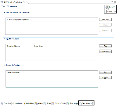
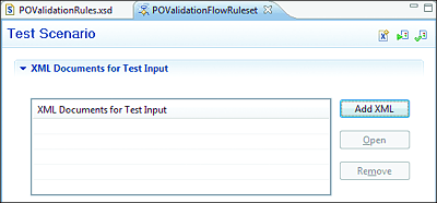
From the POValidationFlowRuleset flow ruleset, navigate to the Test Scenario tab. Click on the Add XML button (Figure 13.51).
Figure 13.51 Test Scenario Tab: Create XML
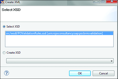
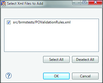
- Select POValidationRules.xsd, and click on OK (Figure 13.52).
-
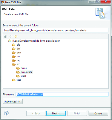
Enter “POvalidationRules.xml” as the name of the new XML file (Figure 13.53), and click on Next.
Figure 13.52 Test Scenario: Select XSD
Figure 13.53 Test Scenario: Create XML
-
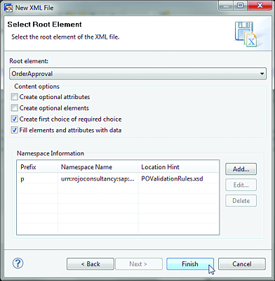
Accept the default values, and click on Finish (Figure 13.54).
Figure 13.54 Test Scenario: Select Root Element
-
Copy and paste the XML source code provided in Listing 13.3 into the XML Source tab. Press (Ctrl) + (S) to save your work.
<?xml version="1.0" encoding="UTF-8"?>
<p:OrderApproval xmlns:p="urn:rojoconsultancy:sap:po:brm:validation"
  xmlns:xsi="http://www.w3.org/2001/XMLSchema-instance">
  <OrderAmount>1001</OrderAmount>
  <Priority>3</Priority>
  <ApprovalNeeded>false</ApprovalNeeded>
</p:OrderApproval>
Listing 13.3 POValidationRules.xml
-
From the Test Scenario tab, click on the Add XML button, as shown in Figure 13.55.
Figure 13.55 Test Scenario: Add XML
- Select POValidationRules.xml, and click on OK (Figure 13.56).
Figure 13.56 Test Scenario: Select XML to Test
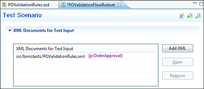
After the last step, your test scenario should now contain the XML (POValidationRules.xml) configured as input for the test. In Figure 13.57, you can see the test scenario configured with the input XML. Figure 13.58 also shows the contents of POValidationRules.xml.
Figure 13.57 Test Scenario: XML Input for Test Business Rule
Figure 13.58 Test Scenario: POValidationRules.xml
To support different test cases with the same XML file as input, you can change the values of the XML fields. Just make sure that the XML remains valid and that you save the XML after making any changes.
That’s it! You’re ready to run your test scenario and check whether your rule works according to the functional and technical requirements. From the Test Scenario tab, click on the Run Test Scenario button, as shown in Figure 13.59.
Figure 13.59 Test Scenario: Run Test Scenario
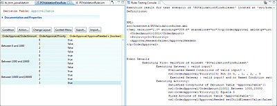
If everything worked correctly, you should see the results of the test in the Rules Testing Console, as shown in Figure 13.60.
Figure 13.60 Test Scenario: Rules Testing Console
Congratulations! You’ve officially created your first business rule in SAP PO.
