SAP Cloud Platform Integration
Since the introduction of cloud computing technology, there has been a shift in the level of investments by organizations in software licenses. Organizations are rapidly moving from the concept of software ownership to software rental. As a consequence, SAP is also currently growing its cloud portfolio with products for human resources (with SAP SuccessFactors), marketing, sales, service, procurement, supply chain management, and finance. We’re convinced that this portfolio will continue to grow.
You might now be wondering what SAP’s proposition is to integrate this armada of cloud applications. Part of the answer lies in SAP’s release and offering of SAP Cloud Platform Integration as its cloud-based integration platform-as-a-service (iPaaS) for enterprise and business-to-business (B2B) integration solutions.
SAP Cloud Platform Integration isn’t SAP Process Integration (SAP PI) on the cloud, but it’s a platform that supports full integration capabilities and combines certain functionalities of SAP PO and data services. It involves the creation of integration flows (iFlows) from an Eclipse-based development environment for end-to-end messaging and connectivity between on-premise and cloud solutions. It’s also possible to perform development activities from the web-based tool known as WebUI as an alternative to Eclipse.
This is an on-demand solution with prepackaged integration content and the possibility of enhancing this delivered content, and it can be integrated with other solutions. The cloud infrastructure is managed by SAP, with fixed pricing for services consumed by each customer.
Note that it’s not obligatory to run or use a hybrid scenario (on premise/on demand) in combination with SAP PO. You can decide to choose between SAP PO and SAP Cloud Platform Integration and only use one of them.
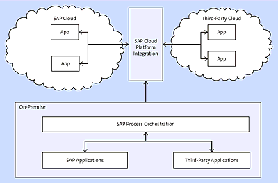
As Figure A.2 depicts, a typical organization that has adopted the cloud will have two different zones:
-
On premise
This zone includes the applications residing within the organization’s network boundaries. SAP PO can be used as the integration tool of choice for all exchange of messages happening within this zone. Furthermore, traffic through and between the cloud and on-premise applications could transit to your SAP PO system. Depending on circumstances and the scenario at hand, SAP Gateway can also be used.
Figure A.2 On-Premise to Cloud Integration with SAP Cloud Platform Integration and SAP PO
-
Cloud
This layer comprises your cloud ecosystem. This extension of your landscape, which resides outside the boundary of your organization, can be integrated using SAP Cloud Platform Integration. Then, you have a situation in which SAP Cloud Platform Integration on the cloud communicates with SAP PO on the on-premise side. SAP Cloud Platform Integration can also be used to enable cloud-to-cloud integration. In this situation, different SAP Cloud applications need to communicate with each other, or an SAP Cloud application needs to exchange messages with a third-party (non-SAP) cloud application.
The next sections of this book aren’t intended to tell all there is about SAP Cloud Platform Integration but to highlight some of the currently provided features of the SAP Cloud Platform Integration. For a full overview of SAP Cloud Platform Integration, refer to the book Getting Started with SAP HANA Cloud Integration by Bilay, Gutsche, Stiehl (SAP PRESS, 2016, www.sap-press.com/3979).
Features and Facts Overview of SAP Cloud Platform Integration
Security and performance issues are key reasons that people are skeptical of putting information on the cloud. SAP Cloud Platform Integration handles these concerns by supporting signing, encryption, and decryption of data that passes through the modeled flows from an end-to-end perspective.
SAP Cloud Platform Integration can be licensed in different forms and editions. We can distinguish between two main editions: the application and the standalone integration platform. This choice of package creates the flexibility for customers to choose the model that best fits their needs. The two options are as follows:
-
Application edition
This edition can be used by customers using other SAP cloud applications, such as SAP Cloud for Customer, SAP SuccessFactors, and SAP Financial Services Network (SAP FSN). This edition comes equipped with prepackaged content and flows that can directly be used without deep technical knowledge. This content can be found from the web-based application known as the Integration Content Catalog, which can be accessed via https://cloudintegration.hana.ondemand.com. -
Standalone integration platform edition
This is a version of SAP Cloud Platform Integration that enables you to integrate any application in your landscape (including SAP and third party). Within this context, we can distinguish two different levels: the SAP Cloud Platform Integration Standard and Professional packages. The standard edition is the entry-level package. It has the full integration capabilities but is limited in terms of the total amount of bandwidth that can be used per month. The professional package, on the other hand, caters for more bandwidth. The professional package has many more levels that customers can select from depending on their needs. It’s also important to mention the SAP Data Services Agent, which enables SAP’s customers to download the integration component.
SAP Cloud Platform Integration keeps adding new features on a regular basis, so check the SAP Cloud Platform Integration website to get more up-to-date details.
As it currently stands, the following features and facts apply to SAP Cloud Platform Integration:
- It has a multitenant architecture (separated firewall rules, separated system configuration, security, etc.).
- Availability of UI access to modify iFlows and prepackaged iFlows can also be downloaded to Eclipse and modified.
- All the functions of graphical mapping (in SAP PO) are supported; Extensible Stylesheet Language Transformations (XSLT) mapping can also be used.
- Existing SAP PO content is supported and can be imported into SAP Cloud Platform Integration (service interface, operation mapping, and message mapping objects).
- Connectivity options include IDoc, SOAP, and Secure FTP (SFTP) between backend systems. Additional connectivity options will become available in future releases.
- Certificates can also be browsed and supported on Eclipse-based environments.
- You can reuse user-defined functions (UDFs) defined in SAP PO.
- Two environments will be provided to SAP Cloud Platform Integration customers: development and production.
- SAP Cloud Platform Integration currently runs on top of Sybase as a database and not on SAP HANA’s in-memory database, but the future plan is to make it powered by SAP HANA.
- Software is upgraded every month on the SAP side for maintenance of the cloud infrastructure.
- The created iFlow can be deployed on the IFLMAP tenant node.
- Message monitoring functionalities are available on the server on which they are deployed, and the artifacts also are visible.
- SAP Cloud Platform Integration will run as an alternative to SAP PI, and small companies that don’t have the capacity can use it inexpensively.
- Partners and customers can create SAP Cloud Platform Integration solutions (reusable connectors and other integration logic) of their own and deploy them into the cloud. Additional Eclipse Software Development Kits (SDKs) will be provided for this purpose. These custom solutions can then be certified by SAP (this is planned for future releases in the roadmap).
- SAP Cloud Platform Integration provides a new opportunity for small, medium-sized, and large corporations to integrate their enterprise applications and integrate with partners at reduced costs and without investing heavily on software licenses.
Development Guide: Getting Started
This section describes the necessary steps for setting up the SAP Cloud Platform Integration environment.
SAP Cloud Platform Integration Workbench and Tools
This section describes the tools required to set up your SAP Cloud Platform Integration environment. The first tool necessary to have in place is Eclipse Kepler (a specific version of Eclipse). SAP Cloud Platform Integration uses Eclipse to contain the integrated development environment (IDE) and necessary perspectives that support SAP Cloud Platform Integration developments.
SAP Cloud Platform Integration Plug-Ins
You’ll need to install the appropriate SAP Cloud Platform Integration plugins into Eclipse to have the necessary artifacts for creating, designing, and monitoring iFlows. Follow these steps to add the plugins:
- From the main menu, choose Help • Install New Software.
- On the Available Software page of the Install wizard, add the update site URL https://tools.hana.ondemand.com/kepler.
-
Select from the among following three options:
- Show only the latest version of available software
- Groups items by category
- Contact all update sites during install to find required software
- Select the SAP Cloud Platform Integration Tools category.
- Click on Next.
- Check the features selected for installation, and click on Next.
- Accept the terms of the licensing agreement, and click on Finish.
- Restart the Eclipse IDE.
The Eclipse plug-in contains the following features:
-
Designer for SAP Cloud Platform Integration
This feature contains plugins to develop and configure iFlows. -
Operations for SAP Cloud Platform Integration
This feature contains plugins to perform administrative tasks related to SAP Cloud Platform Integration runtime clusters and to monitor iFlows. -
Certificates and security artifacts
Depending on the type of scenario in mind, designing and deploying iFlows on an SAP Cloud Platform Integration tenant requires you to take security aspects into consideration. Different types of security artifacts might need to be included. This could include Secure Sockets Layer (SSL; certificate authority, private key, and public key) and Secure Shell (SSH; private and public keys). Note that many CAs are currently supported (including SAP Passport CA), and more will be added as time goes by.
Because SAP Cloud Platform Integration currently supports the connectivity options (SOAP, IDoc, SAP Success Factors, and SFTP), the security artifacts previously listed can be used in most of them. -
Tenant account
A tenant account is needed to deploy your SAP Cloud Platform Integration developments. The details of the tenant include the tenant ID and the operations server. These details are needed to configure your Eclipse environment. For more information about how to apply for a tenant account, contact your SAP representative. The tenant will facilitate the execution of different integration operations, including the deployment of iFlows and the runtime monitoring of running flows.
Configuring Eclipse
When configuring Eclipse for your SAP Cloud Platform Integration environment, you’ll need to configure two different preference aspects in Eclipse: the operations server and the ES Repository. This section explains how to do so.
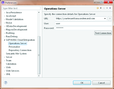
The operations server is required for deploying your SAP Cloud Platform Integration iFlows to the server. To set up the operations server, follow these steps:
- From your Eclipse IDE, navigate to Windows • Perspectives • SAP Cloud Platform Integration.
- From there, enter the necessary details to connect to the operations server, based on the tenant details (see Figure A.3).
- You can test the connection by using the Test Connection button. When successful, select the OK button.
Figure A.3 Setting Up the Operations Server in Eclipse
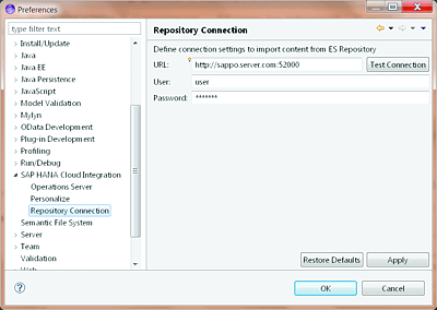
Repository Connection will normally point to the ES Repository. This configuration will enable the importing of SAP PI/SAP PO objects and artifacts, such as message mappings, operation mappings, and Web Service Description Language (WSDL) files. You’ll need to input the required details under the Repository Connection section (see Figure A.4).
Figure A.4 Configuring Details of the Repository Connection to Point to SAP PO’s ES Repository
Creating an Integration Flow
For simplicity’s sake, we’ll illustrate the usage of SAP Cloud Platform Integration by giving a high-level explanation of how to implement a simple SOAP-to-SOAP scenario. Follow these steps:
- Switch to the Integration Designer perspective by going to Window • Open Perspective. Choose Other and then Integration Designer.
- To create an iFlow, first create an integration project, click on the Project Explorer palette, and select New • Other.
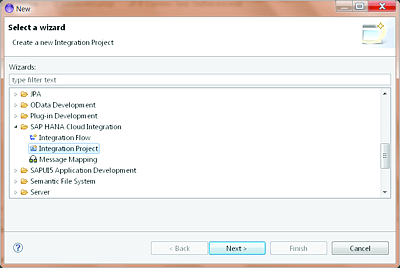
- Select Integration Project from the SAP Cloud Platform Integration folder (see Figure A.5).
- Click on Next, and name your iFlow.
-
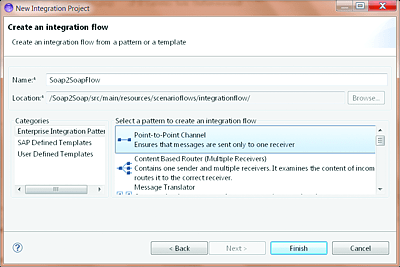
Proceed with the wizard, and provide some details about the iFlow to be created. Besides giving it a name, you’ll also need to specify a pattern to be used to create it. Each of the provided pattern templates contains an explanation of what it can be used for. For the sake of simplicity, choose Point-to-Point Channel (see Figure A.6).
Figure A.5 Creation of an iFlow
Figure A.6 Specifying Details of the iFlow and Its Pattern Template
- Click on the Finish button to complete the initial creation steps.
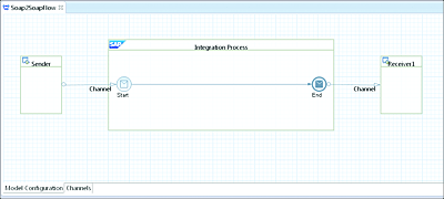
The resulting iFlow generated from the Point-to-Point Channel template looks like the image shown in Figure A.7.
Figure A.7 iFlow Based on the Point-to-Point Channel Pattern Template
Extend this empty iFlow and further configure it by following these steps:
- Configure the sender system, receiver system (name of the sender and receiver system; this is optional), and sender authorization (this is the public key pair).
- Import the WSDL file from SAP PI repository or local file system.
- Create a parameters file that contains attributes and metadata that can be referenced from the communication channels.
- Create a mapping between sender and receiver systems, or import existing mapping objects from the SAP PI repository.
- Create sender and receiver communication channels.
These steps will be explored in the next sections.
Configure Sender and Receiver Systems
To configure the sender and receiver systems, follow these steps:
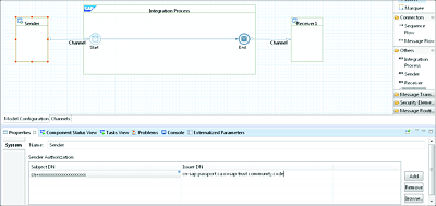
- From the iFlow just presented in Figure A.7, click on the sender system (on the left side of the diagram), check the property area, and enter an appropriate name for your sender system without whitespaces.
-
Under Sender Authorization, click on the Browse option to import your public SSL key (see Figure A.8). Adding the SSL key is required in the case of certificate-based authentication.
Figure A.8 Configure Sender System and Maintain Authorization
- Repeat the previous steps to configure the receiver system name. Note that there is no need to browse for the public key on the receiver side.
Import WSDL Files from SAP PI or Your Local File System
For the sake of simplicity, we’ll assume that you’ll reuse existing service interfaces from SAP PO for this scenario. You’ll then need to import them from your ES Repository. To import the service interfaces, follow these steps:
- Right-click on the name of the integration project in the explorer, choose the Import PI Content option, and choose the type of artifact to be imported. You’ll be asked to choose from among Message Mapping, Operation Mapping, and Interface. For our example, choose the Interface option. It will load the list of service interfaces for you to choose from. After selecting the desired service interface, click on the Finish button.
- Import the WSDL/service interface for the receiver system as well. These two service interfaces (for the sender and receiver) will be used during mapping. In addition, note that the WSDL file could also be imported from a local file system instead of the ES Repository. It’s mandatory to have SAP PI to use SAP Cloud Platform Integration.
Create a Parameters File
The parameters file contains the reference parameters to be used in your iFlow. Parameters can be created for a variety of attributes. A typical example includes the location of the WSDL file and the endpoint to be used during the configuration of the communication channels.
To create the parameters file, follow these steps:
- Right-click on the integration project, and choose New • Other. From the subsequent screen, select General and then File. Enter “parameters.prop” for the file name.
- Follow the wizard, and make sure that the newly created file is saved in the src.main.resources directory.
- Click on the Finish button.
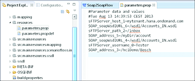
- Populate the newly created file with different parameters and their corresponding values (see Figure A.9 for an example configuration file).
Figure A.9 Parameters File
To reference these parameters during the configuration of a communication channel, the values on the right-hand side of the = sign are enclosed in double curly brackets—for example, {{SOAP_soapWsdlURL}}.
Mapping between Sender and Receiver System
Two possibilities exist to implement the mapping between the sender and receiver:
- Reuse an existing mapping. If you have an existing option that meets the requirement for passing data from the source system to the target system, then it can be imported from SAP PO using the same steps as for importing service interfaces.
- Create a new mapping from within the SAP Cloud Platform Integration Designer.
If you opt to create a new mapping, then follow these steps:
- Right-click on the integration project, and select New • Other. Under SAP Cloud Platform Integration, choose Message Mapping, and follow the wizard.
- Specify the name of the message mapping, and click on Finish.
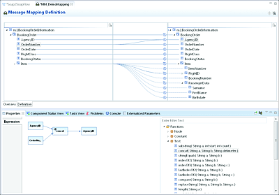
- The Overview screen of the newly created mapping opens. Choose the Definition tab to select the source and target structures to be used in your mapping.
-
Create a mapping between the source and target structures. The structure needs to be selected from the WSDL file imported earlier (an example is presented in Figure A.10).
Here, the mapping capability is similar to the one used in SAP BPM. It’s equipped with a number of predefined functions that can be used for defining the mapping logic. - Go back to the iFlow, and add a mapping artifact. This can be achieved by using the context menu on the horizontal line between the Start and End icons within the Integration Process box. Select the Add Mapping option. A new mapping artifact will be placed.
- Use the context menu on the newly added mapping artifact, and select the Assign Mapping option. On the resulting selection screen, select the previously created message mapping.
Figure A.10 Mapping Definition between Source and Target Structures
Sender and Receiver Communication Channels
The communication channels need to be configured to the desired adapter type. To configure a communication channel, follow these steps:
- Right-click on the channel artifact on the sender side. This is the horizontal line between the sender and the Integration Process box. Choose the Configure Channel option.
- The iFlow jumps into the Channels tab. From there, provide a name for the communication channel, and choose the desired adapter type. In this case, we’ll choose the SOAP adapter.
- You’ll also need to go to the Adapter Specific tab to specify further adapter details. The details to be specified include the endpoint and a link to a WSDL URL. The parameters defined in the parameters.prop file can be used here.
- You’ll need to perform the same configuration steps for the receiver communication channel.
The final configuration of the iFlow looks like the one presented in Figure A.11.
Figure A.11 Final Simple iFlow Configured in SAP Cloud Platform Integration
Deploying the Integration Project
After all the configurations are done, and all the changes saved, it’s time to deploy the iFlow to your SAP Cloud Platform Integration tenant. If a red marker appears on the integration project after saving, the configuration isn’t complete. Check the problem console to see more details about the error. To deploy the project to the cloud, follow these steps:
Right-click on the project, and choose the Deploy Integration Content option. A pop up is shown, asking for the tenant ID. After this is provided, the deployment will be performed.
Monitoring
After successfully deploying the iFlow to the SAP Cloud Platform Integration server, it’s time to monitor all running flows to make sure that they are correctly performing the jobs that they were built for and that they are helping the business achieve its goals.
This section will focus on looking at what’s required to properly monitor and track running flows in your tenant. Two main approaches can be used to monitor SAP Cloud Platform Integration flow:
- Via the Eclipse IDE
- Via the SAP Cloud Platform Integration tenant
The next sections will explore these two methods.
Monitor Using Eclipse
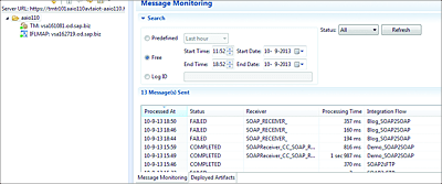
To monitor your flows directly from the Eclipse IDE, switch to the Integration Operation perspective. Figure A.12 shows the sample messages received by SAP Cloud Platform Integration. Further details and different search functionalities can be used from the monitoring tool.
Figure A.12 Message Monitoring from the Eclipse IDE
In the Message Monitoring screen, you can search messages based on different filtering criteria. The Message Monitoring screen shows different messages that have been received by the server. You can also see their statuses. Note that this perspective also makes a Deployed Artifacts tab available. As its name states, this tab lists all the artifacts that have been deployed to the SAP Cloud Platform Integration server, including iFlows.
Monitor Using WebUI
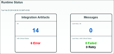
Monitoring processed messages is also possible using the SAP Cloud Platform Integration WebUI interface. WebUI can be accessed via http://<operations server url>/itspaces.
From this page, click on the Monitor link from the menu. You’ll land on a page that looks like the one shown in Figure A.13. This page presents a high-level overview of messages and artifacts with their statuses. You can click on the number to get more details of the objects in question.
Figure A.13 Runtime Status from WebUI
