Looking at the simplest of semiconductors, the lowly diode
Understanding how diodes can change AC to DC
Seeing how some diodes can make light
So far in this book, all the components I tell you about were invented in the first 100 years or so since Alessandro Volta invented the first electric battery in 1800. The next 50 years of electronics, from roughly 1900 to 1950, were dominated by a technology that’s now all but obsolete: vacuum tubes, which were large, expensive, fragile (they were made of glass), and required a lot of current.
In the 1940s, researchers developed a new technology that lead to new components that were, literally, a quantum-leap improvement over vacuum tubes. These new components were called semiconductors.
This chapter introduces you to the most basic kind of semiconductor, called a diode.
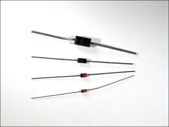
Diodes come in many shapes and sizes, but most of them resemble the ones shown in Figure 5-1
. These diodes are about the size of resistors and are available from any electronics supply store, such as RadioShack.
Although diodes look a little like resistors, they behave very differently. Diodes have one ability that sets them apart: They let current flow freely in one direction, but block current if it tries to flow in the other direction. In other words, a diode is like a turnstile gate that you can walk through in one direction but not the other. This characteristic turns out to be incredibly useful in electronic circuits.
I want to warn you from the outset that the first part of this chapter is fairly difficult, as it delves just a little into the physics of how semiconductors work at the atomic level. You don’t really have to understand the physics of diodes to use them in your circuits, so you can skip over the entire first section if you want, and start with the section “Introducing Diodes
,” later in this chapter. However, I recommend plowing through this first section no matter what. Don’t worry much if you have difficulty understanding how semiconductors work. Just take note of the key terms, such as p-type, n-type,
and p-n junction,
and move on.
What Is a Semiconductor?
As its name implies, a semiconductor
is a material that conducts current, but only partly. The conductivity of a semiconductor is somewhere between that of an insulator, which has almost no conductivity, and a conductor, which has almost full conductivity. Most semiconductors are crystals made of certain materials, most commonly silicon.
To understand how semiconductors work, you must first understand a little about how electrons are organized in an atom. The electrons in an atom are organized in layers, kind of like the layers of an onion. These layers are called shells.
The outermost shell is called the valence
shell. The electrons in this shell are the ones that
form bonds with neighboring atoms. Such bonds are called covalent bonds
because they share valence electrons, which are also the electrons that sometimes go wandering off in search of other atoms.
Most conductors, including copper and silver, have just one electron in the valence shell. Atoms with just one valence electron have a hard time keeping that electron. That’s what makes copper and silver such good conductors: When valence electrons travel, they create moving electric fields that push other electrons out of their way. That’s what causes current to flow.
Semiconductors, on the other hand, typically have four electrons in their valence shell. The best known elements with four valence electrons are carbon, silicon, and germanium. Atoms with four valence electrons rarely lose one of them. However, they do like to share them with neighboring atoms.
If all the neighboring atoms are of the same type, it’s possible for all the valence electrons to bind with valence electrons from other atoms. When that happens, the atoms arrange themselves into neat and orderly structures called crystals
. Semiconductors are made out of such crystals.
The most plentiful element with four valence electrons is carbon. However, carbon crystals are rarely used as semiconductors because they have other uses, such as in wedding rings. So instead, semiconductors are usually made from crystals of silicon and occasionally germanium.
Figure 5-2
shows the covalent bonds formed in a silicon crystal. Here, each circle represents a silicon atom, and the lines between the atoms represent the shared electrons. Each of the four valence electrons in each silicon atom is shared with one neighboring silicon atom. Thus, each silicon atom is bonded with four other silicon atoms.
FIGURE 5-2:
Silicon crystals are formed when each silicon atom shares its outermost electrons with a neighboring atom.
Doping: It’s not just for athletes
By themselves, pure silicon crystals are pretty, but not all that useful electronically. With all four valence electrons interlocked with neighboring atoms, it isn’t easy to get current to flow through a pure silicon crystal. But things get interesting if you introduce small amounts of other elements into a crystal. Then, the crystal starts to conduct in an interesting way.
The process of deliberately introducing other elements into a crystal is called doping.
The element introduced by doping is called a dopant.
By carefully controlling the doping process and the dopants that are used, silicon crystals can transform into one of two distinct types of conductors:
N-type semiconductor:
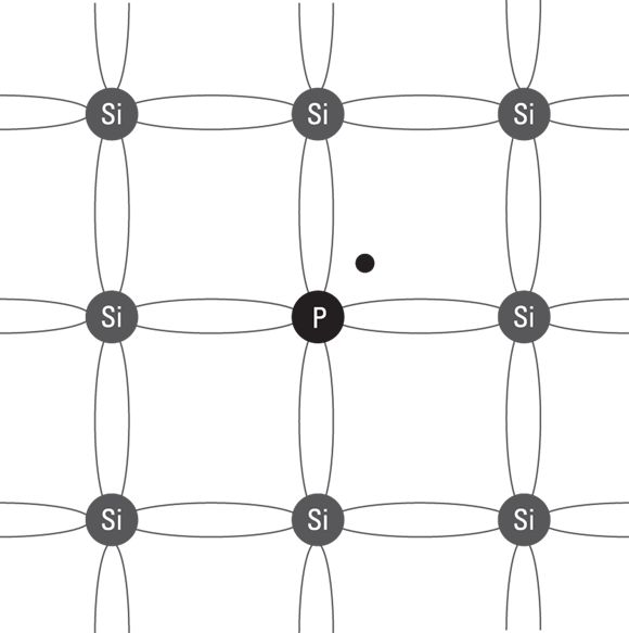
Created when the dopant is an element that has five electrons in its valence layer. Phosphorus is commonly used for this purpose. The phosphorus atoms join right in the crystal structure of the silicon, each one bonding with four adjacent silicon atoms just like a silicon atom would. Because the phosphorus atom has five electrons in its valence shell, but only four of them are bonded to adjacent atoms, the fifth valence electron is left hanging out with nothing to bond to.
The extra valence electrons in the phosphorous atoms start to behave like the single valence electrons in a regular conductor such as copper. They are free to move about, as shown in Figure 5-3
. Because this type of semiconductor has extra electrons, it’s called an N-type semiconductor.
P-type semiconductor:
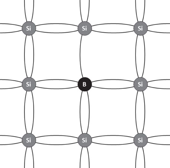
Happens when the dopant is an element (such as boron) that has only three electrons in the valence shell. When a small amount of boron is incorporated into the crystal, the boron atom is able to bond with four silicon atoms, but since it has only three electrons to offer, a gap is created where there would normally be an electron, as shown in Figure 5-4
. This electron gap is called a hole
. The hole behaves like a positive charge, so semiconductors doped in this way are called P-type semiconductors.
Like a positive charge, holes attract electrons. But when an electron moves into a hole, the electron leaves a new hole at its previous location. Thus, in a P-type semiconductor, holes are constantly moving around within the crystal as electrons constantly try to fill them up. A P-type semiconductor is like crazed pieces of Swiss cheese in which you can’t quite get a fix on the holes because they’re always moving.
FIGURE 5-3:
An N-type semiconductor has extra electrons.
FIGURE 5-4:
A P-type semiconductor has holes where electrons should be.
When voltage is applied to either an N-type or a P-type semiconductor, current flows, for the same reason that it flows in a regular conductor: The negative side of the voltage pushes electrons, and the positive side pulls them. The result is that the random electron and hole movement that’s always present in a semiconductor becomes organized in one direction, creating measurable electric current.
Understanding p-n junctions
By themselves, P-type and N-type semiconductors are just conductors. But if you put them together, an interesting and very useful thing happens: Current can flow through the resulting semiconductor, but only in one direction.
The p-n junction,
as it’s called,
is like a one-way gate. If you put positive voltage on the p side of the junction and negative voltage on the n side, current flows through the junction. But if you reverse the voltage, putting negative voltage on the p side and positive voltage on the n side, current doesn’t flow.
Picture a turnstile gate such as the gates you must go through to get into a baseball stadium or a subway station: You can walk through the gate in one direction but not the other. That’s essentially what a p-n junction does. It allows current to flow one way but not the other.
To understand why p-n junctions allow current to flow in only one direction, you must first understand what happens right at the boundary between the p-type material and the n-type material. Because opposite charges attract, the extra electrons on the n-type side of the junction are attracted to the holes on the p-type side. So they start to drift across to the other side.
When an electron leaves the n-type side to fill a hole in the p-type side, a hole is left in the n-type side where the electron was. Thus, it’s as if the electron and the hole trade places. The boundary of a p-n junction ends up being populated by defectors: Electrons and holes have crossed the boundary and are now on the wrong side of the junction.
This region that is occupied by electrons and holes that have crossed over is called the depletion zone.
Because one side of the depletion zone has electrons (negative charges) and the other side has holes (positive charges), a voltage exists between the two edges of the depletion zone. This voltage has an interesting effect on the defectors: It beckons them to turn around and come home. In other words, the holes that have jumped to the negative side of the junction attract the electrons that have jumped to the positive side.
Imagine what it’s like to be an electron that has jumped over the boundary and into the p-type side of the junction. Being negatively charged, you’re attracted to move farther into the p side by the positively charged holes you see ahead of you. But you’re also attracted by the positively charged holes that now lie behind you — the very same hole you traded places with now exerts a pull on you that discourages you from going any farther.
Unable to make up your mind, you decide to just stay put. That’s exactly what happens to the electrons and holes that have crossed over to the other side. The depletion zone becomes stable — a state that’s called equilibrium.
Now consider what happens when the equilibrium is disturbed by a voltage placed across the p-n junction. The effect depends on which direction the voltage is applied, as follows:
If you apply positive voltage to the p-type side and negative voltage to the n-type side, the depletion zone is pushed from both sides toward the center, making it smaller. Electrons in to the n-type side of the junction are pushed by the voltage toward the depletion zone and eventually collapse it completely. When that happens, the p-n junction becomes a conductor, and current flows.
When voltage is applied in the reverse direction, the depletion zone is pulled from both sides of the junction, and thus it expands. The larger it gets, the more of an insulator the p-n junction becomes. Thus, when voltage is applied in the reverse direction, current doesn’t flow through the junction.
Introducing Diodes
A diode
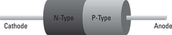
is a device made from a single p-n junction. As Figure 5-5
shows, leads are attached to the two ends of the p-n junction. These leads allow you to easily incorporate the diode into your circuits.
The lead attached to the n-type semiconductor is called the cathode.
Thus, the cathode is the negative side of the diode. The positive side of the diode — that is, the lead attached to the p-type semiconductor — is called the anode.
When a voltage source is connected to a diode such that the positive side of the voltage source is on the anode and the negative side is on the cathode, the diode becomes a conductor and allows current to flow. Voltage connected to the diode in this direction is called forward bias
.
But if you reverse the voltage direction, applying the positive side to the cathode and the negative side to the anode, current doesn’t flow. In effect, the diode becomes an insulator. Voltage connected to the diode in this direction is called reverse bias.
Forward bias allows current to flow through the diode. Reverse bias doesn’t allow current to flow. (Up to a point, anyway. As you discover in just a few moments, there are limits to how much reverse bias voltage a diode can hold at bay.)
The schematic symbol for a diode is shown in the margin. The anode is on the left, and the cathode is on the right. Here are two useful tricks for remembering which side of the symbol is the anode and which is the cathode:
Think of the anode side of the symbol as an arrow that indicates the direction of conventional current flow — from positive to negative. Thus, the diode allows current to flow in the direction of the arrow.
Think of the vertical line on the cathode side as a giant minus sign, indicating which side of the diode is negative for forward bias.
Figure 5-6
illustrates forward and reverse bias with two very simple circuits that connect a lamp to a battery with diodes. In the circuit on the left, the diode is forward biased, so current flows through the circuit and the lamp lights up. In the circuit on the right, the diode is reverse biased, so current doesn’t flow and the lamp remains dark.
FIGURE 5-6:
Forward and reverse bias on a rectifier diode.
Note that in a typical diode, a certain amount of forward voltage is required before any current will flow. This amount is usually very small. In most diodes, this voltage is around half a volt. Up to this voltage, current doesn’t flow. Once the forward voltage is reached, however, current flows easily through the diode.
This minimum threshold of voltage in the forward direction is called the diode’s forward voltage drop.
That’s because the circuit loses this voltage at the diode. For example, if you were to place a voltmeter across the leads of the diode in the
forward-biased circuit in Figure 5-6
(left), you would read the forward voltage drop of the diode. Then, if you were to place the voltmeter across the lamp terminals, the voltage would be the difference between the battery voltage (9 V) and the forward voltage drop of the diode.
For example, if the forward voltage drop of the diode was 0.7 V and the battery voltage was exactly 9 V, the voltage across the lamp would be 8.3 V.
Diodes also have a maximum reverse voltage they can withstand before they break down and allow current to flow backward through the diode. This reverse voltage (sometimes called PIV
, for peak inverse voltage,
or PRV
for peak reverse voltage
) is an important specification for diodes you use in your circuits, as you need to ensure that your diodes won’t be exposed to more than their PIV rating.
Besides the forward-voltage drop and peak inverse voltage, diodes are also rated for a maximum current rating. Exceed this current, and the diode will be damaged beyond repair.
The Many Types of Diodes
Diodes come in many different flavors. Some of them are exotic and rarely used by hobbyists, but many are commonly used. The following sections describe three types of diodes you’re likely to encounter in your electronic pursuits: rectifier, signal, and Zener diodes. Later in this chapter, you also learn about light-emitting diodes, or LEDs.
Rectifier diodes
A rectifier diode
is designed specifically for circuits that need to convert alternating current to direct current. The most common rectifier diodes are identified by the model numbers 1N4001 through 1N4007. These diodes can pass currents of up to 1 A, and they have peak inverse voltage (PIV) ratings that range from 50 to 1,000 V.
Table 5-1
lists the peak inverse voltages for each of these common diodes. When choosing one of these diodes for your circuit, pick one that has a PIV that’s at least double the voltage you expect it to be exposed to. For most battery-power circuits, the 50 V PIV of the 1N4001 is more than sufficient.
Most rectifier diodes have a forward voltage drop
of about 0.7 V. Thus, a minimum of 0.7 V is required for current to flow through the diode.
Signal diodes
A signal diode
is designed for much smaller current loads than a rectifier diode and can typically handle about 100 mA or 200 mA of current.
The most commonly used signal diode is the 1N4148. This diode has a close brother called 1N914 that can be used in its place if you can’t find a 1N4148. This diode has a forward-voltage drop of 0.7 and a peak inverse voltage of 100 V, and can carry a maximum of 200 mA of current.
Here are a few other interesting points to ponder about signal diodes:
They’re noticeably smaller than rectifier diodes and are often made of glass. You have to look at them closely to see it, but the cathode end of a signal diode is marked by a small black band.
They’re better than rectifier diodes when dealing with high-frequency signals, so they’re often used in circuits that process audio or radio frequency signals. Because of their ability to respond quickly at high frequencies, signal diodes are sometimes called high-speed diodes
. They’re also sometimes called switching diodes
because digital circuits (which you learn about in Book 5
) often use them as high-speed switches.
Some signal diodes are made of germanium rather than silicon. (Germanium the crystal, not to be confused with geranium the flower.) Germanium diodes have a much smaller forward-voltage drop than silicon diodes — as low as 0.15 V. This makes them useful for radio applications, which often deal with very weak signals.
Zener diodes
In a normal diode, the peak inverse voltage is usually pretty high — 50, 100, even 1,000 V. If the reverse voltage across the diode exceeds this number, current floods across the diode in the reverse direction in an avalanche, which usually results in the diode’s demise. Normal diodes aren’t designed to withstand a reverse avalanche of current. Zener diodes
are. They’re specially designed to withstand current that flows when the peak inverse voltage is reached or exceeded. And more than that, Zener diodes are designed so that as the reverse voltage applied to them exceeds the threshold voltage, current flows more and more in a way that holds the voltage drop across the diode at a fixed level. In other words, Zener diodes can be used to regulate the voltage across a circuit.
In a Zener diode, the peak inverse voltage is called the Zener voltage.
This voltage can be quite low — in the range of a few volts — or it can be hundreds of volts.
Zener diodes are often used in circuits where a predictable voltage is required. For example, suppose you have a circuit that will be damaged if you feed it with more than 5 V. In that case, you could place a 5 V Zener diode across the circuit, effectively limiting the circuit to 5 V. If more than 5 V is applied to the circuit, the Zener diode conducts the excess voltage away from the sensitive circuit.
Zener diodes have their own variation of the standard diode schematic symbol, as shown in the margin. You can learn more about working with Zener diodes in Book 4, Chapter 2
.
Using a Diode to Block Reverse Polarity
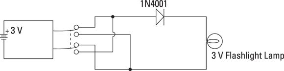
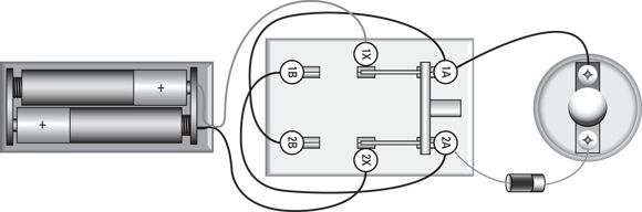
Project 15 presents a simple little construction project that demonstrates a diode’s ability to conduct current in only one direction. For this project, you wire up a rectifier diode in series with a 3 V flashlight lamp and a pair of AA batteries. I have you use a DPDT knife switch between the battery and the diode/lamp circuit so that when the switch is changed from one position to the other, the polarity of the voltage across the diode and lamp is reversed. Thus, the lamp lights in only one of the two switch positions. Figure 5-7
shows the completed project.
In this project, you build a simple circuit that uses a diode to allow current to flow through a lamp circuit in only one direction. The circuit uses a DPDT knife switch to reverse the polarity of the battery. When the polarity is reversed, the diode blocks the current so the lamp does not light up.
You need a small Phillips-head screwdriver, wire cutters, wire strippers, and a multimeter to complete this project.
Parts
Two AA batteries
One battery holder (RadioShack 2700408)
One lamp holder (RadioShack 2720357)
One 2.33 V flashlight lamp (RadioShack 2721175)
One DPDT knife switch (RadioShack 27501537)
One 1N4001 rectifier diode (RadioShack 2761101)
Three 5-inch 22-gauge stranded wires
Steps
Stripinch of insulation from each end of the wires.
Open the switch.
Move the handles to their upright positions so none of the contacts is connected.
Attach the red lead from the battery holder to terminal 1X of the switch.
Attach the black lead from the battery to terminal 2X of the switch.
Use one of the three 5-inch wires to connect terminal 1B of the switch to terminal 2A.
Use a second 5-inch wire to connect terminal 2B of the switch to terminal 1A.
Use the third 5-inch wire to connect terminal 1A of the switch to one terminal of the lamp socket.
Connect the diode to terminal 2A of the switch and the empty terminal of the lamp socket.
The cathode (the side with the stripe) should be connected to the lamp.
Insert the lamp into the lamp holder.
Insert the batteries into the battery holder.
The circuit is now ready to test.
Flip the switch to the B position.
The lamp lights because positive voltage is connected to the diode’s anode and negative voltage is applied to the cathode side of the circuit. This allows current to flow through the diode, and the lamp turns on.
Flip the switch to the A position.
This time, the lamp goes out because voltage is reversed across the diode.
Use your multimeter to measure the voltages across the battery, lamp, and diode.
Set the multimeter to a DC volts range that will accommodate the 3 V battery voltage. Then take the measurements indicated in Table 5-2
.
The third measurement (the voltage across the diode) should be very close to 0.7 V. The second measurement (the voltage across the lamp) plus the voltage across the diode should add up to the first measurement (the voltage across the battery).
Don’t worry if they’re slightly off — the difference may be accounted for by inaccuracies in your voltmeter, especially if you have an analog meter or a very inexpensive digital meter.
One of the most common uses for rectifier diodes is to convert household alternating current into direct current that can be used as an alternative to batteries. You learn all about creating complete power supplies for this purpose in Book 4, Chapter 2
. For now, just concentrate on one part of a complete DC power supply: the rectifier circuit, which is typically made from a set of cleverly interlocked diodes. (A rectifier
is a circuit that converts alternating current to direct current.)
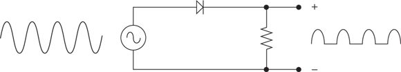
In household current, the voltage swings from positive to negative in cycles that repeat 60 times per second. If you place a diode in series with an alternating current voltage, you eliminate the negative side of the voltage cycle, so you end up with just positive voltage, as shown in Figure 5-8
.
FIGURE 5-8:
Using a diode to rectify alternating current.
If you look at the waveform of the voltage coming out of this rectifier diode, you’ll see that it consists of intervals that alternate between a short increase of voltage and periods of no voltage at all. This is a form of direct current because it consists entirely of positive voltage. However, it pulsates: First it’s on, then it’s off, then it’s on again, and so on.
Overall, voltage rectified by a single diode is off half of the time. So although the positive voltage reaches the same peak level as the input voltage, the average level of the rectified voltage is only half the level of the input voltage. This type of rectifier circuit is sometimes called a half-wave rectifier
because it passes along only half of the incoming alternating current waveform.
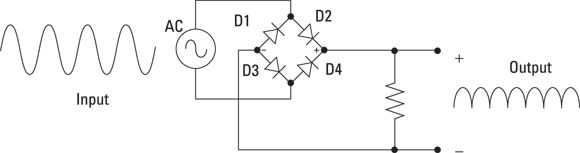
A better type of rectifier circuit uses four rectifier diodes, in a special circuit called a bridge rectifier.Figure 5-9
shows a bridge rectifier circuit.
Look at how this rectifier works on both sides of the alternating current input signal:
In the first half of the AC cycle, D2 and D4 conduct because they’re forward biased. Positive voltage is on the anode of D2 and negative voltage is on the cathode of D4. Thus, these two diodes work together to pass the first half of the signal through.
In the second half of the AC cycle, D1 and D3 conduct because they’re forward biased: Positive voltage is on the anode of D1, and negative voltage is on the cathode of D3.
The net effect of the bridge rectifier is that both halves of the AC sine wave are allowed to pass through, but the negative half of the wave is inverted so that it becomes positive.
The resulting DC signal doesn’t drop to zero for half of the cycle. However, it still doesn’t provide a steady DC voltage level. Think about what you learn in Chapters 3
and 4
of this minibook, though. Both capacitors and inductors can be used to slow down changes in current and voltage. Thus, capacitors and inductors are often used in power supply circuits to improve the quality of DC voltage coming out of a rectifier circuit. You can learn more about how that’s done in Book 4, Chapter 2
. But first, let’s look at rectifiers in action.
Building Rectifier Circuits
In Project 16, you build simple half-wave and bridge rectifier circuits to see how diodes can convert alternating current to direct current. You don’t light any lamps or anything with this circuit; instead, just use a voltmeter to verify that the diodes are doing their job. And to keep things safe, use a 9 V AC power adapter as the source for the alternating current. You should be able to find a 9 V AC power adapter for about $15 online, or you may find one for a dollar or two at a thrift store.
To make the voltage of the 9 V AC power adapter easier to work with, I suggest you cut off the power plug, separate the two wire leads, strip a bit of insulation from the ends, and attach alligator clips to the leads. The alligator clips make it much easier to connect the supply to your experimental circuits.
Before you build the project, use the multimeter to measure the AC voltage actually created by your power adapter. Although it may be marked as 9 V AC, the actual voltage you measure may be slightly more than 9 V AC.
You can find more information about rectifiers and how they’re used in power supply circuits in Book 4, Chapter 2
. For the remainder of this chapter, turn your attention to another useful type of diode: the light-emitting kind.
Project 16: Rectifier Circuits
In this project, you build a simple half-wave rectifier and a bridge rectifier. You connect the rectifiers to a 9 V AC power source, then use your multimeter to measure the DC output voltage to verify that the AC voltage has been converted to DC.
Parts
One 9 V AC power adapter
Two alligator leads (with alligator clips on both ends)
One small solderless breadboard
Four 1N4001 rectifier diodes (RadioShack 2761101)
One multimeter with AC and DC voltmeter functions
Steps
Start by building a simple half-wave rectifier:
Insert one of the diodes in the solderless breadboard.
Insert the anode in hole B10 and the cathode in hole B15. (The cathode is the lead that has the stripe next to it.)
Set the multimeter to a suitable V DC range.
10 V DC or 20 V DC should be fine.
Connect one lead of the power adapter to the anode.
The anode is the lead inserted into hole B10.
Connect the other lead of the power adapter to the black multimeter probe.
Use an alligator clip.
Plug the power adapter into a wall outlet.
When the power adapter is plugged in, be careful to prevent the two leads of the power adapter from coming into contact with one another. The resulting short circuit could damage the power adapter.
Touch the red multimeter probe to the diode cathode to measure the DC voltage rectified by the diode.
Note that the DC voltage is about half of the input AC voltage. That’s because the single diode is allowing only half of the AC sine wave to pass.
Unplug the power adapter.
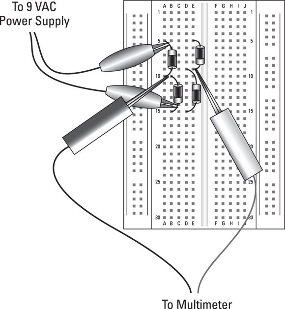
That’s it for the half-wave rectifier. Now build the bridge rectifier.
Insert the three remaining diodes to complete the bridge rectifier.
When you’re done, the four diodes should be inserted into the following holes.
Cathode (Striped End)
Anode
B15
B10
A5
A10
E9
E5
D9
D15
It’s important to note that the first two diodes share a common lead in row 10, while the second two diodes share a common lead in row 9. Make sure you don’t insert all four of these diodes into the same row. If you do, the bridge rectifier circuit won’t work.
Connect one lead of the AC power adapter to the diode lead in hole A5.
Connect the other lead of the AC power adapter to the diode lead in hole B15.
Plug in the 9 V AC power adapter.
Measure the voltage across the bridge rectifier.
Touch the black multimeter probe to the diode lead in hole A10 and the red probe to the diode lead in hole E9.
Be careful not to accidentally short out any of the leads when you touch them with the voltmeter probes.
Introducing Light Emitting Diodes
A light-emitting diode
(also called an LED
) is a special type of diode that emits visible light when current passes through it. The most common type of LED emits red light, but LEDs that emit blue, green, yellow, or white light are also available.
The word LED
is pronounced by spelling the letters out (el-ee-dee),
not like the word lead.
The schematic diagram symbol for an LED is shown in the margin, and Figure 5-10
shows typical LEDs. The two leads protruding from the bottom of an LED aren’t the same length: The shorter lead is the cathode, while the anode is the longer lead.
FIGURE 5-10:
LEDs. The shorter lead is the cathode.
Whenever you use an LED in a circuit, you must provide some resistance in series with the LED, as shown in the schematic diagram in Figure 5-11
. Otherwise, the LED will light brightly for an instant, and then burn itself out. In this example, the LED is connected to a 9 V DC supply through a
resistor.
FIGURE 5-11:
A resistor should always be used in series with an LED.
To determine the value of the resistor you should use, you need to know these three things:
The supply voltage:
For example, 9 V.
The LED forward-voltage drop:
For most red LEDs, the forward-voltage drop is 2 V. For other LED types, the voltage drop may be different. Check the specifications on the package if you use other types of LEDs.
The desired current through the LED:
Usually, the current flowing through the LED should be kept under 20 mA.
Once you know these three things, you can use Ohm’s law to calculate the desired resistance. The calculation requires just four steps, as follows:
Calculate the resistor voltage drop.
You do that by subtracting the voltage drop of the LED (typically 2 V) from the total supply voltage. For example, if the total supply voltage is 9 V and the LED drops 2 V, the voltage drop for the resistor is 7 V.
Convert the desired current to amperes.
In Ohm’s law, the current must be expressed in amperes. You can convert milliamperes to amperes by dividing the milliamperes by 1,000. Thus, if your desired current through the LED is 20 mA, you must use 0.02 in your Ohm’s law calculation.
Divide the resistor voltage drop by the current in amperes.
This gives you the desired resistance in ohms. For example, if the resistor voltage drop is 7 V and the desired current is 20 mA, you need a
resistor.
Round up to the nearest standard resistor value.
The next higher resistor value from
is
. If you can’t find a
resistor, a
will do the trick.
Note that the minor increases in resistances mean that slightly less current will flow through the resistor, but the difference won’t be noticeable. However, you should avoid going to a lower resistor value. Lowering the resistance increases the current, which can damage the LED.
Here are a few additional things to remember when you work with LEDs:
If you’re going to place more than one LED together in series, just add up the voltage drops to calculate the size of the resistor you need. For example, if you have a 9 V battery that will supply voltage to three LEDs, each with a 2 V drop, the total voltage drop is 6 V, so the voltage drop across the resistor is 3 V. Using Ohm’s law, you can then calculate that the resistor needed to restrict the current flow to 20 mA is
.
For 9 V and less,
resistors are more than adequate. If you’re applying larger voltages to the LED circuit, you may need to use resistors that can handle more power. To calculate how much power in watts the resistor should be rated for, just multiply the voltage dropped across the resistor by the current in amps. For example, if the voltage drop on the resistor is 3 V and the current is 20 mA, the power dissipated by the resistor will be 0.06 W, which is well under the limits of a
resistor.
You can get two LEDs, usually of different colors, combined into a single package. Green and red are a common combination. When two LEDs are bundled in a single package, they’re usually wired opposite of one another. That way, you can control which LED lights by changing the polarity of the voltage applied across the LED. In some cases, a third lead is used. This lead is connected to the cathode of both LEDs. The third lead enables you to light both LEDs, which yields a third color. For example, when both LEDs are lit in a green and red combination LED, the resulting color is yellow.
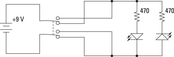
Using LEDs to Detect Polarity
In this section, you build a project that uses two LEDs to indicate the polarity of an input voltage. The voltage is provided by a 9 V battery connected to the circuit via a DPDT knife switch that’s wired to reverse the battery polarity. The two LEDs and their corresponding resistors are mounted on a small solderless breadboard. Figure 5-12
shows the completed circuit.
In this project, you build a polarity detector that uses LEDs to indicate the polarity of a power supply.
You need a small Phillips-head screwdriver, wire cutters, and wire strippers to assemble the circuit.
Parts
One 9 V battery
One 9 V snap-on battery holder (RadioShack 2700325)
One DPDT knife switch (RadioShack 2751537)
Two red LEDs, 5mm (RadioShack 2760209)
Two
resistors
Two short (less than 1-inch) jumper wires
Four 5-inch 22-gauge stranded wires
Steps
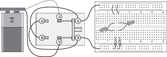
Throughout these steps, use the negative (–) bus strip on the bottom side of the board for ground and the positive (+) bus strip on the top of the board as the positive voltage.
Stripinch of insulation from each end of the wires.
Open the switch.
Move the handles to their upright positions so none of the contacts is connected.
Attach the red lead from the battery holder to terminal 1X of the switch.
Attach the black lead from the battery to terminal 2X of the switch.
Use a 5-inch wire to connect terminal 1B of switch to terminal 2A.
Use a 5-inch wire to connect terminal 2B of switch to terminal 1A.
Use a 5-inch wire to connect terminal 1A of the switch to any hole on the positive breadboard bus.
Use a 5-inch wire to connect terminal 2A of the switch to any hole on the negative breadboard bus.
Use a short jumper wire to connect hole J8 on the breadboard to any nearby hole on the positive bus strip.
Use a short jumper wire to connect hole A10 to any nearby hole on the positive bus strip.
Insert one of the resistors in hole B8 and any nearby hole on the negative bus strip.
Insert the other resistor in hole B10 and any nearby hole in the negative bus strip.
Connect the two LEDs on the breadboard as follows:
Cathode (short lead)
Anode (long lead)
Hole E8
Hole F8
Hole F10
Hole E10
Note that the cathode is the short lead.
Insert the 9 V battery into the battery holder.
Flip the switch to the A position.
The LED in row 8 lights up because the voltage from the battery is forward biased on this LED.
Flip the switch to the B position.
The LED in row 8 goes dark, but the one in row 10 lights up. This is because flipping the knife switch reverses polarity across the diodes.
 Digging deep into how semiconductors work
 I want to warn you from the outset that the first part of this chapter is fairly difficult, as it delves just a little into the physics of how semiconductors work at the atomic level. You don’t really have to understand the physics of diodes to use them in your circuits, so you can skip over the entire first section if you want, and start with the section “Introducing Diodes
,” later in this chapter. However, I recommend plowing through this first section no matter what. Don’t worry much if you have difficulty understanding how semiconductors work. Just take note of the key terms, such as p-type, n-type,
and p-n junction,
and move on.
I want to warn you from the outset that the first part of this chapter is fairly difficult, as it delves just a little into the physics of how semiconductors work at the atomic level. You don’t really have to understand the physics of diodes to use them in your circuits, so you can skip over the entire first section if you want, and start with the section “Introducing Diodes
,” later in this chapter. However, I recommend plowing through this first section no matter what. Don’t worry much if you have difficulty understanding how semiconductors work. Just take note of the key terms, such as p-type, n-type,
and p-n junction,
and move on.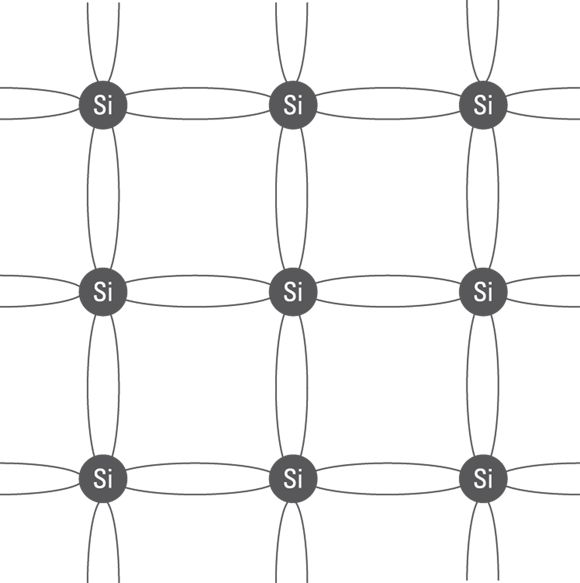
 Forward bias allows current to flow through the diode. Reverse bias doesn’t allow current to flow. (Up to a point, anyway. As you discover in just a few moments, there are limits to how much reverse bias voltage a diode can hold at bay.)
 The schematic symbol for a diode is shown in the margin. The anode is on the left, and the cathode is on the right. Here are two useful tricks for remembering which side of the symbol is the anode and which is the cathode:
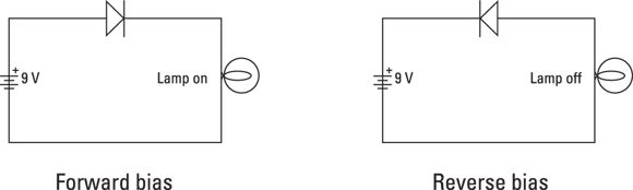
 Zener diodes have their own variation of the standard diode schematic symbol, as shown in the margin. You can learn more about working with Zener diodes in Book 4,
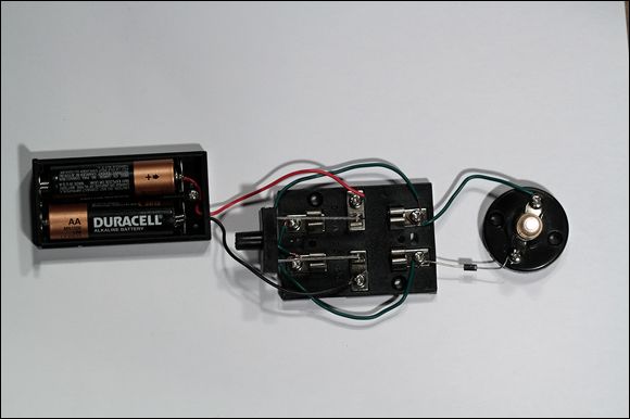
 inch of insulation from each end of the wires.
 The resulting DC signal doesn’t drop to zero for half of the cycle. However, it still doesn’t provide a steady DC voltage level. Think about what you learn in
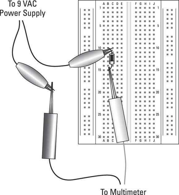
 The schematic diagram symbol for an LED is shown in the margin, and
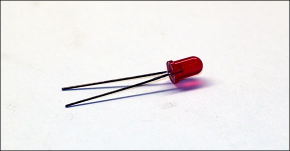
 Whenever you use an LED in a circuit, you must provide some resistance in series with the LED, as shown in the schematic diagram in
  resistor.
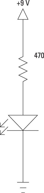
 resistor.
 is
is  . If you can’t find a
  resistor, a
  will do the trick.
 .
. resistors are more than adequate. If you’re applying larger voltages to the LED circuit, you may need to use resistors that can handle more power. To calculate how much power in watts the resistor should be rated for, just multiply the voltage dropped across the resistor by the current in amps. For example, if the voltage drop on the resistor is 3 V and the current is 20 mA, the power dissipated by the resistor will be 0.06 W, which is well under the limits of a
  resistor.
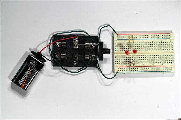
 resistors
 inch of insulation from each end of the wires.