Did you ever play Operation, the game in which you had to use electrified tweezers to remove plastic body parts from little holes in a body? The edges of the holes were metal conductors, so if you touched the edge of the hole with the tweezers while trying to remove the plastic piece inside, a buzzer would sound, and the patient’s nose (which was a red light bulb) would light up.
I was never very good at it, because it required nerves of steel and precise control of the tweezers. The slightest jiggle of the tweezers was amplified into a flashing light, a loud buzzer, and the mocking laughter of my brother, who was a much better Operation surgeon than I was.
An operational amplifier (op-amp for short) is kind of like the game Operation. Well, actually, it isn’t really, except for the part about the slightest variations in the input (your hand holding the tweezers) being amplified into a huge variation in the output (the flashing red nose, the jarring buzzer, and the ridicule of your brother).
Op-amps are among the most common types of integrated circuits — probably second in popularity only to the 555 timer chip, described in the previous chapter. In this chapter, you learn what an op-amp is and how to build several useful circuits with it. So put on your scrubs, and let’s start the operation!
Looking at Operational Amplifiers
An op-amp
is a super-sensitive amplifier circuit that’s designed to amplify the difference of two input voltages. Thus, an op-amp has two inputs and one output. The output voltage is often tens or even hundreds of thousands of times greater than the difference in the input voltages. Thus, a very small difference in the two input voltages — perhaps a few hundredths or even a few thousandths of a volt — can result in a large output voltage.
Although an op-amp is a type of integrated circuit, op-amps were invented long before integrated circuits. Op-amp circuits are a natural for integrated circuits, however, so it wasn’t long after the introduction of the first integrated circuits that IC versions of op-amps became available. Today, op-amps are among the most popular types of integrated circuits.
The name operational amplifier
may be a bit confusing. Originally, the op-amp circuit was created for use as an amplifier in telephone distribution systems. Later, computer engineers discovered that the circuit could easily be adapted to do mathematical operations such as addition, subtraction, multiplication, and division. It was around that time that the term operational amplifier
was coined, because the circuits are amplifiers that can perform (mathematical) operations. (For more information, see the nearby sidebar “How the op-amp came to be
.”)
Internally, the simplest op-amps consist of several dozen transistors, and more complicated varieties have many more. In this chapter, I completely ignore the internal circuitry of an op-amp and treat it as what it is: a handy device you can use without understanding how it works. You can thank the engineers who, many decades ago, worked out all the internal details that make an op-amp do its magic.
The standard schematic symbol for an op-amp is a triangle, as shown in Figure 3-1
. As you can see, the two inputs are on the left side of the triangle, the output is on the right, and the power supply connections for the circuit are on the top and bottom of the triangle.
Many types of op-amp chips are manufactured today, but all have the five connections shown in Figure 3-1
. The following paragraphs describe the function of each of these connections:
and:
The power supply for an op-amp is provided via two pins usually labeled
and
. (These pins may be labeled
and
instead, but their functions are the same.) Most op-amps require both a positive and a negative voltage power supply, with voltages usually ranging from
to
. This type of power supply is called a split supply.
The
indicates that both positive voltage and negative voltage are required.
, for example, means that both
and
are required.
You can easily build a split supply by using two batteries connected end to end, as shown in Figure 3-2
. Here, two 9 V batteries are connected to create a
supply. Note that the
and
are measured relative to ground, which is accessed between the two batteries.
Note that some op-amps don’t require split-voltage power supplies. Op-amps that use single power supplies have a ground terminal instead of a
terminal.
Vout
:
The output of the op-amp is taken from the Vout
terminal. The voltage at the output terminal can be positive or negative, depending on the voltage difference between the two input terminals. The maximum voltage is usually a few volts less than the supply voltage at the
and
terminals. Thus, if the power supply for an op-amp is
, the maximum output will be around
or 8 V.
Most op-amps can handle only a small amount of current through the output terminal — usually, in the neighborhood of 25 mA or less. As Figure 3-3
shows, the output is passed through an external resistance, designated RL
. The other end of this resistance is connected to ground. Thus, the output current that flows through the op-amp must eventually end up at ground.
Note that the load resistance isn’t necessarily in the form of a simple resistor; it can be any other circuit that provides some load resistance, such as the base-emitter circuit of a transistor or even input of another op-amp.
and:
The two inputs of an op-amp are the
and
terminals. These terminals are sometimes identified by + and – signs inside the triangle. The inputs are called differential inputs
because the output voltage, which appears on the Vout
terminal, depends on the difference between the voltage of the + and – terminals.
For most op-amps, the maximum allowable input voltage is a bit less than the maximum power supply voltage.
is a typical limit. Remember, though, that the difference
between the two input voltages is what an op-amp amplifies. In many cases, the two input voltages are very close, so the difference is very small.
I’ve said it already, but it’s worth repeating: The polarity of the op-amp output depends on the polarity of the difference between the
and
inputs. Thus, if
is greater than
, the output will be a positive voltage, but if
is less than
, the output will be a negative voltage.
In many op-amp circuits, one input is connected to ground. If the
input is grounded, the output polarity is always the opposite of the polarity of the input voltage on the
terminal. In other words, negative voltage on
will give positive voltage on Vout
, and positive voltage on
will give negative voltage on Vout
. For this reason, the
input is often called the inverting input
because its polarity is inverted in the output.
If, on the other hand, the
input is connected to ground, the polarity of the output is the same as the polarity of the input voltage applied to
. Thus, if
is positive, Vout
will be positive; if
is negative, Vout
will be negative. For this reason, the
input is called the noninverting input
because its polarity is the same in the output — that is, the
input voltage is not
inverted.
FIGURE 3-3:
The output from an op-amp passes to ground through a load resistance.
Understanding Open Loop-Amplifiers
As its name suggests, one of the most basic uses of an op-amp is as an amplifier. If you connect an input source to one of the input terminals and ground the other input terminal, an amplified version of the input signal appears on the out terminal.
An important concept in op-amp circuits is voltage gain,
which simply represents the amount by which the difference between the two input voltages is multiplied to produce the output voltage. If the input voltage difference is 2 V and the output voltage is 12 V, for example, the voltage gain of the amplifier is 6.
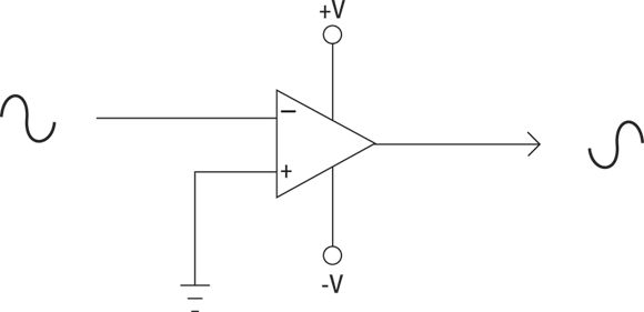
If you simply apply an input signal to the V–
terminal of an op-amp as shown in Figure 3-4
, the circuit is called an open loop-amplifier.
The reason it’s called this will become more apparent when you get to the next section. For now, just realize that this type of circuit goes by the name open loop.
FIGURE 3-4:
A op-amp configured as an open loop-amplifier.
In the open loop op-amp circuit, the
input is connected to ground, and an input signal is placed on the
input. In this arrangement, the voltage to be amplified is the same as the voltage of the
input. Although Figure 3-4
shows the input as alternating current, the open loop op-amp circuit works for direct current as well.
The voltage gain in an open loop op-amp circuit is extraordinarily high — on the order of tens or even hundreds of thousands. Suppose that you’re using an op-amp whose open loop voltage gain is 200,000 and that the power supply is
. In that case, an input voltage of
will result in an output voltage of
. An input voltage of
will give you an output voltage of 8 V.
The output voltage can never exceed the power supply voltage. In fact, the maximum output voltage usually is about 1 V less than the power supply voltage. So if you’re using a pair of 9 V batteries to provide a
power supply, the maximum output voltage is
. As a result, the most that an open loop op-amp circuit with an open loop gain of 200,000 can reliably amplify is 0.00004 V. If the input voltage difference is any larger than 0.00004 V, the op-amp is said to be saturated,
and the output voltage will go to the maximum.
I guarantee that no matter how much money you invested in a top-quality voltmeter, it isn’t sensitive enough to measure voltages that small. Physicists at Cal Tech may be able to measure voltages that size, but for all practical purposes, 0.00004 V is the same as 0 V.
As a result, one of the basic features of an open loop op-amp circuit is that if the input voltage difference is anything other than zero, the op-amp will be saturated, and the output voltage will be the same at its maximum. So if the maximum output voltage is
, the output will be one of only three voltages:
, 0 V, or
.
Open loop op-amp circuits may not sound very useful, but actually, they have many useful applications. You see one example in “Using an Op-amp as a Voltage Comparator
,” later in this chapter.
Looking at Closed Loop-Amplifiers
As I explain in the preceding section, open loop op-amp circuits aren’t very useful as amplifiers because they’re so easily saturated. To make an op-amp useful as an amplifier, you must use it in a feedback circuit,
which reduces the gain to a more manageable amount so that input voltages that are usable (and even measurable!) can be amplified reliably.
I’m sure that you’re already familiar with the concept of feedback. You’ve probably sat in an auditorium listening to someone talk into a public-address system when suddenly a piercing screech came out of the speakers. That screech was feedback. In the case of the public-address system, the microphone picked up some of the output from the speakers and sent it back through the amplifier again. The result was an annoying high-pitched squeal.
Not all feedback is bad, though. In an op-amp amplifier circuit, feedback is used to reduce the enormous open loop-amplification gain to a more manageable gain, such as 10. To do this, the output signal is fed back into the input via the
terminal. A resistor is used to reduce the voltage that is fed back to the input. This type of circuit is called a closed loop-amplifier
because a closed circuit path exists between the output and the input. (Now you understand why an op-amp circuit without the feedback loop is called an open loop-amplifier.
)
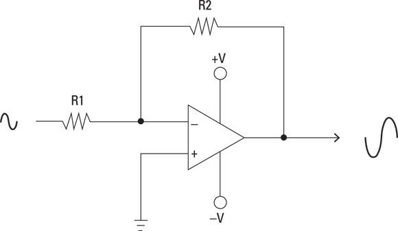
The most common op-amp configuration is called an inverting amplifier
because the voltage of the output is opposite the voltage of the input. Figure 3-5
shows a basic inverting amplifier circuit.
FIGURE 3-5:
An op-amp configured as an inverting amplifier.
In an inverting amplifier circuit, the input signal works its way through a resistor on its way to the
input, and the output is looped back into the
input through
a second resistor. In Figure 3-5
, these resistors are designated R1 and R2. You can easily calculate the overall voltage gain of the circuit by using this formula:
Here, the gain is designated ACL
(CL
stands for closed loop
).
If R1 is
and R2 is
, the voltage gain of the circuit will be
. Then if the input voltage is
, the output voltage will be
.
Note that the negative sign is required because Figure 3-5
is an inverting amplifier circuit, so positive inputs give negative outputs, and vice versa.
A closed loop-amplifier can also be designed as a noninverting amplifier
in which the output voltage is not reversed. To do that, you simply reverse the inputs, as shown in Figure 3-6
. Instead of connecting the input voltage to
through a resistor and grounding
, you ground
through a resistor and connect the input voltage to
. The feedback circuit is the same; the output is connected to the
input through resistor R1.
FIGURE 3-6:
An op-amp configured as a noninverting amplifier.
The formula for calculating the gain for a noninverting amplifier is a little different from the formula for an inverting amplifier:
If R1 is
and R2 is
, the gain is 11. Thus, an input voltage of
will result in an output voltage of
.
Using an Op-Amp as a Unity Gain Amplifier
A unity gain amplifier
is an amplifier circuit that doesn’t amplify. In other words, it has a gain of 1. The output voltage in a unity gain amplifier is the same as the input voltage.
You may think that such a circuit would be worthless. After all, isn’t a simple piece of wire a unity gain circuit? Sure, but a unity gain amplifier provides one important benefit: It doesn’t take any current from the input source. (Remember, that’s one of the Golden Rules of the ideal op-amp.) Therefore, it completely isolates the input side of the circuit from the output side of the circuit. Op-amps are often used as unity gain amplifiers to isolate stages of a circuit from one another.
Unity gain amplifiers come in two types: voltage followers and voltage inverters. A follower
is a circuit in which the output is exactly the same voltage as the input. An inverter
is a circuit in which the output is the same voltage level as the input but with the opposite polarity.
If you think about it for a moment, you might be able to come up with the circuit for unity gain followers and inverters on your own. The formula for calculating the gain of both an inverting amplifier and a noninverting amplifier requires you to divide R1 by R2, so all you have to do is choose resistor values that will result in a gain of 1.
The following sections explain how to create unity followers and unity inverters.
Configuring a unity follower
A unity gain follower is simply a noninverting amplifier with a gain of 1. Recall that the formula for calculating the value of a noninverting amplifier is this:
To create a unity gain follower, you just omit R2 and connect the output directly to the inverting input, as shown in Figure 3-7
. Because R2 is zero, the value of R1 doesn’t matter, because zero divided by anything equals zero. So R1 is usually omitted as well, and the
input isn’t connected to ground.
FIGURE 3-7:
An op-amp configured as a unity gain follower.
Configuring a unity inverter
The formula for calculating gain for an inverting amplifier is this:
In this case, all you have to do is use identical values for R1 and R2 to make the amplifier gain equal to 1. Figure 3-8
shows a unity gain inverter circuit using
resistors.
FIGURE 3-8:
An op-amp configured as a unity gain inverter.
Using an Op-Amp as a Voltage Comparator
A voltage comparator
is a circuit that compares two input voltages and lets you know which of the two is greater. Suppose that you have a photocell that generates 0.5 V when it’s exposed to full sunlight, and you want to use this photocell as a sensor to determine when it’s daylight. You can use a voltage comparator to compare the voltage from the photocell with a 0.5 V reference voltage to determine whether or not the sun is shining.
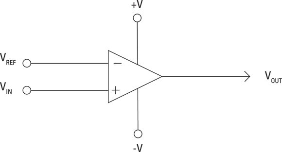
It’s easy to create a voltage comparator from an op-amp, because the polarity of the op-amp’s output circuit depends on the polarity of the difference between the two input voltages. Figure 3-9
shows the basic circuit for an op-amp voltage comparator.
FIGURE 3-9:
An op-amp configured as a voltage comparator.
In the voltage-comparator circuit, first a reference voltage is applied to the inverting input (
); then the voltage to be compared with the reference voltage is applied to the noninverting input. The output voltage depends on the value of the input voltage relative to the reference voltage, as follows:
Input Voltage
Output Voltage
Less than reference voltage
Negative
Equal to reference voltage
Zero
Greater than reference voltage
Positive
Note that the voltage level for both the positive and negative output voltages will be about 1 V less than the power supply. Thus, if the op-amp power supply is
, the output voltage will be
if the input voltage is greater than the reference voltage, 0 V if the input voltage is equal to the reference voltage, and
if the input voltage is less than the reference voltage.
You can modify the circuit to eliminate the negative voltage if the input is less than the reference by sending the output through a diode, as shown in Figure 3-10
. In this circuit, a positive voltage appears at the output if the input voltage is greater than the reference voltage; otherwise, no output voltage exists.
FIGURE 3-10:
Using a diode in a voltage-comparator circuit.
To create a voltage comparator that creates a positive voltage output if the input voltage is less than
a reference voltage, use the circuit shown in Figure 3-11
. Here, the input voltage is applied to the inverting (
) input, and the reference voltage is applied to the noninverting (
) input.
FIGURE 3-11:
A voltage comparator that tests for a voltage that’s less than a reference voltage.
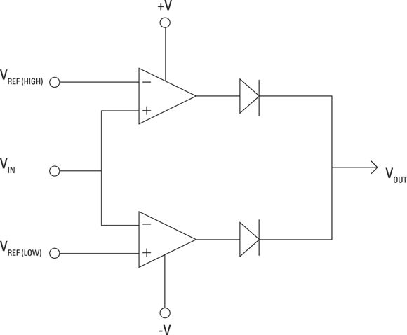
The final voltage-comparator circuit you should know about is the window comparator,
which lets you know whether the input voltage falls within a given range. A window comparator requires three inputs: a low reference voltage, a high reference voltage, and an input voltage. The output of the window comparator will be a positive voltage only if the input voltage is greater than the low reference voltage and less than the high reference voltage. If the input voltage is less than the low reference voltage, the output will be zero. Similarly, if the input voltage is greater than the high reference voltage, the output will also be zero.
You need two op-amps to create a window comparator, as shown in Figure 3-12
. As you can see in the figure, one op-amp is configured to produce positive output voltage only if the input is greater than the low reference voltage (VREF(LOW)
). The other op-amp is configured to produce positive output voltage only if the input is less than the high reference voltage (VREF(HIGH)
).
FIGURE 3-12:
Two op-amps can be used to create a window comparator.
The input voltage is connected to both op-amps; the output voltage is sent through diodes to allow only positive voltage and then combined. The resulting output will have positive voltage only if the input voltage falls between the low and high reference voltages.
Notice in Figure 3-12
that the power supply connections aren’t shown separately for each op-amp in the circuit. It’s common to omit the power supply connections when multiple op-amps are used in a single circuit. If the power supply connections were shown for all the op-amps, the power supply connections would complicate the schematic unnecessarily. I don’t know about you, but I don’t need any unnecessary complications in my life. I have enough necessary complications as it is.
Adding Voltages
An op-amp can be used to add or subtract two or more voltages. A circuit that adds voltages is called a summing amplifier.
A summing amplifier has two inputs and an output whose voltage is the sum of the two input voltages but with the opposite polarity. If one of the inputs is
and the other is
, for example, the output voltage will be
.
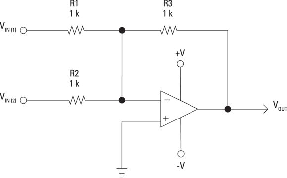
Figure 3-13
shows a basic circuit for a summing amplifier. For the summing amplifier to work, resistors R1, R2, and R3 should all be the same value.
If all the resistors in a summing amplifier are the same, the output voltage will be the sum of the input voltages. This is the usual way to configure a summing amplifier, though you can vary the resistor values if you want.
If the resistors have different values, each of the input voltages is weighted according to the value of the resistor on its input circuit, which has the effect of multiplying each input voltage by a certain value before the voltages are summed. The exact value by which each input is multiplied depends on the mix of resistors you use.
If R1 is
and R2 is
, for example, the input voltage applied through the
resistor will be multiplied by 10 before being added to the voltage applied through the
resistor. Thus, if the input at R1 is
, and the input at R2 is
, the output voltage will be
. (For this formula to work, R3 must also be
.)
The actual formula for calculating the output voltage based on the input voltages and the resistor values is this:
I’ll leave it to you to work out the math for various combinations of resistor values and input voltages. Here, though, are a few examples that should give you an idea of how the circuit will behave when R1 is
and both R2 and R3 are
:
VIN (1)
VIN (2)
VOUT
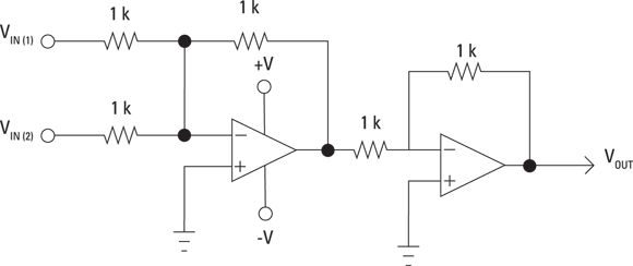
One drawback of the summing amplifier is that it inverts the polarity of the input, but you can easily feed the output of a summing amplifier into the input of a unity gain inverter, as shown in Figure 3-14
. Here, the second op-amp inverts the polarity of the output from the summing amplifier, which has the effect of returning the output voltage polarity to the polarity of the original inputs. (For more information about the voltage-inverter portion of this circuit, refer to “Using an Op-Amp as a Unity Gain Amplifier
,” earlier in this chapter.)
FIGURE 3-14:
A summing amplifier can be combined with a voltage inverter to preserve the input polarity.
One common use for a summing amplifier circuit is as an audio mixer. When this type of circuit is used as an audio mixer, each input is connected to a microphone. The summing amplifier combines all the microphone inputs by adding the voltages from each microphone, and the resulting output is sent on to another amplifier stage.
The resistors in each input circuit are often potentiometers, which allows you to vary the signal level from each input source. When you increase the resistance on one of the input circuits, less of that input is represented in the output mix — especially useful if one of your singers is a bit off key.
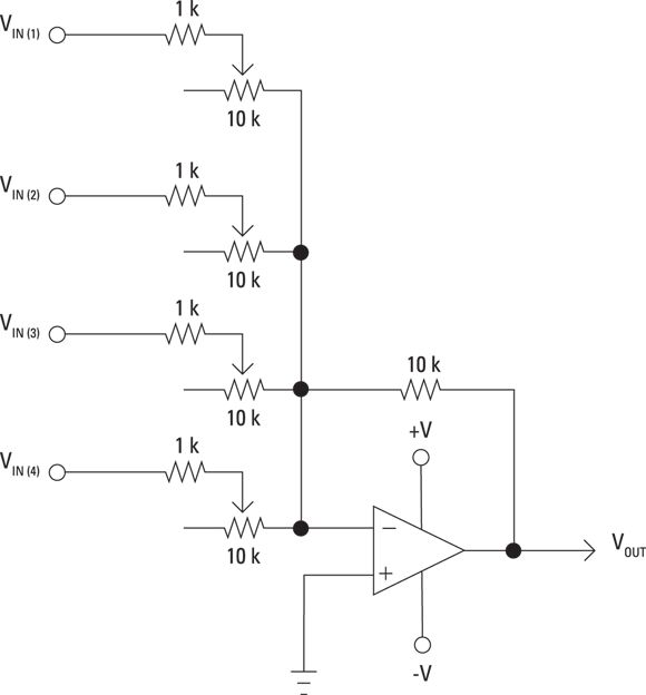
A summing amplifier circuit can be extended with additional inputs. Figure 3-15
shows a circuit with four inputs that uses potentiometers to control the level of each input. You can add as many inputs as you want, but you need to ensure that the total combined voltage from all inputs doesn’t exceed the power supply voltage (minus a volt or two).
FIGURE 3-15:
A simple audio mixer with four inputs.
One final variation of the summing amplifier circuit is used in conjunction with a second op-amp configured as an inverter. This configuration preserves the polarity of the input voltages.
Working with Op-Amp ICs
So far, all the examples in this chapter have assumed that you’re using a generic op-amp in your circuits. When you get around to building an actual op-amp circuit, of course, you’ll need to use a real op-amp. Fortunately, op-amp integrated circuits are plentiful, and nearly all stores that sell electronic components sell several types of inexpensive op-amp ICs.
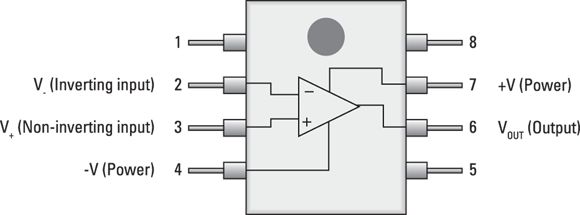
The most popular op-amp IC is the LM741, which comes in a standard eight-pin DIP package. Figure 3-16
shows the pin connections for an LM741 op-amp.
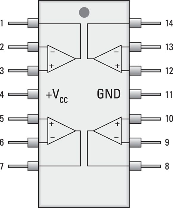
You can also get integrated circuits that contain two or more op-amps in a single package. One of the most common is the LM324 quad op-amp, which contains four op-amps in a single 14-pin DIP package. Unlike the LM741, the LM324 uses single power supply op-amps. Thus, instead of a split + and – voltage supply, you provide just a positive voltage power supply and a ground.
Figure 3-17
shows the pinouts for an LM324. As you can see, the first op-amp is accessed via pins 1–3, the second via pins 5–7, the third via pins 8–10, and the fourth via pins 12–14. The positive voltage power supply is connected to pin 4, and pin 11 is connected to ground.
 Getting familiar with op-amps
 The name operational amplifier
may be a bit confusing. Originally, the op-amp circuit was created for use as an amplifier in telephone distribution systems. Later, computer engineers discovered that the circuit could easily be adapted to do mathematical operations such as addition, subtraction, multiplication, and division. It was around that time that the term operational amplifier
was coined, because the circuits are amplifiers that can perform (mathematical) operations. (For more information, see the nearby sidebar “
The name operational amplifier
may be a bit confusing. Originally, the op-amp circuit was created for use as an amplifier in telephone distribution systems. Later, computer engineers discovered that the circuit could easily be adapted to do mathematical operations such as addition, subtraction, multiplication, and division. It was around that time that the term operational amplifier
was coined, because the circuits are amplifiers that can perform (mathematical) operations. (For more information, see the nearby sidebar “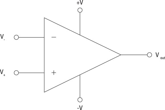
 and
and
 :
The power supply for an op-amp is provided via two pins usually labeled
:
The power supply for an op-amp is provided via two pins usually labeled  and
and  . (These pins may be labeled
  and
and  instead, but their functions are the same.) Most op-amps require both a positive and a negative voltage power supply, with voltages usually ranging from
  to
to  . This type of power supply is called a split supply.
The
. This type of power supply is called a split supply.
The  indicates that both positive voltage and negative voltage are required.
  , for example, means that both
  and
and  are required.
 supply. Note that the
  and
and  are measured relative to ground, which is accessed between the two batteries.
 terminal.
 and
and  terminals. Thus, if the power supply for an op-amp is
  , the maximum output will be around
  or 8 V.
 and
and
 :
The two inputs of an op-amp are the
:
The two inputs of an op-amp are the  and
and  terminals. These terminals are sometimes identified by + and – signs inside the triangle. The inputs are called differential inputs
because the output voltage, which appears on the Vout
terminal, depends on the difference between the voltage of the + and – terminals.
terminals. These terminals are sometimes identified by + and – signs inside the triangle. The inputs are called differential inputs
because the output voltage, which appears on the Vout
terminal, depends on the difference between the voltage of the + and – terminals. is a typical limit. Remember, though, that the difference
between the two input voltages is what an op-amp amplifies. In many cases, the two input voltages are very close, so the difference is very small.
is a typical limit. Remember, though, that the difference
between the two input voltages is what an op-amp amplifies. In many cases, the two input voltages are very close, so the difference is very small. and
and  inputs. Thus, if
  is greater than
  , the output will be a positive voltage, but if
  is less than
  , the output will be a negative voltage.
 input is grounded, the output polarity is always the opposite of the polarity of the input voltage on the
  terminal. In other words, negative voltage on
  will give positive voltage on Vout
, and positive voltage on
will give positive voltage on Vout
, and positive voltage on  will give negative voltage on Vout
. For this reason, the
will give negative voltage on Vout
. For this reason, the  input is often called the inverting input
because its polarity is inverted in the output.
input is often called the inverting input
because its polarity is inverted in the output. input is connected to ground, the polarity of the output is the same as the polarity of the input voltage applied to
  . Thus, if
  is positive, Vout
will be positive; if
is positive, Vout
will be positive; if  is negative, Vout
will be negative. For this reason, the
is negative, Vout
will be negative. For this reason, the  input is called the noninverting input
because its polarity is the same in the output — that is, the
input is called the noninverting input
because its polarity is the same in the output — that is, the  input voltage is not
inverted.
input voltage is not
inverted.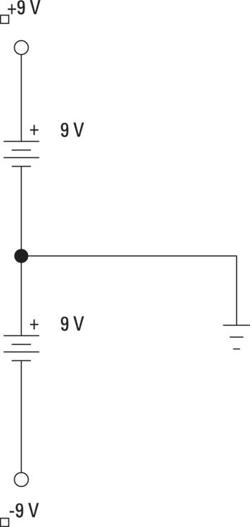
 supply for an op-amp.
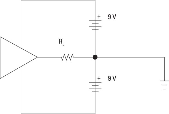
 input is connected to ground, and an input signal is placed on the
  input. In this arrangement, the voltage to be amplified is the same as the voltage of the
  input. Although
  . In that case, an input voltage of
  will result in an output voltage of
  . An input voltage of
  will give you an output voltage of 8 V.
 The output voltage can never exceed the power supply voltage. In fact, the maximum output voltage usually is about 1 V less than the power supply voltage. So if you’re using a pair of 9 V batteries to provide a
  power supply, the maximum output voltage is
  . As a result, the most that an open loop op-amp circuit with an open loop gain of 200,000 can reliably amplify is 0.00004 V. If the input voltage difference is any larger than 0.00004 V, the op-amp is said to be saturated,
and the output voltage will go to the maximum.
. As a result, the most that an open loop op-amp circuit with an open loop gain of 200,000 can reliably amplify is 0.00004 V. If the input voltage difference is any larger than 0.00004 V, the op-amp is said to be saturated,
and the output voltage will go to the maximum. , the output will be one of only three voltages:
  , 0 V, or
  .
. terminal. A resistor is used to reduce the voltage that is fed back to the input. This type of circuit is called a closed loop-amplifier
because a closed circuit path exists between the output and the input. (Now you understand why an op-amp circuit without the feedback loop is called an open loop-amplifier.
)
terminal. A resistor is used to reduce the voltage that is fed back to the input. This type of circuit is called a closed loop-amplifier
because a closed circuit path exists between the output and the input. (Now you understand why an op-amp circuit without the feedback loop is called an open loop-amplifier.
)
 input, and the output is looped back into the
  input through
a second resistor. In
input through
a second resistor. In 
 and R2 is
  , the voltage gain of the circuit will be
  . Then if the input voltage is
  , the output voltage will be
  .
. through a resistor and grounding
  , you ground
  through a resistor and connect the input voltage to
  . The feedback circuit is the same; the output is connected to the
  input through resistor R1.
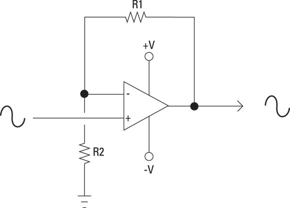

 and R2 is
  , the gain is 11. Thus, an input voltage of
  will result in an output voltage of
  .
.
 input isn’t connected to ground.
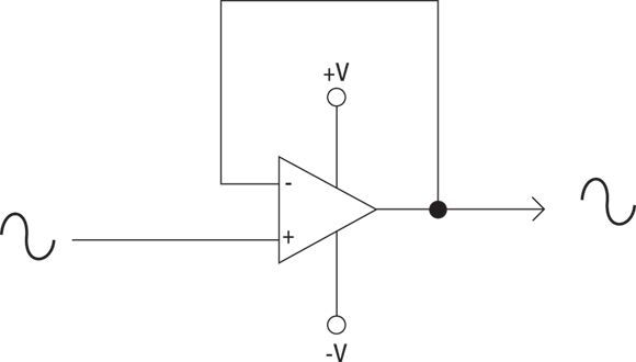

 resistors.
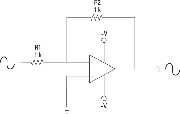
 ); then the voltage to be compared with the reference voltage is applied to the noninverting input. The output voltage depends on the value of the input voltage relative to the reference voltage, as follows:
 , the output voltage will be
  if the input voltage is greater than the reference voltage, 0 V if the input voltage is equal to the reference voltage, and
  if the input voltage is less than the reference voltage.
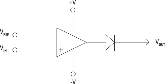
 ) input, and the reference voltage is applied to the noninverting (
 ) input.
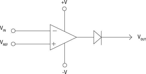
 Notice in
  and the other is
  , for example, the output voltage will be
  .
.
 and R2 is
  , for example, the input voltage applied through the
  resistor will be multiplied by 10 before being added to the voltage applied through the
  resistor. Thus, if the input at R1 is
  , and the input at R2 is
  , the output voltage will be
  . (For this formula to work, R3 must also be
  .)
.)
 and both R2 and R3 are
  :
: