Chapter 5
Introducing Microcontrollers
IN THIS CHAPTER
 Looking at microcontrollers and how they work
Examining how microcontrollers are programmed
Learning about microcontroller digital I/O pins
I first learned about microcontrollers years ago, when I wanted to create an automated prop for a Halloween display. The prop consisted of a Frankenstein creature that was attached to a pneumatic (air-powered) pop-up mechanism. Unsuspecting trick-or-treaters would walk into Frankenstein’s lab, where the creature was sitting on a big work table. After a few moments, a voice would cry out, “It’s alive! It’s alive!
It’s alive!
” and lights would flash on and off. Then the creature would start to twitch, and then pop up screaming “puttin’ on the Ritz!” As the creature popped up, a bright floodlight would illuminate him. After a few seconds, the light would go out and the creature would lie back down.
I pondered how I could create the electronic circuit to control my prop. It could be done with an old computer and relay interface that would connect to the computer’s parallel port. But I then realized it would be more fun and cost about the same to do it with a microcontroller instead of an old laptop computer and a parallel-port relay board. So I decided to build the prop using a microcontroller instead. The microcontroller would handle all the sequencing of lights and motion for the prop, and it could even play the sounds when the creature begins to awake and then finally pop up.
In a nutshell, a microcontroller
is a small computer on a single board, which you can purchase typically for less than $50. This chapter introduces you to some of
the basic concepts of microcontrollers. Then the next three minibooks show you how to work with three popular types of microcontrollers: Arduino, BASIC Stamp, and Raspberry Pi.
In this chapter, you learn several basic concepts that apply to microcontrollers of all types: what they are, how they’re programmed, and how they can be connected to the outside world via digital I/O pins. You learn the specifics of working with Arduino, BASIC Stamp, or Raspberry Pi microcontrollers in Books 6, 7, and 8.
Introducing Microcontrollers
A microcontroller
is a complete computer on a single chip. Like all computer systems, microcomputers consist of several basic subsystems:
-
Central processing unit (CPU):
The brains of the microprocessor. A CPU carries out the instructions provided to it by a program. The CPU can do basic arithmetic as well as other operations necessary to the proper functioning of the computer, such as moving data from one location of memory to another or receiving data as input from the outside world.
The CPU of a microcontroller is usually much simpler than the CPU found in a desktop computer. However, it is conceptually very similar. In fact, the CPUs found in many modern microcontrollers are as advanced as CPUs used in desktop computers just a few years ago.
-
Clock:
The CPU and other components of the microcontroller are driven by a clock that provides timing pulses that control the pacing of program instructions as they are executed one at a time by the CPU. For most microcontrollers, the clock ticks along at a pace of a few million ticks per second. In contrast, the clock that drives a typical desktop computer ticks along at a few billion
ticks per second.
-
Random access memory (RAM):
Provides a scratchpad area where the computer can store the data it’s working on. For example, if you want the computer to determine the result of a calculation (such as 2 + 2), you need to provide a location in RAM where the computer can store the result.
In a desktop computer, the amount of available RAM is measured in billions of bytes (GB for gigabytes). Microcontrollers typically have much less RAM available to them. For example, a typical Arduino processor has just 2KB of RAM. And some versions of the BASIC Stamp have just 32 bytes of RAM. One of the challenges of programming a microcontroller is often figuring out how to get your program to run with the small amount of memory available to it.
-
EEPROM:
A special type of memory that holds the program that runs on a microcontroller. EEPROM
stands for Electrically Erasable Programmable Read-Only Memory,
but that won’t be on the test.
EEPROM is read-only,
which means that once data has been stored in EEPROM, the data can’t be changed by a program running on the microcontroller’s CPU. However, it’s possible to write data to EEPROM memory by connecting the EEPROM to a computer via a USB port. Then, the computer can send data to the EEPROM.
This is how microcontrollers are programmed. You use special software on a PC to create the program that you want to run on the microcontroller. Then, you connect the microcontroller to the PC and transfer the program from the PC to the microcontroller. The microcontroller then executes the instructions set forth in the program.
Most microcontrollers have a few thousand bytes of EEPROM memory, which is enough to store relatively complicated programs downloaded from a PC.
One of the most important features of EEPROM memory is that it doesn’t lose its data when you turn off the power. Thus, once you transfer a program from a PC to a microcontroller’s EEPROM, the program remains in the microcontroller until you replace it with some other program. You can turn the microcontroller off and put it on a closet shelf for years, and when you turn the microcontroller back on, the program that was recorded years ago will run again.
-
I/O pins:
One of the most important features of a microcontroller is its I/O pins,
which enable the microcontroller to communicate with the outside world. Although some microcontrollers have separate input pins and output pins, most have shared I/O pins that can be used for both input and output.
I/O pins usually use the basic TTL logic interface that I describe throughout Book 5
: HIGH (logic 1) is represented by +5 V, and LOW (logic 0) is represented by 0 V.
Most microcontrollers can handle only a small amount of current directly through the I/O pins. 20–25 mA is typical. That’s enough to light up an LED, but circuits that require more current should isolate the higher current load from the microcontroller I/O pins. This is usually done by using a transistor driver.
Programming a Microcontroller
If you’ve never done any form of computer programming before, you’re in for a fun and fascinating adventure, during which you’ll learn a lot about how computers really work. In a nutshell, a computer program is a set of written instructions
that a computer knows how to read, interpret, and carry out. The instructions are written in a language that both humans and computers can read. The instructions aren’t quite English, but they resemble English enough that we English-speaking people can understand what they mean. (There are programming languages based on spoken languages other than English, but English-based programming languages are the most popular throughout the world.)
Computer programs are stored in text files that consist of one or more lines of written instructions. In most cases, each line of the computer program contains one instruction. Each instruction tells the computer to do something specific, such as add two numbers together or read the status of a particular input pin.
The trick of computer programming is to put the right instructions together in the right sequence to get the program to do exactly what you want it to do. Of course, to do that, you need to have a solid understanding of what you want the program to do, and you need a solid understanding of the variety of instructions that are available to you. You also must take into consideration the resources of the particular microcontroller you’re working with and what circuits or devices are connected to the microcontroller.
The most common way to program a microcontroller is to connect the microcontroller to a PC via a USB cable, write the program using a special program called an integrated development environment
(IDE), and then using the IDE to download the program to the microcontroller.
When you download the program to the microcontroller, the program is transferred into the microcontroller’s EEPROM and then executed. Once it’s in the EEPROM, you can disconnect the microcontroller from the computer. If you turn the microcontroller off or cut power to it, the program will be retained in EEPROM until you turn the microcontroller on again. In other words, the microcontroller will retain the program in its EEPROM so it can be run over and over again, even when the microcontroller is not connected to the computer. I explain how to do this for Arduino and BASIC Stamp microcontrollers in Books 6
and 7
. The procedure for Raspberry Pi devices is a bit different; I explain Raspberry Pi programming in Book 8
.
Working with I/O Pins
Most microcontrollers have several I/O pins, which you can connect external circuits to. The exact number of I/O pins varies depending on the specific microcontroller you are using.
I/O pins use the standard conventions of digital logic, which I cover in the previous chapters of this minibook. Thus, a positive voltage level of 5 V is considered HIGH, and a level of 0 V is considered LOW.
The I/O pins for most microcontrollers can handle about 20 mA of current, so you need to be sure you use current-limiting resistors in your circuits to avoid overrunning the circuit and possibly damaging the microcontroller.
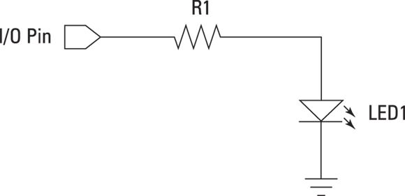
Figure 5-1
shows a simple schematic diagram for a circuit that drives an LED from pin 15 of a microcontroller. Notice in this schematic that the pin output is represented by a simple five-sided shape. It’s common in schematics to not
draw the microcontroller as a single rectangle as you would other integrated circuits. Instead, each I/O connection in the circuit is shown using the five-sided connector shape. This convention gives you plenty of flexibility in how you lay out the schematic for your circuit.