Holding Tools
Benches
You’ll need a work bench before you begin almost any sizable project. For general manual work, the ordinary bench is used by joiners as it is the most serviceable; it should be fitted with two wood bench screws and wood vice cheeks, one at each left-hand corner of the bench, to accommodate two workers. If possible, place the bench so that light falls directly on both ends—in other words, face the window while you work.
There are many good benches on the market, but do not get one that is too low, and make sure the height is right for the kind of work you intend to perform on it. The smaller benches sold at the tool-shops are not high enough for an adult—from 33 to 34 inches is great for an adult, while 26 to 30 inches will suit younger workers. Choose a bench that is high enough to give you the most command over your tools. You should be able to work conveniently without having to stoop; but the height of the bench should not prevent you from standing well over your work (see Figure 60). A height of 2 feet 6 inches might be just right for occasional use, but too low to work at for any length of time. A simple method of raising it slightly from the floor is to put a piece of quartering under each pair of legs. For heavy work the bench may have to be fixed to the quartering, and the quartering to the floor, for which purpose stout screws or screw bolts will do. Figure 60 shows the relative heights of worker and bench.
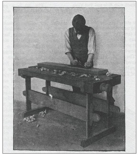
Figure 60—Workman and Bench
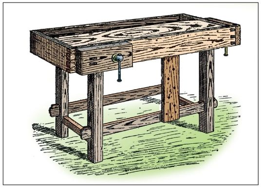
Figure 61—Bench with Side and Tail Vices
Various Kinds of Benches
Figure 61 shows a general view of a simple bench with side and tail vices. This form is extremely useful for cabinet making and similar work, where it is helpful to hold pieces of material that may have to be planed, molded, chamfered, mortised, grooved, etc., without using a bench knife or similar method of fixing. The material could be held between stops, one being inserted in one of the holes in the top of the bench and another in the hole made in the cheek of the tail vice. The following dimensions are only suggestions and the bench may be made longer or shorter, narrower or wider, to meet your needs: Top, 5 feet by 1 foot, 9 inches, and 2 inches thick. Height, 2 feet, 7 inches. Distance between legs, 3 feet, 2 inches lengthwise, and 1 foot, 3 inches sideways. Legs, 3 inches by 3 inches. Your bench should be constructed of hard wood, such as beech or birch, and in any case it will be best to have hard wood for all the parts forming the top, side cheeks, and cheeks of vices, as these are the main parts of the bench; consider choosing red deal for the framing of the legs, rails, etc. A simple bench is illustrated by Figure 62; this is a suitable model for general carpentry and joinery. The framework is made of a thoroughly seasoned dry spruce fir or red pine, and the top of birch or yellow pine.
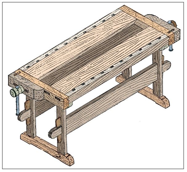
Figure 62—Double Bench with Vice at each end
The folding bench illustrated in Figure 63 will be found useful in cases where a portable bench is required for occasional use only. When not using the bench, the screw, screw cheek, and runner can be taken out, the legs folded on to the wall, and the top and side folded down as seen in Figure 64. You will find a more elaborate bench for cabinet work in Figure 65; it consists of two principle parts, the underneath framework and support, and the top. The former has two standards joined by two bars. On the feet of the standards rests a board which serves to hold heavy tools and other articles. There is a rack for small tools and underneath this a band, tacked at short intervals, for other tools. The front rail has holes on its top face 1 inches by ¾ inches for holding bench stops, while in the front face of the rail are round holes for holding other pins, illustrated by T, 1½ inches square at one end, but made round at the other end to fit tightly into the holes. The pin T and the block v (Figure 65), screwed on the end of the moveable jaw of the vice, serve to hold wood during the process of edge planing. Holes in the back rail receive pins w which are convenient for cramping up joints. A kitchen table bench is shown in Figure 66. The end of the table employed is not the one containing the usual drawer. Two blocks of wood A B, 3 inches square, are attached to the table top by two cramps embedded in the ends of one of the pieces. Through mortise holes c c are inserted slats glued and wedged to block A, but running loosely in holes in B. s is a screw, and the two parts of the bench serve the purpose also of vice cheeks; though if desired the two blocks can be screwed together solid.
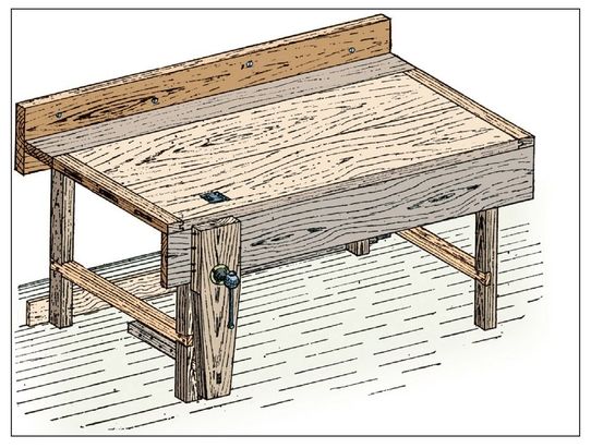
Figure 63—Folding Bench in use
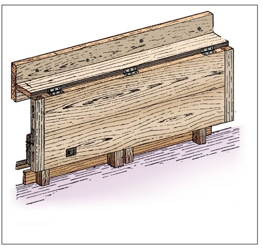
Figure 64—Folding Bench not in use
Bench Stops
Generally, store-bought benches are provided with holes for the reception of stops that allow for work to be held for planing, etc. These stops are made of iron and shaped as in Figure 67, and have springs at their sides by means of which they are held tightly and at any required height in the bench holes. You will find an adjustable stop for screwing to the bench in Figure 68. For a temporary stop some workers drive a few nails into the bench end, leaving the heads projecting enough to hold the wood. A better substitute can be made out of an ordinary butt hinge, one end of which should be filed into teeth so as to hold the wood better. Be sure to leave this end loose, and screw the other end down tightly to the bench end as shown by Figure 69. A long, light screw through the middle hole in the loose side will afford sufficient adjustment for thin or thick work. When you are finished, the hinge can be taken up and put away.
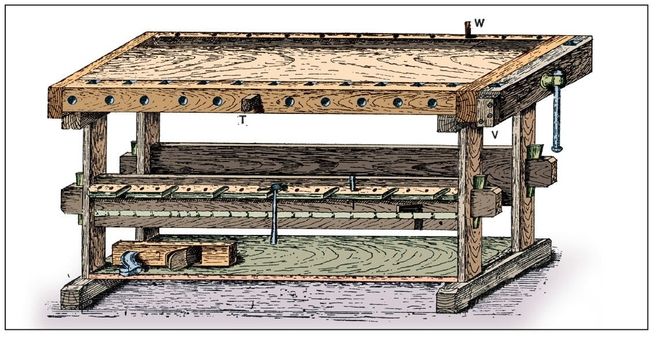
Figure 65—Cabinet-worker’s Bench
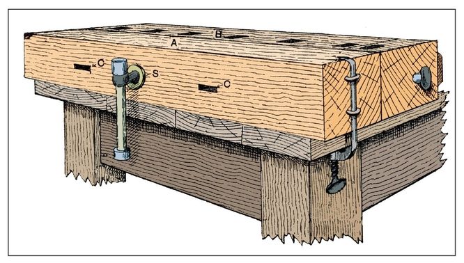
Figure 66—Kitchen Table Bench
Common Bench Screw Vice
A common form of joiner’s bench screw is shown in general view by Figure 70 and Figure 71 is a sectional view. D is the side or cheek of the bench to which the wooden nut A is screwed. The box B, which accurately fits the runner shown inside it, is fixed to the top rail connecting the legs, and to the top and side of the bench. Be careful to keep the runner at right angles to the vice cheeks. To fasten the vice outer cheek and screw together so that upon turning the cheek, the screw will follow, cut a groove shown by Figure 71. Then from the under edge of the cheek, make a mortise and drive in a hardwood key, F, so that it fits fairly tightly into the mortise and its end enters E. The screw cheek is usually about 1 foot, 9 inches long, 9 inches wide, and 2 inches to 3 inches thick. The runner is about 3 inches by 3 inches and 2 feet long. You can also buy the wooden screws and nuts ready made.
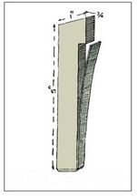
Figure 67—Iron Bench Vice
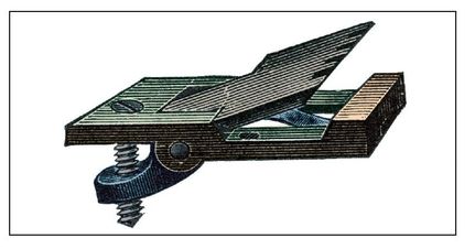
Figure 68—Adjustable Bench Stop

Figure 69—Hinge used as Bench Stop
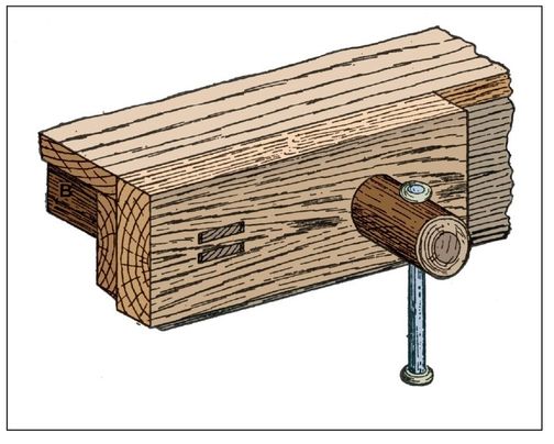
Figure 70—Bench Screw Vice
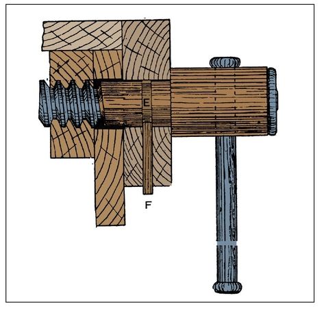
Figure 71 Section through Screw Vice
Screw Vice for Kitchen Table
Figures 72 to 74 show a simple device for fixing a screw vice to a kitchen table, the vice being detachable for removal as required. The device illustrated does not cause the least degree of damage to the table. A hole is made in the table leg for the screw to pass through, the nut or box of which is fixed to the back of the leg as shown. Two hardwood runners, 2 inches by ¾ inch by 1 foot, 8 inches, should be made and dovetailed into the screw cheek, which is 2¼ inches thick, 1 foot, 3 inches long, and has its breadth regulated by the size of the leg. The distance between runners should be the same as the thickness of the leg. The runners are kept in position by two blocks A and B, which are screwed to the back of the leg. An adjustable pin c made from a piece of ½-inch round iron, will be required, and must be sufficiently long to pass through both runners. Screw a block, D (Figure 73), to the leg, the face of the block being flush with the front edge of the top.
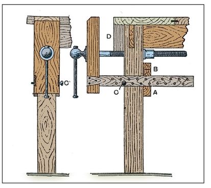
Figures 72 and Figures 73—Kitchen Table Screw Vice
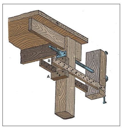
Figure 74—Side General View of Kitchen Table Vice
Sawing Stools or Trestles
Figure 75 shows a standard sawing stool, Figure 76 is a side elevation, and Figure 77 an end elevation. Suggestive sizes are figured on the drawings. The thickness of the material can, of course, be increased or decreased according to requirements. The simplest sawing stool, but the least reliable, is the one with three legs shown by Figure 78, but this is of little service and almost useless. Better and more usual forms are shown by Figures 79 and 80, these being about 20 inches high, firmly and stiffly made. In Figure 79 all the parts are mortised and tenoned together, and strutted to give strength, but in Figure 80 the legs are simply shouldered and bolted into the sides of the top. The cross stretchers are slightly shouldered back and screwed or bolted to the legs.
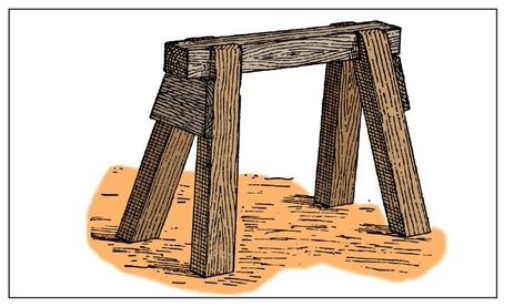
Figure 75—Common Sawing Stool
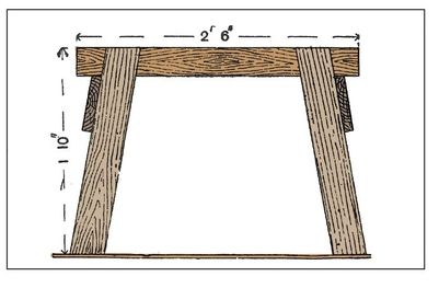
Figure 76—Front Elevation of Sawing Stool
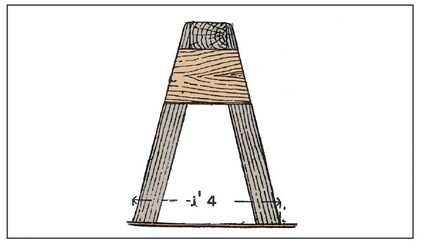
Figure 77—End Elevation of Sawing Stool
Cramps
Cramps are used to hold work on the bench, to hold together work in course construction, to facilitate the making of articles in which tight and accurate joints are essential, and to hold together glued joints until the glue is dry and hard. A holdfast for temporarily securing work to the bench is shown in Figure 82. This ranges in length from 12 inches to 16 inches. The old-fashioned holdfast cramp is illustrated by Figure 83; this is made entirely of wood, and the cheeks of the cramp range in length from 6 inches to 16 inches. Iron cramps are shown by Figures 84 and 85, where Figure 84 is the ordinary G-cramp. Figure 85 shows one of Hammer’s G-cramps with instantaneous adjustment, this being an improved appliance of some merit. The screw is merely pushed until it is tight on a work held in the cramp, and a slight turn of the winged head then tightens up the screw sufficiently. The sliding pattern G-cramp is illustrated by Figure 86, this possessing an advantage similar to, but not as great as, that of Hammer’s cramp. Sash cramps and jointers’ cramps (non-patent) resemble Figure 87. There are several makes and many differences in detail, but Figure 87 illustrates the type. There are a number of patent cramps for sashes and general joinery, but Crampton’s appliance (Figure 88) is typically sufficient. You can set the right-hand jaw at any position on the rack. After you insert the work, push the right-hand saw against it tightly and the lever handle adjusts instantly. When you joint up a thin project with an ordinary cramp, there is a great risk of the material buckling up and the joint being broken. You can easily avoid this risk by using a cramp which is sufficiently explanatory when it is said that the cross pieces slide upon the side pieces, one sliding bar being made immovable by iron pins placed in holes in the side pieces. In cramping very thin projects, place a weight upon it before finally tightening the hand screw.
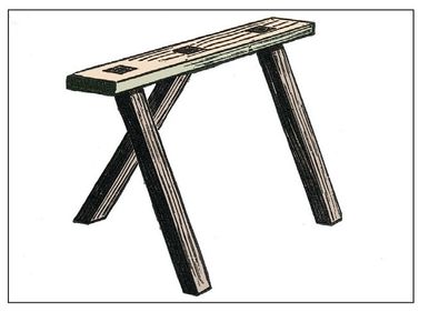
Figure 78—Three-legged Sawing Stool
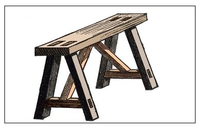
Figure 79—Braced Sawing Stool
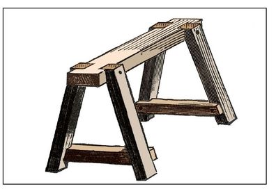
Figure 80—Bolted Sawing Stool
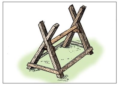
Figure 81—Sawing Horse
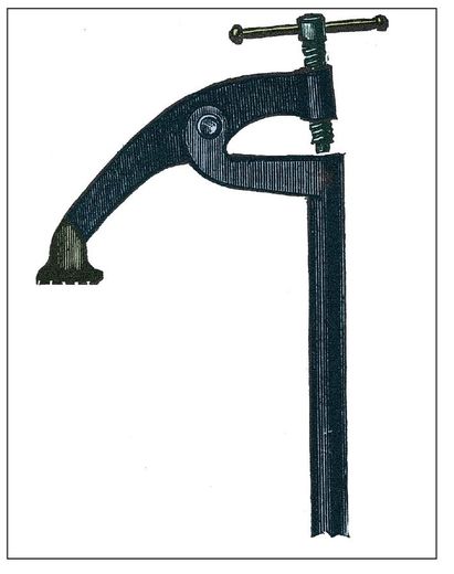
Figure 82—Bench Holdfast
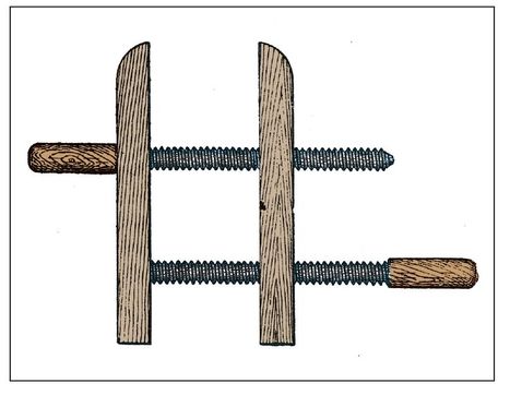
Figure 83—Wooden Holdfast Cramp
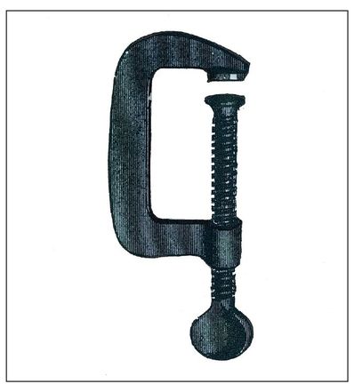
Figure 84—G-cramp

Figure 85—Hammer’s G-cramp
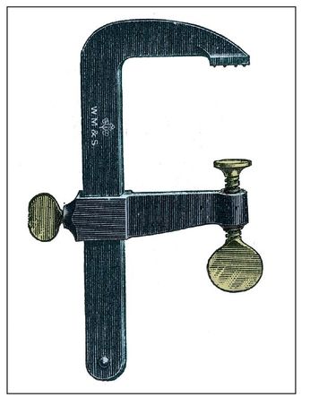
Figure 86—Sliding G-cramp
Rope and Block Cramp
To cramp up boards with ropes and blocks, place the wood blocks A about 4 inches long, and 1½ inches square, on the edges of the boards B, and place a rope around them twice and make a knot. Then place a small piece of wood between the two strands of rope and twist it around. This twisting draws the rope tighter on the blocks, thereby cramping the boards together. Three of these sets would be sufficient to cramp a number of long boards.
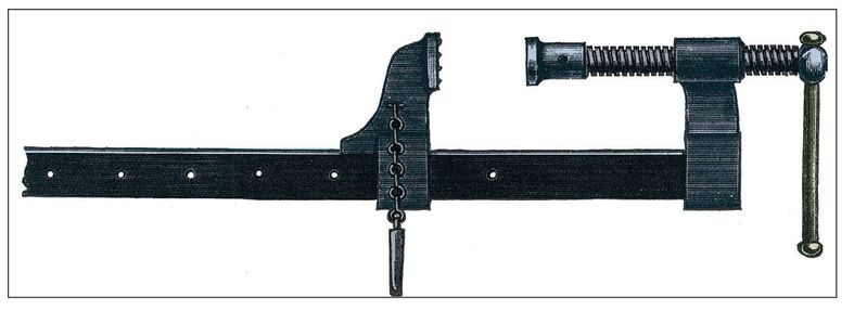
Figure 87—Sash Cramp

Figure 88—Crampton’s Patent Cramp
Cramping Floor Boards
Floor boards are commonly cramped or tightened up using “dogs,” of which two forms are shown respectively by Figures 89 and 90. The boards being already close together, the dog is inserted across at a right angle to the line of joint, one point being in one board and one in the other. The further you hammer in the dog, the closer the boards are cramped together. Floor boards can be tightened up without using a floor dog with the method illustrated in Figure 91. The board next to the wall should be well secured to the joists, and then three or four boards can be laid down and tightened up by means of wedges, as shown. The following is the method of procedure: Place a piece of quartering about 2 inches by 3 inches next to the floor board, as at c. Cut a wedge, and place it at B, then nail down a piece of batten to the joists, as at A (both this and the wedge can be cut out of odd pieces of floor board). The wedge B should be driven with a large hammer or axe until the joints of the board are quite close.
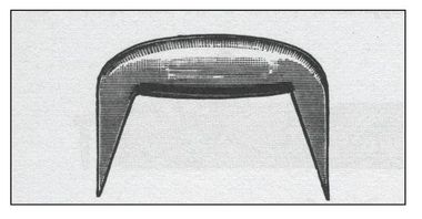
Figure 89—Dog, Round Section
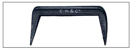
Figure 90—Dog, Square Section
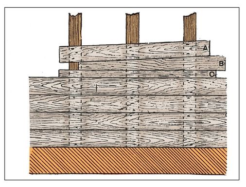
Figure 91—Wedge Cramp for Floor Boards
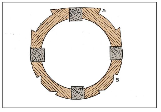
Figure 92—Circular Seat with Cut Cramping Pieces
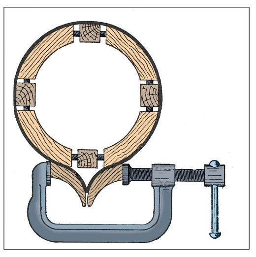
Figure 93—Circular Seat with Flexible Cramp

Figures 94 and Figures 95—Wood Horn of Flexible Cramp
Pincers
Pincers are used for extracting and beheading nails, and for other purposes where a form of hand vice is wanted for momentary use. There is little variety in their shape, and they range in size from 5 inches to 9 inches Usually one handle ends in a small cone (see Figure 96) or ball (See Figure 97), and the other in a claw for levering out nails, etc. Figure 96 shows Lancashire pincers, and Figure 97 Tower Pincers.

Figure 96—Lancashire Pincers

Figure 97—Tower Pincers
