Sheds, Tool Houses, and Workshops
Open Shed or Hay Barn
The shed or hay barn described below can be made by anyone able to use an axe and saw. Figure 195 is an isometric sketch of the frame, and Figure 196 is an end view. The posts A go into the ground about 4 feet, rise above it about 15 feet, and are about 8 inches square at the bottom and taper to 6 inches at the top. Each post can be sawn or chopped and must have a tenon about 4 inches long, 3 inches wide, and 1½ inches thick, cut on the top end, or the tenon may be left the whole width of the post. Plates B, preferably of yellow deal, should be about 6 inches by 4 inches, and mortised to fit the tenons, allowing them to reach about 6 inches over the end posts. If the proposed building is of such a great length that the plates have to be spliced, the splicing should be done by making a halved joint, not less than 1 foot in length, the joint, of course, to rest on one of the posts. Ties c should be from 6 inches by 4 inches to 9 inches by 4 inches, according to the length of the building. The former dimensions will work for a structure up to 14 feet wide and the latter will do up to 20 feet wide. The king-post D should be 6 inches by 4 in, no smaller, whether the building is wide or narrow. It should be tenoned into the center of the tie, as illustrated. The braces E, 3 inches square, can be placed as shown in the two end trusses, or the middle ones can be shorter. These don’t need to be mortised or tenoned if they are strongly nailed. The ridge F, 3 inches by 3 inches, should lie in slots cut in the tops of the king-posts. If it has been spliced, the splicing should be at one end of the posts, as in the case of the plates. The ties c should be dovetailed to the plates B, as in Figure 197, which shows the plate cut at G and dovetail H on the tie. These should all be fitted and numbered before you put up the posts. The king post, braces, and ridge should also be fitted in their respective places, but as yet nothing should be permanently fixed.
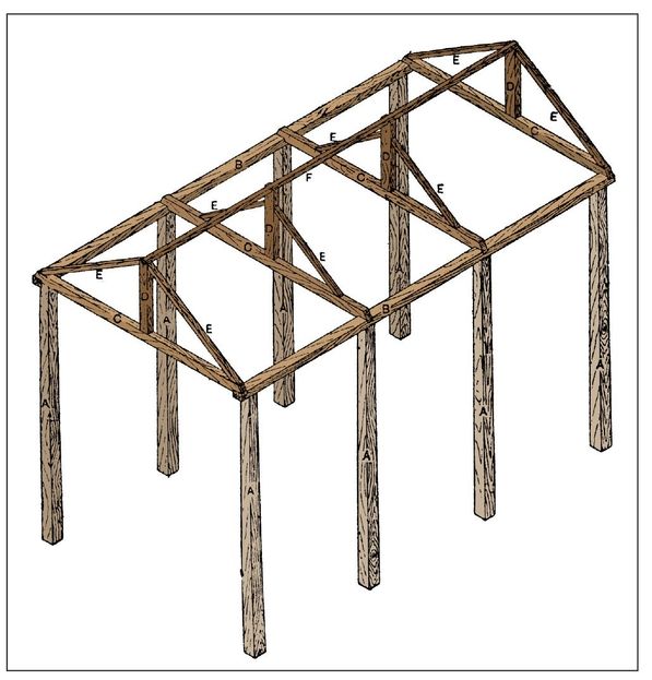
Figure 195—Framing for Hay Barn
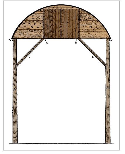
Figure 196—End Elevation of Hay Barn
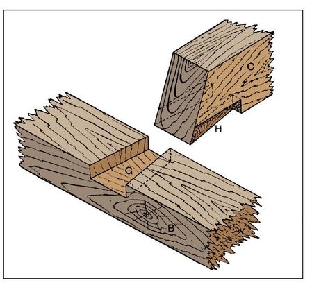
Figure 197—Tie Dovetailed to Plate
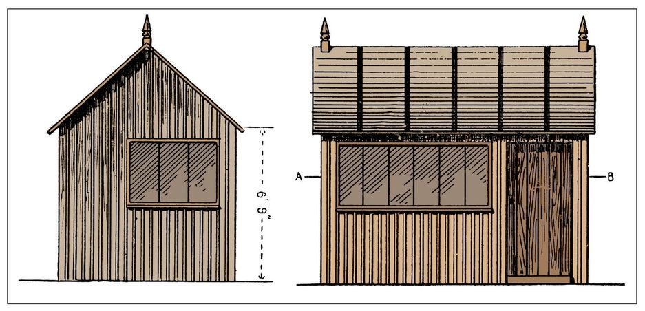
Figures 198 and Figures 199—Elevations of Gable-roof Tool House
Erecting the Hay Barn
After digging the necessary holes, the posts should be placed along one side and propped up to prevent them from falling. The plate for that side can then be put on the tenons at the top and pinned, the pin-holes having already been bored. The two end posts should then be adjusted so that they stand upright and parallel, and that the plate is about level from end to end. Afterwards, ram the two posts up tightly, and then raise or lower the intermediate ones as required. The other posts can be put up in the same way, except that as soon as the plate is on and pinned, the ties should be put on as well. It will then be easy to regulate the width, which should be the same at the top and bottom. If the ties are fitted as they should be, they will ensure the building being square at the angles when finished. After the king-posts, braces, and ridge have been properly adjusted, the structure will be ready for the roof, which you should make of corrugated iron, as shown in Figure 196, rolled to a segment of a circle. You should preferably use lengths that will require three to reach over from eaves to eaves, allowing 6 inches for each of the two laps. These sheets must be fixed together with short bolts while on the ground. They can be placed in position to form the roof by nailing or screwing them to the ridge and plates. Let them overhang 6 inches at each end of the building. When the roof sheets have been put on, two pieces of quartering I (Figure 200) must be fixed at each end of the barn. They can be tenoned into the ties, and the braces or rafters cut away so that the upright pieces fit inches On these two pieces are nailed two other pieces, 1¼ inches thick and 1 inch narrower than the quarterings, so as to leave a rebate on the outside, to which the weather-boarding N is then nailed. The 1¼-inch pieces at K (Figure 196) serve as stops for the ends of boards. Fit the weather-boarding close up to the corrugated-iron sheets—at the top, allowing about two boards to run straight across as shown. The space between the two pieces K is filled in with folding-doors M, made to open outwards. These, when the barn is full of hay, can be opened to allow a current of air to pass through , and also to ventilate the building. Braces L (Figure 196) can be fixed next, not only at the ends but between each pair of posts. Mortise them into the posts with a stub tenon, and nail them to the ties and plates at the top. This method will be stronger and more convenient than nailing at both ends. If a large barn is built, it should be made high enough to admit of loaded wagons being drawn in between the side posts.
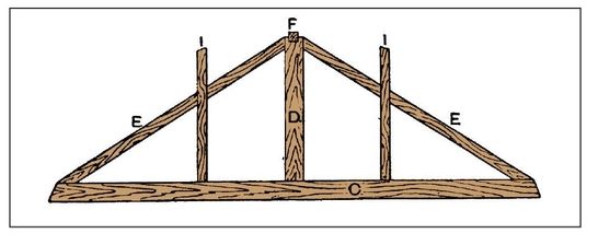
Figure 200—End Truss of Hay Barn
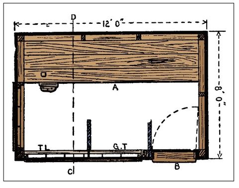
Figure 201—Horizontal Section of Tool House
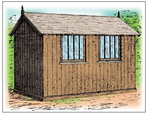
Figure 202—Portable Span-roof Workshop
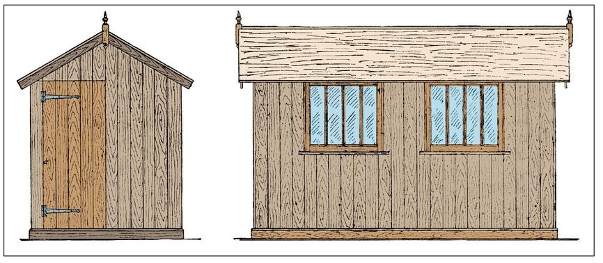
Figures 203 and Figures 204—Elevations of Span-roof Workshop
Portable Span-roof Workshop
Figure 202 is a perspective view of a portable workshop constructed so that the floor forms one piece with the joints and curb, the ends and sides each form a section, and each side of the roof can be of one or more pieces as desired. The ends are attached to the sides by the angle posts meeting and being held together by three ½-inch bolts. For neatness, all the wood should be planed. Figures 203 and 204 are elevational view, and at Figure 205 the skeleton framework is shown. The quantities of material required are as follows:
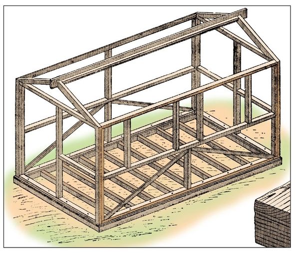
Figure 205—Workshop Framing
- Curb, 38 feet of 3¼-inch by 3¼-inch
- Joists, 48 feet of 3-inch by 2-inch
- Uprights, 77 feet of 2½-inch by 1½-inch
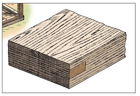
Figure 206—Corner Joint of Curb
- Rafters, braces, and bottom rails, 41 feet of 2½-inch by 1½-inch
- Ridge, 13 feet of 6-inch by 1-inch
- Bargeboards, 16 feet of 3½-inch by 1-inch
- Plinth, 38 feet of 5-inch by ⅞-inch
- Floorboarding, 132 feet of 7-inch by 1-inch
- Matchboarding, 638 feet of 6-inch by ¾-inch
- Finials, 3 feet of 2½-inch by 2½ inch
- Ridge fillets, 26 feet of 2½-inch by 1-inch
- Roof ledges, 52 feet of 4-inch by 1-inch
- Door ledges, 7 feet 6 inch of 5-inch by 1-inch
- Window sills, 7 feet 6 inch of 4-inch by 1½-inch
- Window stiles and top rail, 18 feet of 2-inch by 1½-inch
- Window bars, 15 feet of 2-inch by 1¾-inch
- Middle rails, 33 feet of 2½-inch by 2-inch
- Bottom and end rails, 48 feet 2½-inch by 1½-inch
- Side plates, 24 feet of 3-inch by 2½-inch
- Outside bead, 12 feet of ¾-inch by ¾-inch
- Inside bead, 24 feet of 1-inch by ⅝-inch
Beginning with the floor, the curb forming the outside frame should be halved together, as seen in Figure 206. The joists should be notched into the curb, and when fitted these parts should be secured by nails. Probably the best material for the floor will be 1-inch grooved and tongued floorboards cut to length and nailed down with close joints, the boards extending to the outside of the curb all round (See Figures 206 and 207). The framework of each end should be mortised and tenoned together. The top plate of the front and back is splayed off to the same angle as the roof. The outside of the framing should be covered with ¾-inch machine-prepared matchboarding, and to improve the appearance of the inside the backs of the boards should be smoothed over before being fixed to the framing, the beaded sides being outward. Figure 208 shows the boards of the sides A and ends B projecting over the angle posts. The door may be formed of five boards with three ledges nailed across the inside, and can be hung with a pair of 18-inch cross garnets (See Figure 203). Any suitable fastener may be used. Two pieces, 4 inches by 1½-inches, should be prepared to the section at c (Figure 207) and cut to fit between the window posts, projecting at each end as shown by Figures 202 and 204. Two sashes with three bars may be used; They are of very simple construction, being mortised and tenoned together, and rebated, either on the inside or on the outside as desired. This kind of sash may be hung to the top of the framework; it may then be pushed out at the bottom, and held open by means of a small iron stay. To keep out the draught and form a stop to the sashes, pieces of ⅝-inch by 1-inch bead should be mitered round, and fixed to the framing with a few 1½-inch nails. The outside vertical angles of the windows can be finished with beads as shown at Figure 209.
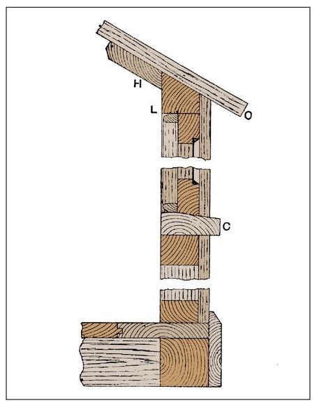
Figure 207—Section of Workshop Window
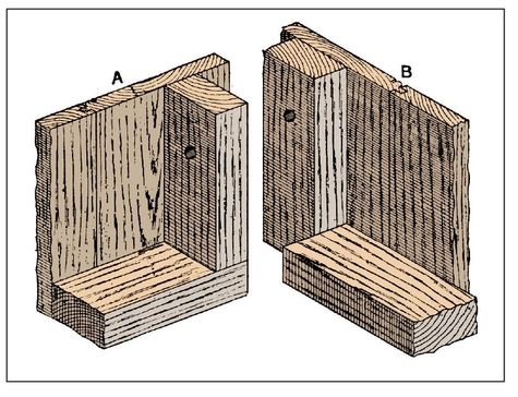
Figure 208—Corner Posts, Sills, and Boarding

Figure 209—Part Horizontal Section of Workshop Window
Portable Workshop with Slant Roof
The workshop illustrated in Figure 210 has a boarded floor, and is so arranged as to be a tenant’s fixture, and to be easily taken down and re-erected as needed. It is made of six separable pieces, namely roof, two sides, two ends, and floor; or in some cases, the wall might serve the purpose of one side, and only five pieces will need to be constructed. The following are the quantities of timber needed:
- Floor frame, 38 feet of 3-inch by 3-inch
- Joists, rafters, and framing, 240 feet of 3-inch by 2-inch
- Floorboards, 156 feet of 6½-inch by ⅞-inch
- Side frame, 24 feet of 3-inches by 1½-inch
- Matchboarding, 466 feet of ¾ inch
- Sashes and skylight, 34 feet of 1½-inch by 9-inch board
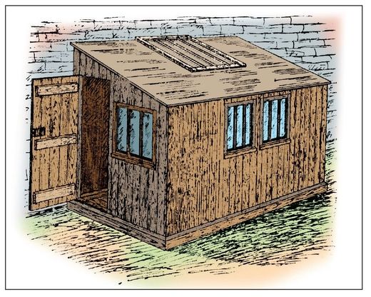
Figure 210—Portable Slant-roof Workshop
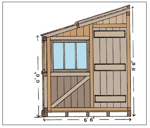
Figure 213—Section showing Workshop door
As the drawings show the construction very thoroughly, it is not necessary to give lengthy description here, but only the particulars of construction. Figure 211 is an inside elevation of one side, Figure 212 a section of line A A in the previous figure showing the inside of one end, Figure 213 a section on line B B showing the inside of the end containing the door, and shows at A a half-plan with joist and framing of floor, and at B a half-plan of roof with rafters, part of skylight, and part of boarding. The four outside pieces of the floor should be formed of 3-inch by 3-inch timber, half lapped together at the angles. The joints may be 3 inches by 2 inches, notched into the outside pieces. All the joints should be firmly fixed together with 2½-inch nails. Prepared floor-boards will be preferable for the floor, and if you are willing to pay an extra expense, have them grooved and tongued. The boards should be fixed to the joists and sills with 2-inch or 2½-inch floor-boards. The edges of the boards should finish flush with the outside.
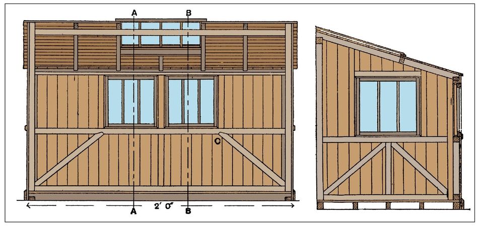
Figure 211 and Figure 212—Sectional Elevations showing Side and End of Workshop
Log Huts or Cabins
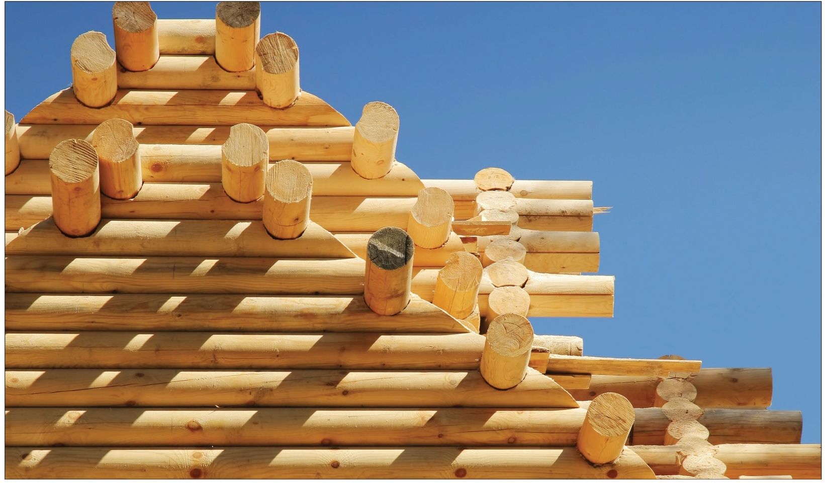
In some surroundings, if rough timber is cheap, a log cabin or hut would make a strong tool shed. Log huts are built all over the world in different degrees of finish and comfort, according to their purpose and to the ingenuity of the owner. As a rule, the logs are notched with an axe at a short distance from each end, and built up in alternate pairs to form the walls, and cut short wherever door- or floor-frames occur. The interstices between the logs may be filled up with branches, cemented with clay, and finished with a finer plaster; but in more pretentious buildings the crevices are blocked up neatly with triangular pieces split from logs and nailed to the walls; the inside can then be close-boarded. If a fireplace is required, the best material for it is stone; however earth or bricks work as well. The chimney-flue may be formed outside the hut with a wood shafeet In the backwoods the stripped trunk of a tree is used as a core for the flue, inserted temporarily in the center of the shaft; clay is then rammed in round it, and when the flue is formed the tree trunk is drawn out at the top. The fireplace is made by cutting a square hole in the logs just above the floor, forming a wood shaft at the bottom of the flue, and lining inside with clay to a good shape. Then all the clay is coated with a plaster of gravel and clay, cowdung, and water; this could be improved upon owing to other and better materials being available. As for the roof, it should be high pitched, and have deep eaves. Figure 214 shows a section, A indicating tie-beams, 2 feet or 3 feet apart; B, wall-plates notched and pinned on to beams; c, rafters, same distance apart as the tie-beams, and secured to them; D, collars spiked to rafters; E, ridge-pole tied with withies to the rafters. Nail battens on the rafters, and cover with shingles. Figures 215 and 216 show a common form of log cabin built up in much the same way. The logs are notched together and further secured by boring with an auger through each log into the last log fixed, and driving in a wooden pin or nail. If you require a chimney, it should be built of some local stone or similar material, but stoves with piping are often made to serve the purpose. The roof is often formed by splitting the logs into two and is covered with material that will render the roof waterproof. Figure 217 is a plan of the log hut.
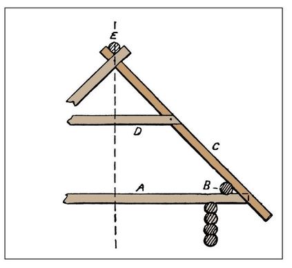
Figure 214—Section of Log Hut Roof
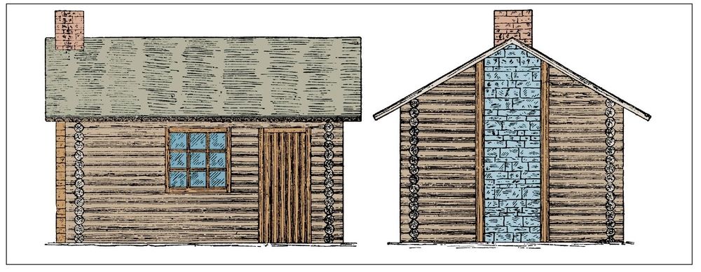
Figures 215 and Figures 216—Elevations of Log Hut or Cabin
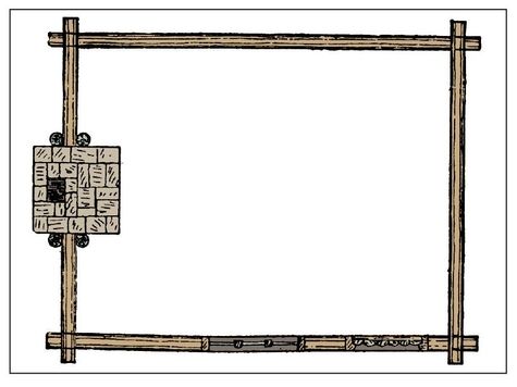
Figure 217—Plan of Log Hut or Cabin
