Kitchen Furniture
Kitchen Corner Cupboard
A small corner cupboard as illustrated in Figure 218 will be found very useful, and can be quickly built. The body, outer frame, and door frame can be made from ¾-inch prepared material, to save planning up. You won’t need any mortises, grooves, or rebates. Figure 218 gives a general view of the body. To make the body, cut from some 8-inch by ¾-inch material four 2-feet 6-inches lengths. Nail small cleats or battens across them (See c, Figure 219); these will make the two parts that form the back of the cupboard. Figure 220 shows a plan of top and bottom; these should be cut from ¾-inch stuff. Two shelves must be cut from ½-inch or ⅝-inch prepared material to the shape of the top and bottom, but  inch less from front to back. This will allow the door frame to come flush with the outer frame when the door is closed. The four pieces referred to being cleated, and the top, bottom, and shelves cut to their proper shape and size, nail the two parts that form the back to the top and bottom; Then place the shelves on the cleats c c, nail with small wire nails, and the body is finished, except for planning the front edges of the back a little, so that the outer frame may lie flat and even against it.


Figure 218—Kitchen Corner Cupboard
Outer Frame of Corner Cupboard
The outer frame is made from ¾-inch material like so: Cut off two 2-feet, 6-inches lengths, and two 2-feet, ½-inch lengths; these should be 2½ inches wide. Halve the ends, and nail these together, and the frame F (Figure 218) is made. A small portion of the frame is cut away with a chisel to receive two butt hinges. This frame is nailed against the front of the body, and the outer edges of the frame are planed to correspond with the angle of the back of the cupboard. The door frame is made from material 2 inches wide, and the ends are halved and put together as the outer frame, which should thus fit nicely within the outer frame. On the inside of the door frame a piece of pine of suitable length and width, and about  inch thick, nicely planed up, is nailed to the frame, seen in Figure 221; This piece forms the door-panel and at the same time tends to strengthen the door frame, and looks as well from the outside as if the frame had been mortised and tenoned together, and the panel let into a rebate in the frame. Secure two 1½-inch butt hinges, as shown. Hang the door D (Figure 218) to the outer frame by securing the hinges H H. Fix a knob and fastener as shown in Figure 218, then fill in the nail-holes with putty, and rub up the outer frame, door frame, and panel with glasspaper; then the cupboard may be stained, sized, and varnished, or painted.

Figure 220—Top or Bottom of Corner Cupboard

Figure 219—Shelves of Corner Cupboard

Figure 221—Corner Cupboard Door
Household Tidy
A small cabinet should prove most useful. Figure 222 is part front elevation, part section. In Figure 223, which is a section on N N (Figure 222), A is one of a pair of vertical side pieces, into each of which a shelf B is housed. A top c is joined as shown in Figure 222. A back may be fitted in by grooving the inner edges of the sides, or by rebating and screwing on a strip as in Figure 224. Two small doors hinged to the sides are framed up and paneled flush on the inside. Figure 225 shows a section of them at the meeting stiles. The piece D (Figure 223) should be screwed from behind. E (Figure 222) is a strip to carry hooks for keys, and F (Figure 223), to which this strip is fastened, is screwed to the shelf. A space G (Figure 222) is divided centrally, and is useful for holding small books, etc. The spaces H (Figure 222) may receive small drawers, which may be made of tobacco boxes with the lids removed, and with wooden fronts L (Figure 223) screwed through holes punched in the front of the boxes. Small compartments J (Figure 222) are closed by sliding fronts pierced by center-bit holes, as indicated by the dotted circle. Each space may contain a ball of string, the hole being used help remove the front and admit one end of the string. The vertical portion K is carried well up so that a gum or paste-pot with a protruding brush may be protected if placed in the recess at the side. The inside of each door has a strip of leather near the top fastened transversely (Figure 226), and in the loops formed some such article as a hammer, screwdriver, or sardine-tin opener may be placed. You will find this very handy for many household tools. The cabinet may be hung to the wall by eye-plates, attached one on each side at about the level of M (Figure 222). The total width of the article is 17 inches, the height is 23 ¼ inches, and the depth is 6 inches.

Figure 222—Part Elevation and Section of Tide

Figure 223—Cross Section of Tidy

Figure 224—Back of Tidy Jointed to Side

Figure 225—Section through Door Meeting Stiles

Figure 226—Looped Leather Strip
Spice Box with Drawers
To make a spice box like the one in Figure 227, yellow pine or deal is the best material, but, in any case the wood must be thoroughly dry. The following pieces will be required:
- Back of case, one piece 7¾ inches by 6½ inches by ¼ inch
- Sides, two 7¾ inches by 3 inches by ¼ inch

Figure 227—Spice Box with Drawers
- Top and bottom, two 7¾ inches by 3¼ inches by ¼ inch
- Shelves, four 6½ inches by 2⅝ inches by
 inch
inch - Partition, one 6⅛ inches by 1 inch by ¼ inch
- Ornament, one 7¼ inches by 1¼ inches by ¼ inch
- Sides of drawers, eighteen 2⅜ inches by 1⅛ inches by
 inch
inch - Back of small drawers, eight 2⅝ inches by 1⅛ inches by
 inch
inch - Front of small drawers, eight 3 inches by 1⅜ inches by ¼ inch
- Bottom of small drawers, eight 3 inches by 2⅜ inches by
 inch
inch - Back of bottom drawer, one 5⅞ inches by 1⅛ inches by
 inch
inch - Front of bottom drawer, one 6¼ inches by 1⅜ inches by ¼ inch
- Bottom of drawer, one 6¼ inches by 2⅜ inches by
 inch
inch

Figures 228 and Figures 229—Spice Box Sides
These are all finished sizes. The other materials required are nine small brass knobs, two bracket eyes, four wooden feet, and a handful of small nails. To make the case, cut the two side pieces to the shape shown by Figure 228. Cut four grooves (Figures 228 and 229) ⅛ inch deep and 2½ inches long, to fit in the shelves, and treat the back edge of these pieces in the same manner. The width of the grooves is just sufficient to allow the shelves to fit tightly into them. At equal distances from each other carefully mark out the positions for the grooves by dividing the side piece into five equal parts. The places for the grooves being determined, draw lines across representing the widths of the grooves; then cut these lines down to a uniform depth with a chisel, cutting downwards, or guided by a straightedge, draw it along to that it cuts into the wood. The bottoms of the grooves need not be absolutely smooth, as they are not seen when the parts are fitted together. Nail the top and bottom on to the sides. The feet can be put on at the same time by driving the nail first through the foot (see Figure 230). When you complete the case, it should measure inside 7¾ inches by 6 ¼ inches. Next take three of the four shelves and cut them as shown by Figure 232. The piece cut from the middle is 1 inch long and ¼ inch wide. The pieces cut from the sides are ⅜ inch long, and ⅛ inch wide. The fourth and bottom shelf is cut similarly, only the middle piece is left in. Fit the shelves and partition into their respective places, the partition being nailed to the top of the case and to the bottom shelf. If the back is now fixed in its place, the case (Figure 233) may be considered complete. All that’s left to be done is to make the drawers. The front of the drawers should be cut so that the sides will fit into them as in Figure 234. After making the drawers, fix a knob on each to serve as a handle for pulling them out. If the remaining piece is cut to the shape shown in Figure 235, a passable ornament will be the result. It is fixed to the top by nails driven down into the two side pieces. By fixing two bracket eyes to the back, the box can either be hung against the wall or stood in any convenient place. To add a finish to the box it can either be stained or polished, or painted—according to your taste.
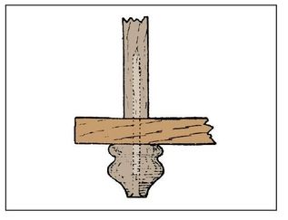
Figure 230—Spice Box Foot

Figure 231—Vertical Outline of Spice Box

Figure 232—Spice Box Shelf

Figure 233—Spice Box Case

Figure 234—Part of Spice Box Drawer

Figure 235—Top of Spice Box

Figure 236—Plate Rack

Figures 237 and Figures 238—Front and End Elevations of Plate Rack
Pantry Safe or Cupboard Pantry
Figure 239 is a front elevation of a pantry safe which is rectangular in plan, and Figure 240 shows the end elevation. For the three pieces of framing, six stiles, 2 feet, 8 inches by 2 inches by 1 inch will be required. These pieces are mortised and tenoned together, the six top and bottom rails having haunched tenons, as shown in Figure 241. The other three rails have tenons and the pieces of framing are glued and wedged together. The two framings for the ends are rebated ½ inch each way on the back edges to receive the back, which is formed of 3-inch by ½-inch tongue and groove-jointed matchboarding. The front edge of the ends has a ¾-inch chamfer on the outside corners. The shelves and top should be got out of a wide board of pine or whitewood. The top, when finished, is 1 foot, 10½ inches long and 1 foot, 6 inches wide, which allows it to project ¾ inch over the front and ends. The projecting should either have a nosing worked on, as shown in Figures 239 and 240, or a chamfer. The shelves are 1 foot, 3¾ inches wide by 1 inch thick, supported by four fillets, 1 foot, 3¾ inches by ¾ inch by ½ inch, screwed to the sides of the safe as shown in Figures 243 and 244. In fixing together, the top may be secured to the ends with 1½-inch screws three through each top rail. The bottom shelf is fixed with screws to the fillets, thus securing the lower ends of the sides as shown in Figure 244.

Figure 239 and Figure 240—Front and End Elevations of Pantry Safe

Figure 243—Cross Section of Pantry Safe

Figure 241—Top and Bottom Rail Joint Figure 242—Middle Rail Joint

Figure 244—Bottom shelf of Pantry Safe
Fitting Together Pantry Safe
Before fixing the back, the framing should be squared, and a temporary lath fastened diagonally across the front to hold it square until the back is completed. Fit in the boards for the back and fasten with 1½-inch oval wire nails. Figure 245 shows the end rebated to receive the back. A 1½-inch screw through the top into the edge of the back will stiffen it considerably. Two or three hooks should be screwed into the top for meat to hang from (see Figure 243), and the middle shelf should be left loose, so that it can be removed when the hooks are used. The door may next be fitted in, and a ⅜-inch bead, worked down each side, will prevent the butt hinges looking unsightly on the hanging side; 2-inch butt hinges are used, and are fixed 3 inch from each end, the whole of the hinge being let into the door stile. The spaces are covered with perforated zinc, which can be fastened on the inside of the safe with tacks, or may be secured with beads which is a neater and better method. About 60 feet of ½-inch beading will be required for the latter method, the beads being mitered at the corners, and fastened with 1-inch brads. The door may be fastened either with an ordinary lock, or with a special catch.

Figure 245—Back Corner of Pastry Safe
Cupboard Pantry Door
The door is ⅞ inch thick, with stiles and rails mortised, tenoned, and wedged together. You will need to mold and groove the edges of the framing to create a panel. You can substitute a square-edged framing and afterwards pin a molding to the opening, but this is not always the best option.

Figure 246—Door with Vertical Paneling
The panel should be made up of two or three widths of timber, butt-jointed and glued, or you can fill the framework as shown in Figure 246. Notice the grooved, tongued, and beaded boards 3 inches by ⅜ inch placed vertically in the frame. Another method is shown in Figure 247, where the boards are placed diagonally. The other panel consists of perforated zinc or fine gauze, and fits in the rebate of the door framing, a molded slip s keeping the zinc z in position, seen in Figure 248. The rebate in this part of the door stile is made by cutting away the inside piece left after the panel grooving has been run. The front corner stiles are grooved to the sides and mortised into the top and bottom. The folded edges are beaded to relieve the joint. Hang the door with strong brass butts, and furnish it with a knob, lock, and key.

Figure 247—Door with Diagonal Paneling
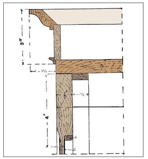
Figure 248—Section of Cornice and Door Rail
Cupboard Pantry Interior
The interior of the cupboard is provided with four shelves, 1 foot, 1 inch wide and ½ inch thick. The top shelf should be fixed near the center of the perforated zinc, so that the two top spaces can be used for fresh meat. The lower shelves can be fitted as needed. The cornice has a small molding to cover the joint with the top (see Figure 248), and is rebated for a frieze panel ⅜ inches thick, surmounted by a cornice molding. The moldings and panel are mitered and keyed at the corners, and strengthened with blocks glued at the angles. When finished, the cornice forms a separate piece from the carcass, so that it can be removed when not in use. The four feet are turned in the lathe, and have dowel ends fitting into the carcass bottom and fixed with wedges. A plinth finish can be adapted if you prefer. This cupboard pantry can be easily converted to a wardrobe if desired by removing the zinc panel and inserting a bevel panel corresponding with the lower one, so that it is desirable to finish the interior neatly.

Figures 249 and Figures 250—Back and Side Elevations of a Basic Kitchen Chair

Figures 251 and Figures 252—Side and Front Elevations of Gate-legged Table
Gate-Legged Kitchen Table
Figures 251 to 254 illustrate a gate-legged kitchen table which, when closed, is 2 feet, 6 inches wide by 4 feet, 4 inches long. The leading points in the making are as follow: The legs and rails should be planed up square to sizes, and the legs set out for mortising. The mortises for the lower rails are of a simple character, the tenons being stubbed inches. For the long top rails the mortises and tenons at one end should be as shown at A (Figure 255) and at the other end as shown at B (Figure 256). Each end of the top rail c (Figure 254) is of the form shown at c (Figure 255). The two rails F (Figure 254) for the drawer have the joints illustrated at D and E (Figure 256), the upper rail being dovetailed in the top of the legs. The two gate legs and their rails are stubmortised and tenoned together. Figures 256 and 258 show how the gate-leg stile is jointed to rails. After the joints are made the whole of the framing should be carefully fitted, and the joints numbered; then the framing should be separated, and the internal parts smoothed off. After you glue and fit the joints, cramp them in position until the glue is dry; odd strips of wood, with a block nailed on each end and a wedge inserted, may be used for this purpose. The top, including the flaps, should be formed of 1½-inch boards, ploughed, tongued, grooved, and glued together. The top and flaps should be planed off true, and the top secured to the rails of the framing by 2½-inch screws driven obliquely from the inside of the rails. The flaps may be attached to the top by 2½-inch wrought-iron back-flap hinges as shown in Figure 253. The top and flaps should be strengthened by 2-inch by 1-inch thick fillets, which are screwed on as indicated at Figures 252 and 253. The stiles of the gate legs should be fixed at the bottom end by a pin working in a socket (Figure 258), the upper end being secured by a screw sunk through the top rail as in Figure 257. As the depth of the side rails will not be enough to fix the runners of the drawer, pieces G (Figure 251 and 254) should be added, and to these two runners can be fixed, and also a cross rail; see H and K (Figure 254). The drawer front should be carefully fitted between the rails and legs, and the sides and back prepared, the back being made wide enough to extend only as far as the plough groove to receive the bottom. The dovetailing can then be set out and made. After this the plough grooves for the bottom should be made. Next some ½-inch boards should be glued up for the bottom, the edges being chamfered to fit into the plough grooves. To secure the bottom it should be nailed into the lower edge of the back, and have strips underneath fixed to the bottom and the sides, these being secured with glue and planed off flush. A knob or handle should be provided and fixed to the front of the drawer.

Figure 253—Underneath Plan of Gate-legged Table

Figure 254—Gate-legged Table Framing
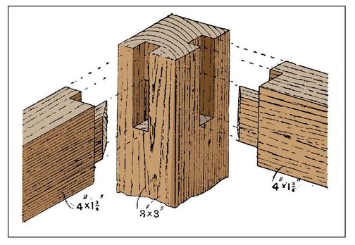
Figure 255—Joint of Top Rails and Leg
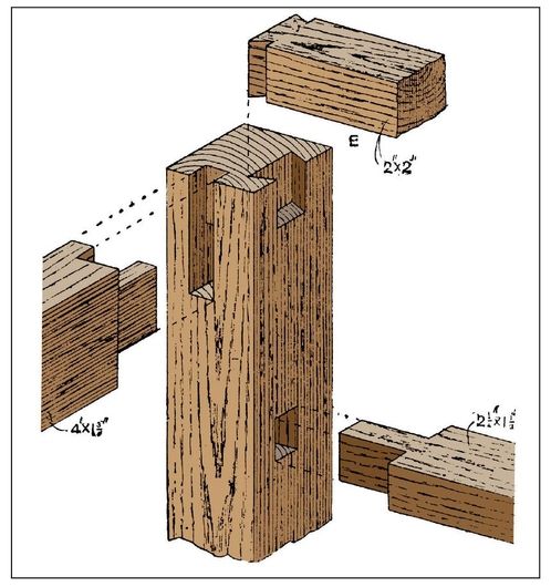
Figure 256—Joint of Rails and Leg at Drawer End

Figure 257—Jointing Gate Leg Stile and Rail

Figure 258—Pin and Socket of Gate Leg Stile and Rail

Figures 259 and Figures 260—Side and End Elevations of Table with Turned Legs
