Bedroom Furniture
Shaving Cabinet
The shaving cabinet illustrated in Figure 261 is arranged so that when you open the doors the light is reflected on each side of the face. You should begin by making the back of the cabinet. It is of ½-inch material, 2 feet, 7 inches by 2 feet, 5 inches, and is either jointed up, as shown in section by Figure 262, or framed, a ¼-inch board forming its center. Cut it out with a bow-saw; the ornamental panels at the top have the outlines cut in about ⅛ inch, the centers being beveled down and punched with the point of a wire nail. The top and bottom boards at the back are ½ inch thick and 2 feet, 6½ inches by 7½ inches The ends form an angle of 45° with the back. The front edge has a length of 1 foot, 3½ inches These boards are 1 foot apart, and are fixed with screws through the back as at a (Figure 263). Frame up the front 1 foot, 3 inches by 1 foot, the rails and stiles being 1¼ inches by ¾ inch, rebated for the glass, and the back edge of the stiles being beveled off at an angle of 67.5°. Cut and fit the brackets as shown in Figure 262. They are glued and screwed through the bottom board and back. Get out the ornamental rails at the top and bottom, miter them, and glue and brad them in place, ½ inch within each edge, and they will then cover up the screws used to secure the front, as at c (Figure 263). Fasten a slip cut to the section of B in each angle at the back; with these slips the doors will come flush. Frame the doors 1 foot by 9⅛ inches of similar section to the front, with the hinge stile beveled to 67.5°, and hand the door in place. This can be fitted either with locks or with hanging handles and catches. Stain and polish, or otherwise finish to your taste, and, finally, insert the mirrors. These should be securely wedged like at D (Figure 263), and covered at the back with thin wood to protect them from scratches.

Figure 261—General View of Shaving Cabinet.

Figure 262—Vertical Section of Shaving Cabinet

Figure 263—Joints of Shaving Cabinet
Boot and Shoe Rack
Figures 264 and 265 show a rack for boots, shoes, and slippers, which you will find useful in almost any part of your house. The rack can be made of ¾-inch yellow pine or sound red deal, and requires two ends, 2 feet, 9 inches by 11 inches by ¾ inch; one top, 4 feet by 11¾ inches by ¾ inch two braces, 3 feet, 6 inches by 3 inches by ½ inch; six rails for shelves, 3 feet, 7 inches by 2 inches by 1 inch; and one molding, 6 feet by 1½ inches by ⅞ inch. First prepare the rails, then plane them square, and take off the sharp corner to form a slight chamfer. Shoulder and tenon each end ready for the ends, which can then be prepared with the mortises. Space them out as shown in Figure 266, the top two rails for children’s boots and slippers. After you cut the mortises, gently drive on the ends and wedge the rail tenons. Across the back, screw two braces B (Figure 266), and then screw on the top from the under-side. Make sure to gouge the ends and braces for the screws. At the front, immediately below the top, place a  -inch diameter iron rod I R (Figure 266) suspended by brass hooks, on which to fix a curtain c (Figures 264 and 266) to cover the boots. The finishing molding along the top can be fixed next, and the rack is then often ready for painting, or staining and varnishing. Rails are preferable to solid shelves, as they admit of a free current of air to dry the soles of the boots.

Figures 264 and Figures 265—Elevations of Boot and Shoe Rack
Bed Rest
For the bed rest illustrated by Figure 267 the following materials will be required: For the frame A (Figure 267) two pieces 2 feet, 1 inch by 3 inches by 1 inch, planed to 2¾ inches by ⅞ inch. For the frame B, two pieces 1 foot, 4½ inches, planed to 1¾ inches by 1⅛ inches. For the frame c, two pieces 10½ inches by 1¾ inches by 1¼ inches, planed to 1½ inches by 1 inch; and one piece 11½ inches by 1¾ inches by 1¼ inches, planed to 1½ inches by 1 inch. There will also be required between 5 yd. and 6 yd. of webbing, one pair of 1¼-inches back flaps, some ¾-inch screws, and two coach-screws, 3 inches by ¼ inch. The wood must first be planed to true. Begin by planing true the face side and face edge of each piece of wood, afterwards gauging to the several widths and thickness, taking care that in each measurement the gauge is set quite  inch full to allow for smoothing off when glued up. When this is true, lay it on the bench, face up, and as the other pieces are planed lay them on the prepared piece, and if each piece does not lie perfectly flat, plane off the part where it touches, that being the highest part. The face edge of each piece can be done in a similar manner. To test with the eye alone, hold up a piece of wood to your line of sight, then slowly turn up the further edge into your line of sight. Notice which corner comes into view first—that will be the highest part. Plane this side down, and the opposite corner of the diagonal. This is because if one corner curls up ⅛ inch, taking
  inch off the opposite corner will make it equally true and the material will hold thicker that if ⅛ inch was planed off one corner. Having planed all the material on the face sides and edges, set the gauge for the width. As each piece is gauged, plane down to the line, taking care that the edge is exactly square before the line is reached; if two gauges are to hand, then the other gauge can be set to the thickness, and the planing of each piece; plan down to the gauge line on each edge, testing for level by placing the back edge of the try-square across the grain.
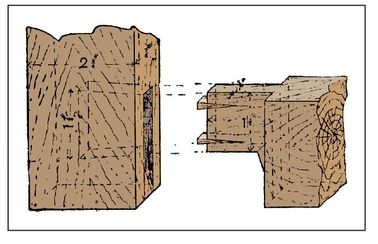
Figure 268—Joint at Corner of Bed Rest Frame

Figure 266—General Sectional View of Boot Rack
Setting out Bed Rest
Now proceed to set out, remembering that in setting out work the face sides and face edges must always pair. For example, take the frame marked A (Figure 267). Take one of the sides, 2 feet, 1 inch long, 2¾ inches by ⅞ inch, and, keeping the face side to the worker and the face edge uppermost, find the center of length; mark off 1 foot (half the height) on each side of this, and square lines across the edge. Then from these lines mark 2¾ inches inwards, being the width of rail at top and bottom of frame, and set out 1⅝ inches width of tenon. Note that the tenon does not go through, only entering 1⅝ inches, which is quite sufficient, the joint being fastened by fox-wedging, which is here shown by Figure 268, but which has already been described. Thus, setting-out lines will only be needed on the face edge. Having set out one side of frame a, take the other side and place it beside the one set out, so that the two sides pair—that is, both face sides are outside and both face edges uppermost. Having squared lines across, set the mortise gauge to the chisel that is nearest one-third the thickness of material, adjusting the one teeth of the mortise gauge so that the chisel just rests comfortably between the points of the teeth, then set the gauge head so that the teeth are exactly in the center, trying first one side and then the other by pricking in the points of the teeth until the points coincide; then tighten up, and holding the stock of the gauge close to the face side, mark the mortises and continue gauge lines for the haunching, running the lines on to the end. Next proceed to set out top and bottom rail of frame A (Figure 267). Take one rail, find the center of its length, and set off half-width of frame less 2¾ inches (width of stile) on each side of center. Square all these lines, taking great care, for it is very important that these, being shoulder lines, should be marked true. Note that the try-square should always be applied to either a face side or face edge. The lines must next be squared to the other rail, it having been first noted in placing the rails together that they pair. then with the mortise gauge mark the tenons all round the end from shoulder to shoulder, Now set out frame b (Figure 267). The material should be ½ inch longer than the finished lengths. Set out one side, starting ¼ inch from one end, and marking off 1 foot, 4 inches, thus leaving a little waste to be sawn off, and enabling a square end to be cut, which can also be shot just before the gluing together. From the first line set off 2 inches (Figure 269). On the face side of one of the 1-foot, 6-inches pieces, commencing ¾ inch from the rail end, set out successively six spaces of 1½ inches each; place the other side so that they pair. Square lines across the two pieces be means of the try-square; you should also square down each edge a little way, and with a marking gauge set to ¼ inch just make a mark on the line; mark the slope with a striking knife, using the edge of the try-square as a straight-edge; then set out the rails 9 ½ inches between shoulders, the tenons 1 inch longer, prepared for fox-wedging, as in frame A. Frame c (Figure 267) comes next, taking one side and proceeding to set it out as in the case of frame B. For dimensions of c, see Figure 270. Note that one end of frame C is semicircular, and that at the center of this portion a  inch hole must be bored through each piece (see D D, Figure 270), so as to enable the coach-screw (the head of which is shown in Figure 271) to pass through for the purpose of hanging frame C to frame A, and allowing it to hinge easily. The other ends of the frame c must be cut at an angle of 45°, to obtain which it is not necessary to have a bevel, for if the thickness of the stuff is set off from the end and a line joined diagonally from this point to the top edge, the angle will be 45°. The cross-rail is set out similarly to frame B; it is 9 ½ inches between the shoulders, and the tenons are 1 inch longer. The setting-out is not complete.

Figure 267—Bed Rest

Figure 269—Horizontal Frame of Bed Rest

Figure 270—Bed Rest Strut

Figure 271—Head of Coach-screw

Figures 272 and Figures 273—Side and Back Views of Corner of Bed Rest Frame
Making a Bed Rest
Begin the actual work by mortising the sides for frame a (Figure 267). The mortises are 1 ⅝ inches, and are widest at bottom for fox-wedging (see Figure 268); note also that the haunching (see Figure 268) tapers from nothing at the end to ⅜ inch at the tenon. Great care must be used in mortising, because if the hole is not perpendicular it will cause the frames to twist, as the tenons will follow the holes, and so tend to take the stuff with it. After mortising, cut the tenons, ripping down first, then sawing the shoulders, afterwards marking width of tenons 1⅝ inches from face edges, and the haunched part of tenon ⅜ inch to nothing (see Figure 268). Next make two cuts in each tenon about ¼ inch from the side and 1 inch long, and prepare and insert in each cut a small wedge of the same thickness as the tenon, ¾ inch long, and tapered  inch to nothing, leaving the wedge projecting at the tenon end. On driving or cramping the frame together the wedges are driven in, and the end of each tenon is widened so that, with the glue, it is impossible to pull it out. A hole should now be bored in the center of each face edge of stiles 9 inches from the

Figure 274—Webbing on Bed Rest Frame
bottom, the hole to be a little less than ¼-inch diameter for the coach-screw to fasten in tight when hanging. It is best done before gluing up, for when together it would be found awkward to bore except with a rather large gimlet. Smooth the edges of the frame so as to leave it clean, and the frame is ready for gluing. The frames B and c can be served in a similar manner. In gluing up the frames, be sure the glue is hot. Get the cramp or cramps together before you begin, and make sure the fox-wedges are right. When the frames are glued up, test them with a large square while applying the cramp; a slight movement of the cramp will correct any error. In frame A, if the diagonals are the same length it is square. If an iron cramp is not to hand, a wooden one can be constructed by screwing cleats of wood on a piece of board, 2 inches or 3 inches wide, and allowing for a pair of wood between the frame and the hammer to avoid dents. When the glue is set, the frames can be smoothed over and the fixing together can begin. A pair of 1¼-inch back flaps and ¾-inch screws will be required to hinge frame B to A (see Figures 272 and 273); about half the knuckle of the hinge projects. The drawings will fully explain the position of the hinges. Two coach-screws, 3 inches by ¼ inch, are needed to hang frame c in position in frame A (see Figure 267); these can be turned in with a pair of pincers. The front should now be covered with webbing. The lengths are cut to the dimensions of frame A, about ¾ inch at each end being turned under and fastened by two ¾-inch clout nails at each end. The spaces between webs should be no more than the width of the webbing, as shown in Figure 274, where it will be noticed that the webbing is interlaced; 5 yd. will suffice, though a little more would certainly make the whole a little stiffer. Finish with a light stain and a coat of varnish.


Linen Chest
Deal is the best material probably with which to make the linen chest illustrated by Figure 275. The elevations and inside view of the chest, which is 2 feet, 3 inches high, 4 feet long, and 1 foot 10 inches wide, are represented by Figures 275 to 277. The two uprights at the front corners are strips of 1½-inch material, 2 feet, 3 inches long by 4 inches wide. Figure 278 shows a front and Figure 279 a side view of that to the right hand. In both figures, a denotes where the upper 4 inches is cut away from the front to a depth of ½ inch to receive the end of the upper front rail; while b is a similar cut to take the end of the lower front rail. At c and D are other cuts for the end rails, all being ½ inch deep. A side view of the right-hand back upright is shown by Figure 284. Its length and breadth are those of its fellow at the front, but it is of ¾-inch board only; 1½-inch wood may be used, to make the job stronger, but one half will have to be sawn away as far as e to receive the ends of the back-boards. Below E, where the double thickness is needed to form the leg, a second piece of ¾-inches material should be screwed on. At F and G this upright is cut away ½ inch to receive the ends of the rails. The rails are all of ¾-inches board and 4 inches wide. The front ones are 4 feet long. The ends of these are cut away behind for a distance of 4 inches and to the depth of ¼ inch to fit the corresponding cuts in the uprights. To these they are fastened with roundheaded screws, as shown. The stiles are also of ¾-inches material, 1 foot, 4 inches long and 3 inches wide, with the exception of the middle one of the front, which is 4 inches. Their tops and bottoms are halved in front for 1½ inches (See H H, Figure 281), corresponding cuts being made in the rails above and below to receive them. Their front edges, as well as those of the rails against the panels, are chamfered off. The paneling of the front is done with ½-inches board, cut to 1-foot, 7-inch lengths. These reach from the bottom of the lower rail to the middle of the upper one, above which is a longitudinal strip of the same board. This may be seen in Figure 277, which shows the inner side of the chest front. This arrangement will make a neater finish than could be gained by carrying the upright boards to the top. In Figure 277 the position of the stiles is shown by dotted lines, and the joints of the paneling should be set up so that it is covered by them.

Figures 275 and Figures 276—Elevations of Linen Chest
The panels which have been thus made are 1 foot, 1 inch by 7½ inches at sight; and, before leaving them, it will be well to finish them by adding the small ornamental spandrils, one of which is illustrated by Figure 282. These are of ¼-inch board, and the curved edge of each is worked to a hollow molding with the gorge. The length of the end rails is 1 foot, 9½ inches The backs of their ends are cut away ¼ inch deep to fit the openings in the uprights—the front end for 1 inch and the back end for 1½ inches The end of the chest (Figure 276) has a 3-inches stile, and is paneled like the front. The back is of ¾-inches boarding, the pieces being 4 feet long and (together) 1 foot, 9 inches wide. At the corners, openings will have to be cut, 4 inches by ½ inch, to admit the ends of the rails. The back-boards are screwed to the uprights, and should also be doweled together. For the bottom ½-inches matchboarding will be best, the pieces being 4 feet long and (together) 1 foot, 10 inches wide. Openings are cut at the corners, 4 inches by 1½ inches, to admit the uprights. These boards are screwed to the lower end rails, also to the lower front rail and to the back-board. For their further support, three ledgers (L L, L, Figure 277), 2 inches by 1½ inches, are placed beneath them and screwed to the back and front rail. The ledgers are placed in line with the middle of the stiles.

Figure 277—Inside View of Chest Front

Figures 278 and Figures 279—Front Corner Upright of Linen Chest Figure 280—Back Corner Upright Figure 281—Front Middle Stile

Figure 282—Spandril for Linen Chest Panels

Figure 283—Oak Bedstead
Linen Chest Base-boards, and Lids
You may prefer to add to the chest the ornamental base-boards and moldings shown in Figures 275 and 276, running along the front and ends. These boards are ¾ inch thick and 4 inches wide. The front one is 4 feet, 1½ inches long; those at the ends are 1 foot, 10¾ inches long. They are mitered where they meet at the corners, and their lower edges are so shaped as to hide the ends of the ledgers Their tops overlap the lower rails 1 inch, and they are screwed to the uprights. Place a strip of molding on these, ¾ inches square, with its front edges simply rounded off. These strips, like the boards below, are mitered at the corners; the front strip is 4 feet, 3 inches long, the end strips 1 foot, 11½ inches. The lid is made of ¾-inch boards, 4 feet, 6 inches long and (together) 2 feet wide. These boards are screwed down to four ledgers, two of which appear in Figures 275 and 276; the others are within the chest, and are placed at equal distances from the outer ones and from each other. As a prop for the lid, have a lath about 1 foot, 4 inches long, working on a screw driven into the inner side of one of the end rails near the front. The chest may be stained to a dark oak color.
Oak Bedstead
Figure 283 shows a beautiful oak bedstead. Leading dimensions are given on Figure 284 and Figure 285, but these dimensions can be varied to your own requirements. Alternative methods of connecting the sides to the foot and head as shown, Figures 286 and 287 illustrating the old bed-screw method of connecting by means of nuts and bolts. In this case a hole A (Figure 286) is bored from the end of the tenon longitudinally in the rail; a mortise is made from the inside of the rail, and a nut B (Figure 287) is inserted, the bolt-head being hidden by the turned wooden button c. A method that is not being generally used is illustrated in Figure 289, the principle being that used on iron bedsteads. A dovetail piece with flanges is screwed to the post, the flanges being let in, and a corresponding dovetail socket piece is fitted and screwed to each end of the rails. The illustration shows the construction fully. The pieces of timber having been cut to their several sizes, each should be planed to finished dimensions. Then the posts and rails should be set out and the mortising and tenoning done. The forms of joints for connecting the stiles and rails of the head and foot are clearly shown at D and E (Figure 288), and the top rails of the head and foot are curved for a better appearance. The curved top rail has a stub-tenon at each end to enter corresponding mortises in each post. The stiles and rails are ploughed to receive a panel, which is shown in Figure 286 and Figure 288, with splayed margins. Cut an oval-sectioned piece F (Figure 288) to proper sweep and sink out the underside to fit on to the curved rail, the posts being recessed so as to receive the ends of the capping. After you fit the joints properly, the posts, rails, and stiles need to be stopchamfered and the tops and bottoms of the posts worked to shape. The joints of the head and foot framings can then be glued together, and when the glue is dry the stiles and rails can be smoothed off. Then the top and bottom rails and stiles are ready to be fit into the posts, which can also be glued together. Four castors should be fixed on the bottom of each post to complete the bedstead.

Figure 284 and Figure 285—Side and End Elevations of Oak Bedstead

Figure 286—Part of Bedstead Post and Panel

Figure 287—Bed-screw Joint

Figure 288—Jointing Bedstead Framework

Figures 289—Metal Dovetail for Bed Rails
Framework of Chest of Drawers
The chest of drawers illustrated by Figure 290 is 4 feet wide, 4 feet, 6 inches high, and 2 feet deep outside. The two sides A, 1¼ inches thick, 1 foot, 10¾ inches wide, and 3 feet, 11⅛ inches high, support the top B, which is 1½ inches thick, 2 feet wide, and 4 feet long, the grooves being ½ inch deep. Two inner pieces D, 1 foot, 10 ¼ inches wide and 3 feet, 5 ¼ inches long, rest on piece c (see Figure 291 and Figure 292). The top piece F and the two lower partitions G are 5 ½ inches wide and 3 feet, 5 ¼ inches long, the shorter partitions H being 5 ½ inches wide and 10½ inches long. The partition J is 1 foot, 4 ¾ inches wide and 3 feet, 5 ¼ inches long, and the vertical partitions K are 1 foot, ¾ inch deep by 1 foot, 4 ¾ inches long, cut to the shape shown by Figure 293, to rest in ⅜-inch grooves in the pieces B, F, and J. Cut all the partitions, including F and bottom E, as shown in Figure 294, and rest, as shown in Figure 291, in ⅜-inch grooves in the partitions D and K, are put in at each side of the drawer spaces for the drawers to run on (see Figures 292 and 295). A ¼-inch boarding separates the drawers, as seen by the black lines in Figure 292. The plinth is 2½ inches thick and 5 inches deep, and should be cut out to receive the bottom and sides, as shown. The whole is raised slightly from the ground by means of buttons, 1 inch thick, screwed to the plinth. The framework should be strengthened where necessary by triangular blocks.

Figure 290—Chest of Drawers

Figures 291 and 292—Longitudinal and Cross Sections of Chest of Drawers

Figures 293—Vertical Partition for Chest of Drawers

Figures 294—Horizontal Partition for Chest of Drawers
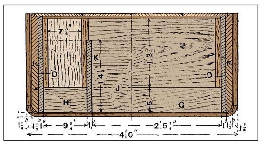
Figure 295—Horizontal Section of Chest of Drawers

Figures 296 and 297—Drawer Details
The Drawers
Fit the drawers together as shown in Figures 296 and 297, but the bottoms of the long drawers are strengthened with two battens. Make the drawer fronts 1 inch thick, the sides ⅜ inch thick, and the bottom and back ¼ inch thick; the smaller drawers can be made of thinner material. The clear spaces for the drawers are as follows:
- Bottom drawer, 11 inches deep, 3 feet, 4 ½ inches wide, by 1 foot, 9¾ inches

Figures 298 and 299—Section and Elevation of Chest of Drawers and Dressing Glass
- Bonnet drawer, 1 foot, 10¾ inches deep, 1 foot, 7 inches wide, by 1 foot, 7½ inches;
- Four short drawers, 5 inches deep, 9¾ inches wide by 1 foot, 7½ inches
Drawer stops should be fixed on the runners. You can make the handles of either wood or brass. The back should be ½ inch thick, and is strengthened vertically by two battens, and rests in a groove in the top B (see Figure 292). You can make the bottom long drawer deeper than the rest, and, instead of the four small drawers and center bonnet drawer, two short drawers can be put in if you desire. Figure 295 is a section on Y Y (Figure 291).
Chest of Drawers and Dressing Glass
Figure 298 shows the front elevation of a chest of drawers, with a dressing glass and jewel drawer at the top. This chest contains four drawers, one 10 inches deep, one 8 inches deep, and two short drawers 6½ inches deep. The chest measures 3 feet over the gables. Plane and square up the two gables 2 feet, 3½ inches in length by 1 foot, 6 inches in width by ⅞ inch thick. The back edges have to be rebated to receive the back, which consists of ⅝-inch matchboarding. Make the bottom from pine ¾ inch thick and lap-dovetail it to the gable ends. Two pieces A (Figure 299), 3 inches wide by ¾ inch thick, are fixed to the gable ends in the same way as the bottom, the object of one being to allow the back to overlap. The front piece may be of pine, with a thin slip of walnut glued to the edge. The two fore-edges B are also fixed to the gables by grooving the latter to form a dovetail (Figure 230). The fore-edges are slid in from the back. Stop the grooves at the front, and rebate the fore-edges to bring them flush there.

Figure 230—Dovetail Joint in Gable
Bedroom Bookshelves
Figure 231 shows the front view and Figure 232 the side elevation of a bookshelf which may stand on a table or be hung on the wall. The drawers are of the usual pattern and make. A wooden back would strengthen the bookshelf, but for ordinary use the ornamental top A and the piece of backing B behind the drawers is enough. Figure 233 shows a larger and highly ornamented set of small shelves with lockers beneath. The shelves and sides can be made of ⅝-inch deal, the outer frame being 3 feet, 4 inches by 2 feet, 4 inches by 6 inches deep, and the pieces may be screwed together for simplicity of construction. The back and top should be of well-seasoned ½-inch boards, glued and clamped up together. The outlines of the ornament at the top (Figure 234) and at the lower ends of the side pieces (Figure 235) should be roughly shaped out, and the orna-ment applied in gesso. The whole of the ornament may be applied this way or it can be carved. The doors of the lockers should be paneled and hinged at the bottom to open downwards. Add a coat of white enamel to finish the work.


Figure 233—Ornamented Bedroom Bookshelf

Figures 234 and Figures 235—Gesso Ornaments for Bookshelf