There were two traditional timber-frame layout systems in use here in America in the past. The older system brought here from Europe was the Scribe Rule. Framers set out timbers in a yard or on a framing floor in the proposed configuration and then custom-mated (or scribed) each of the joints. After a bent was framed, the pieces were marked for future identification and disassembled. The process involved handling each timber a lot as sections were repeatedly assembled and taken apart, but it did facilitate the use of the crooked and waney timber typical of Europe.
Around 1800, a newer system, possibly developed here in America, began to replace the Scribe Rule. Called the Square Rule, this system did not require preassembly. Pieces were prefabricated individually to set dimensions, and timbers such as rafters, braces, and joists became interchangeable. There was much less handling of timber. Edward Shaw wrote in the 1830s about the Square Rule:
Crooked, waney timber poses no problems with the Scribe Rule.
This principle is considered more simple than the Scribe Rule, as it can be applied in many cases with less help and more convenience.
In order to make a good frame of any considerable magnitude, it should be the first care of the master workman (after examining the plan of the frame with care), to make out a proper schedule of the various sizes of the timber. Set down their appropriate marks on the schedule. It is of importance that all mortices, tenons, pin-holes, & c. should be struck with a patron [could mean a pattern, which probably refers to the framing square]; for striking, it should be governed by the appropriate lines. This method has the preference in detached framing: the timber admitting of being framed in different places, and not tried together until its raising.
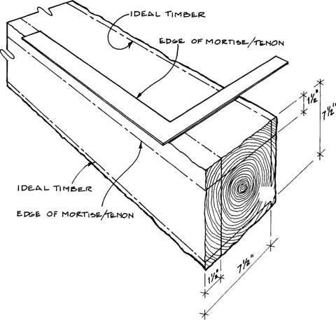
The Square Rule is based on the idea that within every rough timber lies a slightly smaller perfect timber that is straight, square, and consistent in size. All joints are cut to this perfect inner timber. For example, the sawyer calls a timber an 8×8, but the timber may actually measure 7¾ inches by 8⅛ inches. With the Square Rule, you might frame the timber as if it were a perfect 7 inches by 7 inches. It is unnecessary for whole timbers to be exactly sized with this system — only the joints. Rough-hewn or sawn timbers can be framed to make a square, plumb, and level frame. Even the bracing will fit perfectly. Before you begin laying out timbers, you must first determine what dimensions timbers will be framed to, which is related to the maximum variation in your timber. Timbers cut oversize are not a concern. If timbers vary less than ½ inch from what you require, frame them down to the next smaller ½-inch size. Thus, an 8×8 will be framed to 7½ inches by 7½ inches. If the variation is even greater, frame the timbers a whole inch smaller to 7 inches by 7 inches. If an 8-inch timber comes out of the sawmill less than 7 inches, you would be wise to get another sawyer. Remember that all components need not be framed down the same amount, but all timbers of one type should be. For the house from which many of the photos in this chapter are taken, we framed most timbers to the ½-inch smaller size while braces were framed to the next smaller ¼-inch size, and the measured drawings all reflect these adjustments.
The chief tool in timber-frame layout is the framing square. You can use framing squares for more than squaring up your work. Among many other possibilities, they can lay out angle cuts and act as a template to lay out peg holes and joinery. Some squares have tables stamped into them that help you determine board footage, rafter lengths, and even brace lengths. The square that we use today has remained virtually unchanged since the advent of the Square Rule two hundred years ago. It is not a coincidence that the body (or blade) of the square is 2 inches wide and that for softwood frames, a 2-inch tenon, 2 inches from the edge is common, or that the shorter part (or tongue) is 1½ inches wide and that for hardwoods, a 1½-inch tenon 1½ inches from the edge is typical. Thus, framing squares are also templates for laying these tenons out.
When buying a square, look for one that is square (obviously). Numbers should be stamped in rather than painted on. Avoid those with tenths or twelfths graduations. The widths of the blade and tongue should be slightly less than 2 inches and 1½ inches respectively for a pencil or scribe allowance. I prefer steel squares as aluminum versions are easily worn if you use a scribe or knife against them.
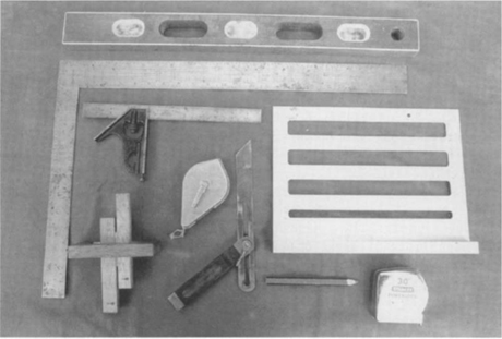
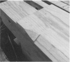
Shown are layout tools: a level, a framing square, a combination square, a marking gauge, a chalkline, a sliding bevel, a Borneman layout guide (see Appendix B), a pencil, and a retractable tape measure.
A combination square is very useful for both laying out and checking joints and with a pencil can be used as a marking gauge. A combination square is not useful for squaring timbers, however, since it’s not long enough to get an accurate reading of squareness on a roughsawn timber.
In the past, measuring was done with a pair of dividers that were walked out along a line. The dividers were set to a specific length with a 2-foot rule. For repetitive measurements, wooden sticks marked with common lengths would be used. Today, timber framers mostly use retractable tape measures. For this project, you will need a 20-foot long or longer tape.
Layout lines can be made with pencil, ink, or the traditional dividers. Pencil and ink show up well during cutting but, unfortunately, in the finished work as well. The marks scratched in by the dividers are less visible and can be left in the finished work. The scratch marks also score the wood prior to boring and cutting and thus save a step. You can also use a marking knife, but these marks show up less well. I often use a medium or hard pencil and draw light lines.
A marking gauge can be used on sawn timbers to lay out joinery. One with two knives can scribe both sides of a mortise or tenon at the same time. Be sure to get one with at least a 4-inch long fence; the small ones designed for planed wood will not work satisfactorily with rough-sawn timber edges.
This section looks at how to use the Square Rule, assuming that you are working with rough-sawn members. Square Rule layout on hewn work is the same in theory but is applied somewhat differently and will be addressed later. Whether you are using rough-sawn or hewn members, however, remember that you must repeat this procedure for each piece.
Begin by checking the dimensions of the piece against the lumber list to be sure it is the right size and length for the member you wish to cut. Set it on the saw-horses. Locate that member on the drawing to see how it is used.
Inspect the piece for defects that might compromise it structurally or visually. Does it have excessive crossgrain, a huge knot cluster, bad shake, or other defects? Is it unattractive? How many faces will be visible in the finished house? If necessary, set it aside.
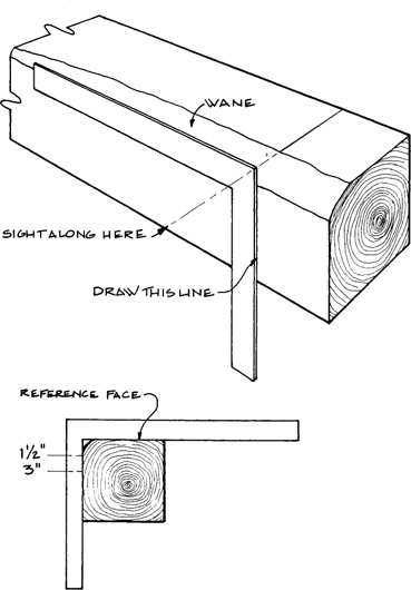
Sight down each of the four edges to determine if they are straight or bowed. If it is to be a spanning member such as a sill, sill girder, floor joist, tie beam, girding beam, girt, or rafter, rotate the timber until the bow (also called a crown in this case) is up. The face that is up should be the right width face — the 8-inch face of the girding beam should be up, for example. This face is our best face. The best face will typically receive flooring, wall sheathing, and roof sheathing; joinery will be flush with and laid out from this face; peg holes will be laid out, bored, and driven from this face; and identification marks will be cut into this face. If you are laying out a brace, post, or plate, put the straightest face up, since it is our best face for these members. Strangely, you may find that in some pieces with a bowed face, the opposite face is straight because timbers bow as each face is sawed.
Next, determine which of the two adjacent faces can serve as a secondary reference face. This secondary face, called the best edge, should be the face that is the closest to being square (use the framing square to check) with the best face and also the straightest. Some joints and peg holes will be laid out from this face, too.
Put an arrow on the best face that points towards the best edge. On the individual joint drawings, the best face is indicated by a blackened arrow that points to the best edge. When the drawings don’t show the best face, a nonblackened arrow on the best edge points towards the adjacent best face.
Check the best face for twist. Put the blade of a square across each end of the face with the tongues hanging down and sight across the squares. If they are not in the same plane, the timber is said to be out of wind. If they are out of wind or if you don’t have a straight or square edge on the timber, either get a new piece or see the section on laying out hand-hewn timbers.
Lay your measuring tape out on the timber and lock it to the proper length. For tenoned members, set it to the shoulder-to-shoulder length of the members, which is the length without tenons. With the Square Rule, this length is simple to figure. Let’s look at an end sill as an example. The building is 18 feet wide exactly. The end sill tenons into a 9-inch sill at each end. Since these 9-inch sills are framed to the next smaller ½-inch size, or 8½ inches, deduct this amount from each end. Thus, our shoulder-to-shoulder length is 18 feet minus 17 inches or 16 feet 7 inches exactly. When we lay out work, this shoulder-to-shoulder length is the one to work with — the overall length is less important. Now, move the tape measure up and down the timber to position the piece to its best advantage, but allow enough extra at the ends for the tenons. Avoid knots and defects at joinery locations if possible. Allow at least 1 inch to square up the ends. Using the drawings, visualize the finished member within the rough timber. Remember that many pieces have a right and left version. You don’t want to make two lefts! When you think you have positioned it properly, lay out the joint nearest the end. It isn’t necessary to lay out every joint before you cut the first one, but it is important to know that one won’t fall on a big knot. Lay out and cut the joint closest to an end first because if you make a mistake, there still may be enough timber length to move down a few inches and recut the joint.
The last thing before you begin cutting is to have a second person, if available, check the layout. If not, check it yourself. Remember to “measure twice and cut once.”
When laying out a timber frame, try to think of it as a three-dimensional puzzle of sorts. You must be able to put those pieces together and visualize the house frame and its parts as you work. S.E. Todd, writing in 1870, put it nicely:
The builder, while laying out a frame, needs to set up a regular “air castle” before his imagination, so that he can perceive how every piece of timber, when he is laying it out, or framing it, will appear after the structure is raised and every part is in its proper place.
Each of the typical joints in the frame will be detailed in drawings and, for a few joints, I will take you step by step through the cutting process. It is extremely important to bear in mind that if there are right-and left-hand members, only one will be illustrated. The version that is not shown is a mirror image of the drawings.
Layout on Hand-Hewn Timbers. When the Square Rule was developed, most or all timbers were hand-hewn rather than sawn. When a timber was laid out, it was lined to the perfect inner timber with chalklines that were snapped on each face to delineate the planes of this inner timber. Since this system is also handy for bowed, twisted, or out-of-square timbers, I will discuss it briefly.
First, put the proposed best or reference face up. Shim the piece until this surface is generally level. If the layout lines from hewing are still visible, shim until these lines are level (or plumb, depending on the piece’s orientation). Hold the tongue (or the blade with 2-inch tenon framing) of the square against the end of the timber flush with the top surface. Sight down this surface of the timber and move the tongue up or down until it appears flush with all the high spots of the uneven surface. Level the tongue of the square as you do this. Now, draw a line on the underside of the tongue. This line represents a plane inside the timber that is generally parallel with the high spots of the surface but lies 1½ inches below it. Turn the square so that the blade is flush with that line and the tongue is generally flush with the secondary reference face. Draw a line along the tongue perpendicular to the first line and 1½ inches away from the high spots of the surface. If the timber is out of square, it may only be flush along one edge of the second face. These two lines represent one side of the mortises or tenons. We need two more lines that represent the perfect inner timber. These lines are drawn with the level the desired distance from the other lines.
After repeating this procedure at the other end of the timber, snap two chalked lines on the top face where the two vertical lines meet the surface. Rotate the timber and repeat on each of the four faces. In general, a chalkline is most accurate when it is snapped vertically, so the plane it will define should be vertical. Since you cannot use a square against the edge of a hewn timber with any accuracy, all joinery is squared up by applying the inside edge of the framing square along the 1½-inch line. To layout a mortise or tenon, the tongue is laid with one edge on the chalked line and a line drawn on both sides of it. Housings are cut to the line that represents the perfect timber.
How to use the framing square and the chalked lines for layout on a “lined timber.”
Chalked lines are typically a 1/16 inch or more in width — certainly more than a sharp pencil or scribe mark — but this need not affect the accuracy of your work if you follow the center of the chalkline when applying the square. If you are working outside, protect the chalked lines from rain.
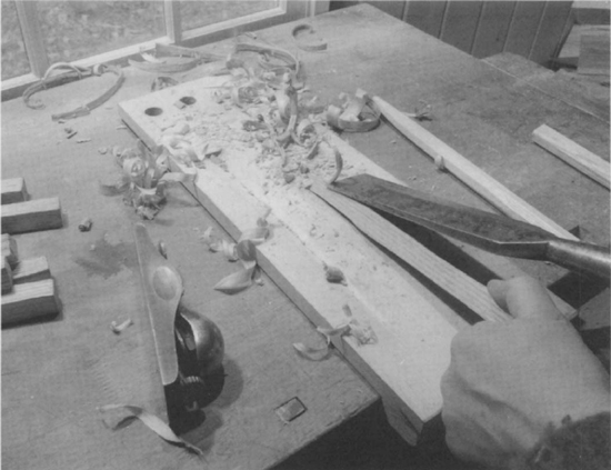
Tools for Cutting Joints. There is always a tendency to think that the old way of doing anything must be harder, and that until modern times people worked extremely hard. When we see old tools in museums, we immediately think of hard, laborious work. Of course, this wasn’t necessarily true. Once you are accustomed to working with hand tools that are properly sharpened and tuned, you will find that they work well and that the work is not hard. Since the craft of timber framing developed using only hand tools, hand tools are still the best way to cut traditional joints. There are many new power tools for timber framing, but too often the joinery is redesigned to enable the joints to be cut with those tools, and then these power tools are not doing traditional joinery. In addition, power tools may seem to make our work easier, but when you consider the extra hours you must work to earn the cash to purchase them you may be increasing your workload. My friend Tim Cahill stated the case eloquently in the October 25, 1981 Berkshire Sampler:
Power tools are fast, but that’s all they are. They are no more accurate than hand tools. Their life support systems have to be toted around from place to place, so they are less convenient. When you cut and drill with electric tools, the noise and the vibration and the power act as a veil between you and your work. There ceases to be any relationship between the builder and the material then, and it’s easier to care a little less.
The frame shown in this book was cut entirely with hand tools from timbers rough-sawn at local sawmills. Hand tools require only a small initial monetary investment when compared to power tools, which is especially important to an owner-builder who will probably build just one house frame. These are the recommended minimum tools for joint cutting:
A 26-inch 8-point crosscut saw. This should be professionally sharpened and set; don’t assume that a new saw is sharp. To keep it sharp, make a wooden slip-on blade guard.
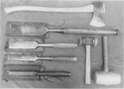
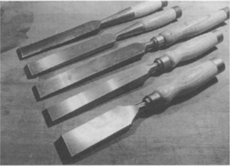
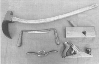
Tools to cut joints (from the top): felling ax, slick, 2-inch chisel, 1½-inch chisel, corner chisel, and a rawhide-faced and a traditional wooden mallet.
An ax for roughing out joints. You can use one with a 32-inch handle, or choke up (place your hands farther up on the handle) on a longer one.
A 1½-inch socket framing chisel. You need a heavy, thick, rugged chisel at least 15 inches long. Socket types are preferred to tang types as the handles last a lot longer and are easier to replace. The chisel blade should preferably measure exactly 1½ inches but not more than 1/16 inch less. If it is exactly 1½ inches, you can use the blade as a gauge to check the width of mortises as you work. The back should have a slight convex sweep lengthwise, because if it is perfectly flat you will not have the proper control as you pare. The cutting edge should also have a slight curve to keep the corners from digging in. I prefer the old framing chisels when I can get them. They are usually stronger and heavier and most old chisels have a hardened steel cutting edge laminated to a mild steel body and socket. The cutting edge stays sharp and the chisel body absorbs the shock of mallet blows without breaking. Turned wooden handles with a ferrule prevent the head from mushrooming and fit into a socket in the chisel rather than over a tang.
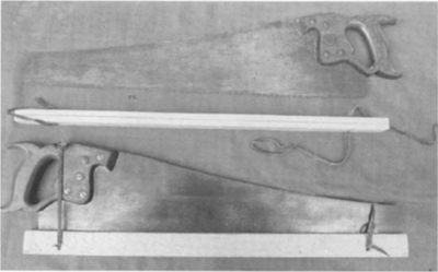
Hand saws should have wooden blade guards to protect the cutting teeth.
Some new chisels that are readily available (from the top): A nineteenth-century chisel (with a new handle) for comparison, a socket framing chisel from Woodcraft Supply, and three Sorby tang-type chisels — extra long, bevel edged, and “Registered.”
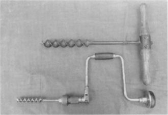
A T-auger (top) and a bit brace.
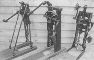
Some boring machines (from the left): Millers Falls, Snell, and “The Boss” Double Eagle.
A mallet for the chisel and pegs. I prefer a 2½-pound rawhide-faced mallet with a cast-iron head. Rawhide mallets make the chisel handles last longer and shock your hands less than some other types. Wooden mallets are fine as well and you can make them as the need arises.
A 1½-inch bit to bore out mortises. The simplest device to bore holes is a T-auger, but it is also the most time consuming. Prior to boring machines, T-augers were the most common boring tools. T-augers fit easily in the tool box, have no moving parts, are inexpensive, and can bore holes at any angle, even overhead. However, the boring machine is by far the best way to bore out mortises. At the time of this writing, antique tool dealers still offer them at prices below that of a good power drill. Most models have depth stops, automatic returns, and can be set to bore perpendicular to the beam’s surface. Unlike most power drills, boring machines have a set screw to keep the bit in the chuck, which is a necessary feature when boring deep holes. You sit or kneel on the base and crank the machine with both hands. Some have adjustable handles for more or less torque, and others have two chucks with different ratios, with the faster ratio presumably for smaller-diameter bits. Some models fold up for storage. I have been working with boring machines for over fourteen years and I think, considering all factors, boring machines are more efficient than power drills.
A 13/16- or ⅞-inch bit for boring peg holes. I use a bit brace to bore peg holes but you can also use a boring machine. Make sure you can bore a hole at least 8 inches deep and 10 inches is better.
The above tools are the minimum needed for this project. If you want to make your work easier, acquire these additional tools:
A chisel with a 2-inch blade. Some of the joints are cut more efficiently with a larger chisel, and another chisel size is useful for making identification marks.
A corner chisel, ¾ to 1 inch wide. Corner chisels can be handy, especially with hardwood mortises.
A 3- to 4-inch wide slick. This is a large, heavy paring tool that is pushed and not struck. Slicks remove lots of wood quickly. Yours should measure 27 to 35 inches long overall and like the chisels should have a slight curve on the back. This curvature allows you to hollow out scarfs and housings to allow for distortion after shrinkage.
A smoothing or rabbet plane, and, possibly, a block plane. A smoothing plane is useful for flattening tenons and smoothing surfaces. The rabbet plane allows you to plane tenons right up against the cheeks.
Shaping tools (clockwise from the top): adz, rabbet plane, smoothing plane, spokeshave, and drawknife.
An adz. This multipurpose tool can rough out joints, scarfs, and smooth roughly hewn timbers. A short-handled adz can work a timber on sawhorses, but the longer ones are used with a timber on the ground or with the vertical faces of a timber on sawhorses. The head needs to be fairly heavy, with the back curved in both directions and a curved cutting edge. Shipwright’s adzes and lipped adzes are lighter than carpenter’s adzes but still usable.
A drawknife. Drawknives quickly remove the bark on waney edges.
A spokeshave. Spokeshaves smooth out waney edges and chamfer timber edges.
A 4- to 6-point 26-inch ripsaw. Depending on the straightness of the grain, it is sometimes faster to ripsaw the sides of a tenon.
A 2-inch auger bit for certain mortises and pockets would be a time-saver.
Dull or improperly sharpened hand tools quickly cause discouragement and frustration. A dull saw rapidly binds or makes it impossible to follow the cutting line. A dull chisel requires more effort and leaves a terrible finish. A dull auger or bit only bores under considerable pressure.
Saws. It is most important that you have properly sharpened and set crosscut and rip saws — there is a lot of sawing in timber framing. The right saw makes your work pleasurable. Have your saws sharpened by a professional first. In most areas there is someone that has a saw sharpening business that uses a filing machine that files all teeth to the same height and angle. These businesses usually also have jigs to set the teeth exactly, and a professional can adjust angles and tooth set for hard- or softwoods and green or dry wood; a good sharpener can even change the number of teeth (or points) per inch. For the small amount sharpeners charge, you can bring them your saws whenever they get dull. However, you may wish to file them yourself a few times in between machine sharpenings. If so, you will need to get a saw vise, files, a jointer, and a handset — see Payson (1988) in Further Reading.
Chisels. Chisels need to be properly tuned. Even new chisels need a little work! When looking for a chisel, look for one that is exactly or slightly less than 1½ or 2 inches wide with the sides parallel. A chisel more than 1/16 inch less than its intended width makes for extra work when cleaning mortises. The back of the chisel should have a gentle convex sweep along its length — approximately 1/16 inch. This sweep creates a pivot that allows you to control the amount you are paring off.
For sharpening, you only need two stones to get an edge that shaves hair: A combination course/fine India stone for general sharpening and a white Arkansas stone for the honing. The stones should be at least 2 inches by 6 inches but 8-inch long stones are better. For honing oil, I use a 1-to-l mix of motor oil and kerosene, which is the least expensive honing oil you can buy. The Japanese water stones are an alternative popular among woodworkers, and they have their advantages and disadvantages. Water is free and readily available, but wipe down tools after sharpening with an oily cloth to keep them from rusting. The coarser Japanese stones do not cut as fast as India stones. The fine stones — 6000-grit and up — are excellent for honing, producing a mirror-finish, razor-sharp edge much quicker than the Arkansas stones. Unfortunately, they are soft and easily gouged by chisel corners.
Before you begin sharpening the bevel, work on the back of the chisel. All pitting, scratches, and other marks should be honed away until at least the first ¼ inch of the back has a mirror finish. Start with the India stone if the back looks badly pitted, then finish honing in a circular motion with the Arkansas stone. Any pits at the tip will create nicks in the cutting edge. It doesn’t hurt if the back is slightly convex across its width, but it should not be concave. Now work on the bevel with the course stone to get the appropriate angle, which is approximately 30 degrees for softwoods and 35 degrees for hardwoods. These angles might vary depending on the specific softness of the wood you work, the hardness of the steel in the cutting edge, and your personal preferences. Use a back-and-forth motion and considerable pressure. I also rock the chisel from side to side as I sharpen to make the bevel slightly convex across its width, creating a curved cutting edge (no more than about 3/32 inch) that keeps the corners of the chisel from digging in. Hold your chisel at a steady angle — use a honing guide if necessary — and grind the bevel until you feel a burr across the whole width of the cutting edge. Use lighter pressure for a few more strokes.
Once you feel the burr, switch to the fine stone. Hold the chisel at a slightly steeper angle (2 or 3 degrees) and only push it forward, lifting on the return stroke. This angle creates a microbevel. Use lighter pressure as you progress. The burr will eventually fall off as you hone, but you can also remove it by backing off: Lay the back of the chisel flat on the stone and pull the chisel toward you once, then wipe the stone and chisel to clear the steel fragments. Continue honing on the bevel with very light pressure until the edge has a mirror-finish microbevel and you can shave the hair on your arm.
Once the edge is sharp, you regularly need to touch it up by honing. After several honings, however, you need to sharpen the bevel again. With good steel and a sheath to protect the edge, you need only sharpen every couple of days. When your chisel stops leaving a smooth finish or has nicks in its edge, it is time to resharpen.
Other Tools. Sharpen plane blades like chisels. I have extra plane irons for my smoothing plane so that when one gets dull I can replace it with a sharp iron. When all of the irons are dull, I sharpen them at once to save setup time. Sharpen slicks like chisels, although you may need to turn the blade at an angle to fit it on a narrow stone. I use a shallower bevel angle for slicks as they aren’t struck with a mallet. The corner chisels are sharpened on one edge at a time. Adjust the angle until only the top edge is touching the stone (the corner of the stone should be sharp, not rounded). Most old corner chisels are a little less than 90 degrees, which keeps the corners from digging in. For bits, I use fine files or small stones for sharpening. A file or India stone works fine when sharpening felling axes and broadaxes. Don’t bother honing as the steel is too soft to hold the edge. Adz heads are taken off and sharpened like chisels except that the cutting edge should curve more convexly than a chisel — about ⅛ inch.
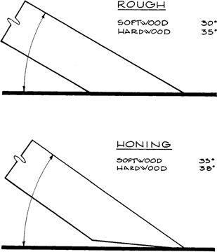
CHISEL SHARPENING ANGLES
This section outlines the process of laying out and cutting individual joints. The instructions for the first few joints are very detailed and take you through all of the steps. I suggest that you begin with these joints before attempting some of the later, more difficult sections. It is also very important to remember that some of the members have both a right- and left-hand version and that only one version is shown; the other version will be its mirror image.
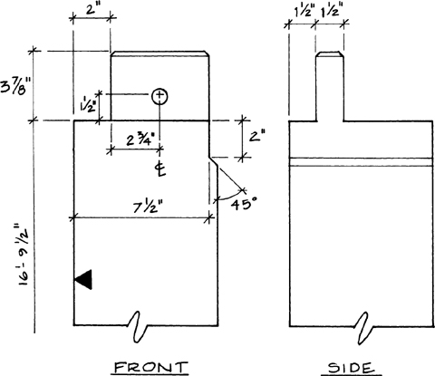
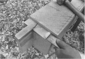
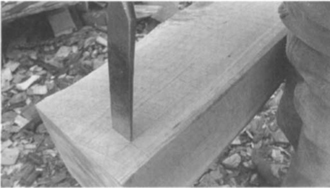
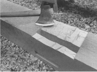
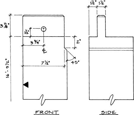
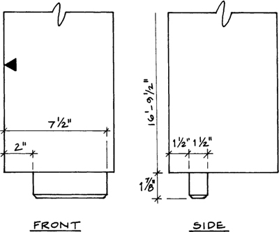
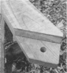
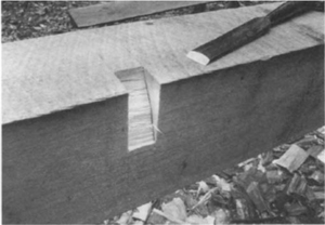
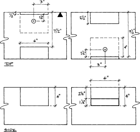
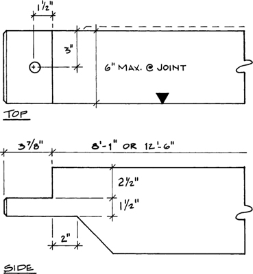
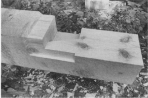
STUB MORTISE
The stub mortise is a very basic joint found where a post bears on the sill — a short tenon on the bottom of the post anchors the post on the sill. The joint is at one end of the piece, the top of the sill is the best or reference face (place that side up), and the exterior side of that face is the best edge. Put an arrow on the best face that points toward the best edge. After positioning the future timber within the piece, mark where your end cut should be. To draw your lines square around a timber, remember one important rule: The blade of the framing square can only be placed against the reference face or best edge (the secondary face). If you try squaring a line around successive sides, the lines probably won’t meet unless the timber is planed to a consistent size. If you only square lines off of reference faces, they will meet, even on tapered pieces. First, draw your line across the top of the piece, then square the line down each side. There is no need to put a line across the bottom side.
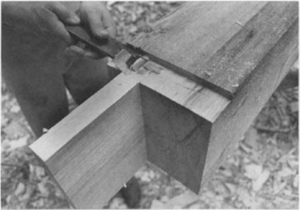
SILL CORNER STUB MORTISE
The large arrow on the reference face points towards the best edge.
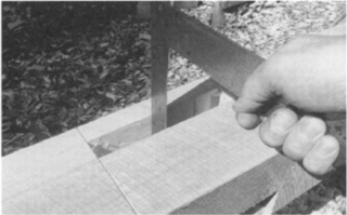
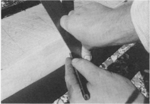
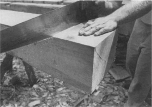
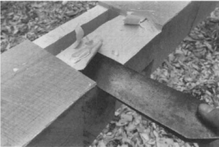
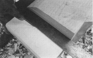
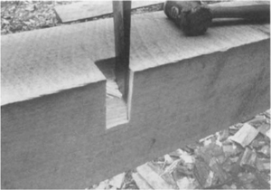
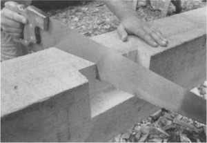
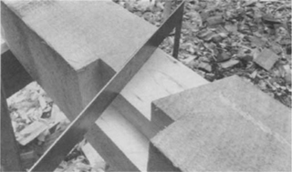
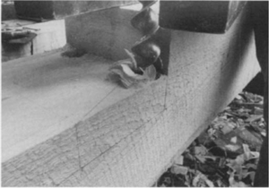
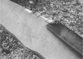
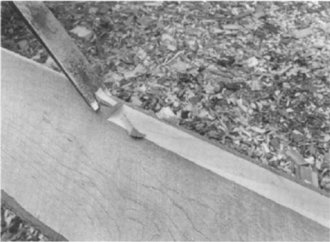
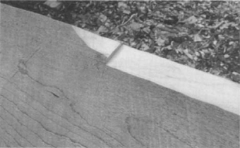
Always begin sawing end cuts on the reference face so that any wandering will be less critical. Saw on the waste side of the line and take half the line with the cut. This may seem difficult to achieve, but it comes quickly with practice. Using your thumb as a guide, start the cut on the top face on the edge opposite you, which is the back edge. Cut only a shallow kerf—about ¼ inch — then bring your thumb to the edge nearest you (the front) and begin working the kerf toward you. Try to keep the saw in the whole kerf but don’t advance any lower on the back face since you can’t see the line there. When you have brought the kerf to the front edge, start down the front face. As you saw down, try to keep the saw in the whole top kerf, too. Continue sawing until the saw blade touches the top back and the bottom front edges — you have cut exactly halfway through on a diagonal. Walk around the timber. From the opposite side, keep your saw at least a couple of inches down in the previous cut and begin sawing down the face nearest you. As you approach the bottom, support the free end to keep it from falling prematurely; you may need to support it with a saw-horse or your upper leg.
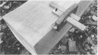
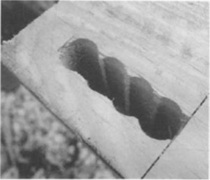
Two lines are scribed off the best edge using a Japanese marking gauge.
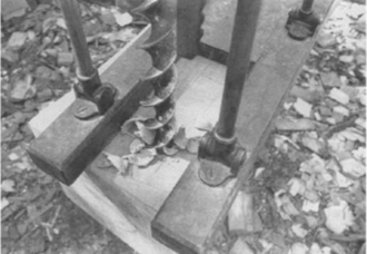
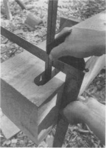
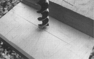
With the boring machine depth stop set for 2 inches, bore the two end holes first, then the two middle ones.
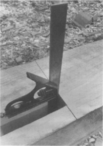
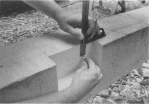
Pare down the sides of the mortise first and check them for plumb off the face with the combination square.
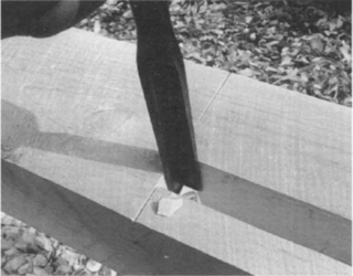
The ends are scored prior to boring with a light tap on the chisel.
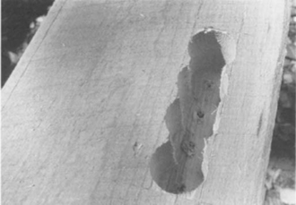
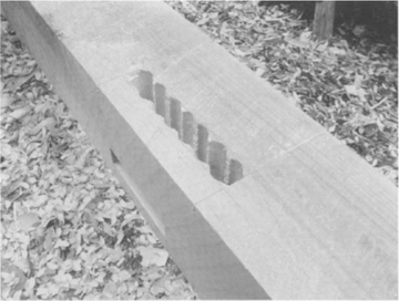
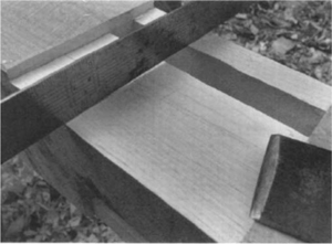
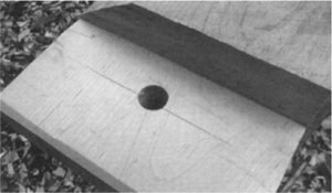
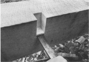
The four holes should look like this.
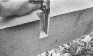
The ends are squared with the corner chisel or the 1½-inch chisel.
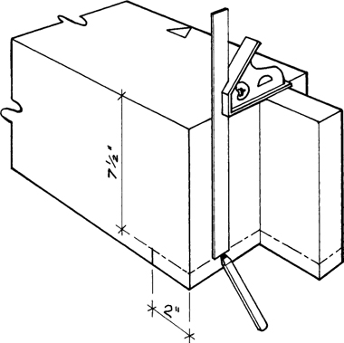
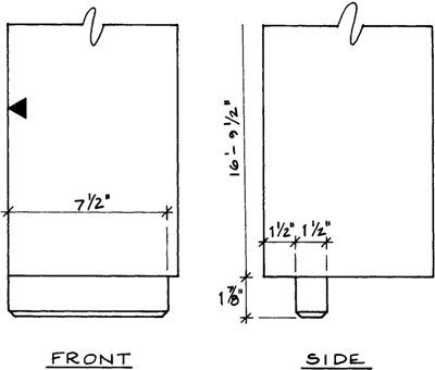
Next, you will lay out the mortise’s position. The 8-inch post is framed to 7½ inches, so measure in that distance from the end of the sill. As the mortise will have a 2-inch relish (in this case, relish is the wood left between the mortise and the end of the timber), measure that out, too. As an alternative, you can use the 2-inch blade of the framing square to both measure and square that line in one step. Scribe the sides of the mortise with a marking gauge, a combination square and pencil, or the 1½-inch tongue of the square applied twice. Finish marking the mortise by scratching diagonal lines from each corner to show what will be removed.
Before boring, the mortise edges need to be scored to prevent the bit from tearing the wood beyond the layout lines. You can use a knife or lightly strike a chisel laid on each edge line with a mallet. Marking gauges score the sides automatically as you scribe the mortise but you still need to do the ends with a chisel or knife.
Bore both ends of the mortise first. If you are using a boring machine, place it over the mortise and sight down the edge of the bit until it lines up with the sides and end of the mortise. Start boring until the bit just starts to cut. If you have a depth stop, set it for 2 inches (or slightly more) of travel. Otherwise, mark a pencil line somewhere on the carriage where you will stop. Some machines have ¼-inch graduations stamped on the uprights. After each end is bored, bore the remainder of the holes, overlapping them if possible. These holes may wander because there is no wood on one side of the hole, but wandering is less of a problem in the middle. Before I begin boring, I determine the number of overlapping holes needed. If there are five holes required, I’ll bore the ends, a middle hole, and then the remaining two. With an odd number of holes, there can be equal wood on either side of the hole to prevent bit wandering.
After boring the mortise, you must clean it up by paring. The sides of the mortise are pared first. Put your chisel into the scored line and push down — the curved remnants are easily pared away. Remember to keep the flat side of the chisel against the wall of the mortise when paring and to keep paring until the mortise sides are perpendicular to the top (reference) surface and the mortise is 1½ inches wide. Check the width by sliding the tongue of the framing square back and forth. Finally, square the corners. You can use the corner chisel if you have one or a 1½-inch chisel and the mallet. Pare the ends until they are square with the top surface, too. Check for squareness using a combination square set for 2 inches.
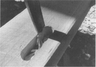
Because stub mortises are not pegged, this mortise is done. The mortise is on a reference face, so there is no housing. You do, however, need to indicate its location with a Roman numeral a few inches away from the mortise, in the center of the timber and across the grain. Refer to the discussion on the numbering of pieces at the end of this chapter.
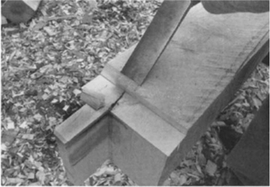
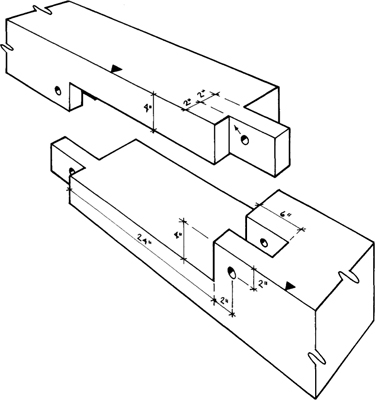
See the measured drawing for the Lap Dovetail Tying Joint shown on pages 114 and 115.
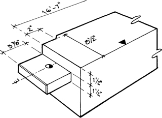
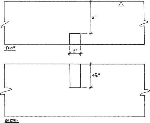
When a mortise is in a nonreference face, it must be housed to the ideal timber, a situation that occurs throughout the frame. This section looks at a mortise in the underside of the plate for an end post. Lay out the mortise as in the previous example, but make measurements on the reference face and bring them around to the mortised face. In addition to the mortise, you must lay out the housing. The 10-inch depth of the plate is framed to 9½ inches at the housing. Set your combination square to 9½ inches and draw a line around the sides and end of the timber. Thus, the plate is reduced to 9½ inches over each post.
At the inside end of the mortise, make a saw cut down to the housing depth. The rest of the mortise is scored as before. The mortise depth is 4 inches beyond the housing, so add the housing depth to the overall depth. Because the housing depth can vary with the actual timber size and even along a timber, check the depth for each mortise. If the timber is exactly 10 inches, it would have a ½-inch housing, so the depth would be set at 4½ inches or a little deeper. When you set the boring machine up to bore on a nonreference face, check to see if that face is reasonably square with the reference face. If it isn’t, shim the machine to compensate. The finished mortise should, of course, be perpendicular to the ideal timber.
After boring, clean up the sides first as before, but note that you cannot check the mortise sides for perpendicularity to the surface because it is not a reference face. Using the combination square and the framing square, you can check the sides off of the reference face. The ends, however, can be checked well enough off the surface. When the mortise is complete, cut out the housing. This is chisel-and-mallet work, although I sometimes rough it out with an ax. Work the edges down to the line, then cut the center. To create a surface that will be flat when the timber has seasoned, you must actually hollow the green timber, which is when the chisel or slick with a slightly curved back is necessary. On white pine, I hollow the shoulder between 1/16 inch and ⅛ inch, but use more for woods with higher shrinkage rates. Without this hollowing, there will be gaps when the timber dries.
To lay out the peg hole, turn the reference face up. Place the tongue of the square flush with the edge of the mortise and draw a line on the opposite side. Locate the center of the peg hole on this line in the middle of the mortise. With a bit brace, bore a peg hole until the bit just breaks through into the mortise. Before continuing, sight it from two directions to be sure it is vertical. Continue boring till the tip barely pokes through the bottom of the timber. Flip the timber over and finish boring out the remaining wafer-thin portion. Sometimes turning the bit backwards helps prevent tearouts.
The edge of the housing is sawn down to the shoulder, which simultaneously scores the ends of the mortise.
Bore four holes to the depth of the mortise plus the depth of the housing, which should be about 4½ inches.
The sides of the mortise can only be checked for plumb off of the reference face — use the combination square and the tongue of the framing square.
The ends can be checked for plumb off of the surface.
The housing should be scooped out towards the middle to allow for shrinkage.
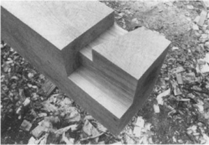
The finished mortise.
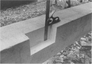
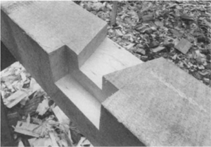
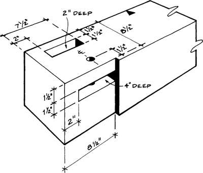
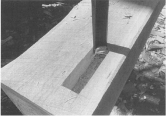
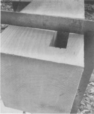
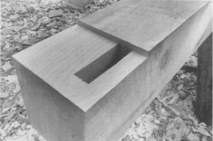
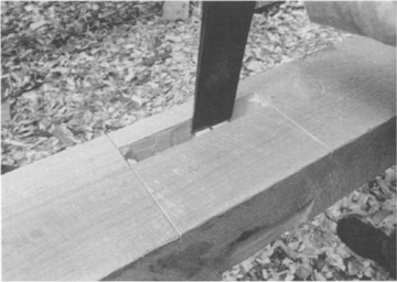
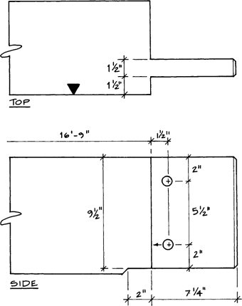
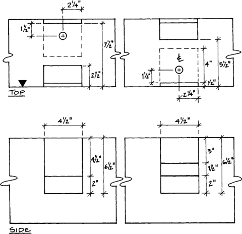
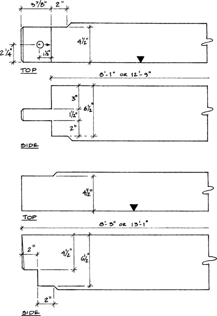
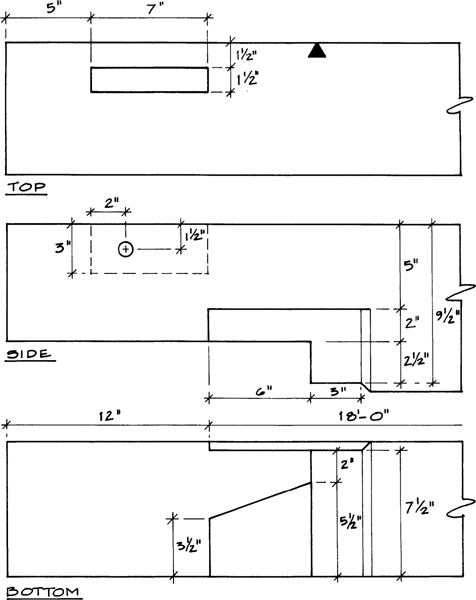
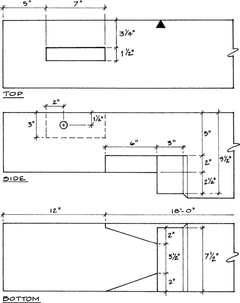
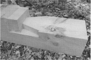
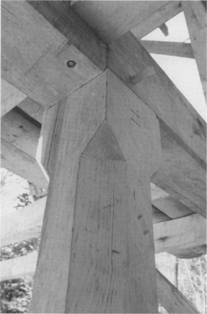
This joint has a through-mortise, and since the tenon enters on a nonreference face, you must house the joint. Since the girding beam is a nominal 10 inches reduced to 9½ inches, the mortise measures 9½ inches. The 8-inch post is framed to 7½ inches at the housing. Lay out on the reference face the 9-foot level of the second floor level. Next, measure down 9½ inches to give you the other end of the mortise. Bring these lines around all four faces of the post. From the best edge, lay out the sides of the mortise as before on the shouldered face and the opposite face since through-mortises are cut halfway from each face.
GIRDING BEAM MORTISE
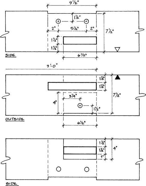
Both ends of the housing are sawn and seven holes are bored halfway through from each face.
On these larger mortises, the slick is more effective for paring than a chisel.
Saw the ends of the mortise down to the housing depth and then score the mortise sides. On the outside reference face, just score the edges. Bore seven holes just past half the total depth from each face. The chisel work is done as with other mortises, but you do need to flip the post over periodically to work the mortise from both sides. The slick works especially well on the sides of this mortise. When you slip the tongue of the square in the finished ideal mortise, you should be able to slide it back and forth with only minor resistance. At the ends, it should touch the line at both the top and bottom faces and be nearly straight in between.
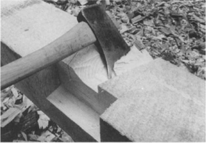
The housing is roughed out quickly with the ax. Bring down the ends first and then split off the sections between. You then use a slick or a chisel to pare to the line. Again, the housing must be hollowed out to allow for shrinkage distortion.
The mortises for the wall girts also occur at this level. On posts 2 and 3, one mortise intersects the through-mortise and the other comes very close to it. It would be wise to place a snug-fitting block in the through-mortise to prevent tearout when boring and chiseling these other mortises.
Check the width of the mortise by sliding the tongue of the framing square in the mortise.
The housing is quickly roughed out with the ax.
The slick is also useful for paring the housing.
The ends are finished with a corner or 1½-inch chisel.
Hollow out the housing toward the middle.
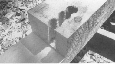
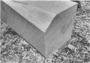
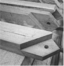
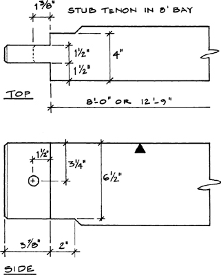
All of this frame’s brace mortises are in nonreference faces, so all will be housed to the ideal timber, a practice that was fairly common in old frames as the housing provided extra bearing. If I am laying out a plate, for example, I cut the post mortises before the brace mortises. Then I simply hook my tape measure on the shoulder edge of the post mortise and measure and mark 3 feet. Then I back up 7 inches for another mark. The 7-inch mortise length accommodates brace stock up to 55/16 inches wide. There is one exception to the 3-foot measure. Though the braces that go from the posts up to the tie beam are the same length and angle as the others, the joinery requires that the post brace mortise is measured 2 feet 7 inches from the shoulder. The tie beam brace mortise is measured out 3 feet 1½ inches. If you study the drawings, it will be evident why this is necessary.
Unlike the other mortises, the brace mortise has a housing on only one side. The mortise measures 1½ inches in width and is 1½ inches from the face. The housing is measured from the reference face and is either 7½ inches for posts or 9½ inches for plates and girding beams. After the sides are scored, I score the ends by sawing down to the shoulder on an angle. Then I bore five holes 3 inches deeper than the housing.
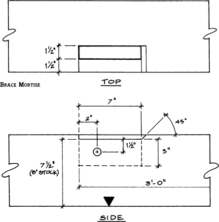
After squaring up the mortise, I bevel the end opposite from the bearing end at a 45-degree angle to provide clearance. The peg hole is easily laid out using the square as shown. The hole is 1½ inches from the edge of the mortise and 2 inches from the bearing end.
The peg hole is located by aligning the outside corner of the framing square against the square end of the mortise; scribe on the inside corner of the framing square.
The housing can only be partially sawn.
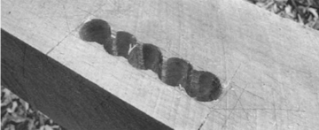
Bore the two ends and center of the mortise first.
The finished brace mortise.
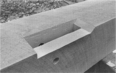
You can see in the photos (see page 98) and drawings that this post top tenon occurs in a waney section of the post, but the wane is no problem. With the reference face up, lay out the 3⅞-inch long tenon. Using a drawknife, remove the bark and smooth the wane till it is flat. To drop the line down the vertical face past the wane, lay the blade of the square against the vertical face so the blade’s edge lies flush with the top surface. Get down and sight across the blade or place a couple of heavy flat objects on the top surface and push the square against them. Now draw the vertical line. Lay your square across the wane and connect the two lines. Next, lay out the tenon on the end and sides of the timber. To measure down a waney edge for tenon layout, lay the edge of the blade on the top surface and mark where the respective marks on the tongue fall on the side of the timber. Connect these marks with the lines on the end of the timber.
INTERMEDIATE POST TOP TENON POSTS (BENTS 2 AND 3)
Saw the shoulder, remembering that you are only sawing on the lines you can see. The waste on either side of the tenon can be split off with a mallet and chisel or an ax. Keep the chisel’s bevel down for control and work your way slowly, splitting off about ⅜-inch chunks at a time. Watch the grain as you go down since if the grain wanders, the split could run below the line. When you are within ⅛ inch of the line, pare with the chisel or slick, working the edges to the line first. If you have a rabbet plane, you can plane the tenon to the line right up to the shoulder. When you have a flat tenon exactly to the line, taper the last 2 inches down about 1/16 inch. The taper won’t affect the quality of the frame but does allow for easy insertion. The base of the tenon should be true, which you can check by applying the tongue of the square and feeling if it is flush with the surface.
Turn the timber over and draw a line that connects the lines on the sides. Saw down this shoulder. Because the waste here is much larger, you can split off chunks more aggressively but you still need to watch the direction of the grain. Pare to the line and again taper the tenon.
The tenon and top of the post must be reduced to the 7½-inch size where the tenon enters the mortise and housing. Set your combination square for 7½ inches and, using a pencil, mark a line all around the tenon and 2 inches down the post. Use the thickness of the blade of the framing square to mark the 2-inch line. Saw down along this line to the ideal timber. Split off the waste and pare to the line. With the chisel’s bevel down and using the mallet, cut back the waste at about 45 degrees to create a bevel between the ideal inner timber and the rough outer timber. Make sure the last couple of inches of tenon on all four sides are tapered about 1/16 inch. The same tenon is used for single- and two-story posts. However, because of joinery conflicts in the sill girders, the basement posts can only have a 3-inch long tenon. If this were a corner post, on the other hand, one extra step would be necessary: Two inches of the tenon must be removed to allow for the relish on the mortise. Lay out this cut from the outside face of the post with the combination square set for 2 inches and then saw and chisel the waste. Taper as with the other sides of the tenon.
The square can be used on a waney edge by aligning the blade flush with the top (reference) surface. It can also be used to measure off of a waney corner by applying it as shown in the lower drawing.
To lay out the 7½-inch post top, set the combination square for 7½ inches and mark all around the timber.
The ends of all the post tenons get a ¼-inch chamfer on the four edges by paring with a chisel held askew, which allows the chisel to slice through more easily. You could also use a plane held askew.
To lay out the peg hole, place the blade of the framing square against the best edge and the tongue on the tenon against the shoulder. Mark a line against the tongue that shows the distance from the shoulder. Find the center of the tenon (3¾ inches from either side) and mark a V there. Since we are drawpinning, bore about ⅛ inch closer to the shoulder, but don’t mark this difference — just eyeball it and bore. When the point pokes through, finish the hole from the other side.
The posts of bents 1 and 4 are similar to the posts of bents 2 and 3 but have 2 inches of the tenon removed to provide relish in the mortise at the end of the plate.
Connect the lines across the wane after you have squared down the side.
The tenon is also connected across the wane.
After the rough chisel work, the rabbet plane can smooth the tenon to the line right against the shoulder. Use the smoothing plane to finish the surface.
The tenon can be checked by applying the tongue of the framing square against the shoulder — the square should be flush with the surface of the timber.
First, saw the side of the post and then chisel down to 7½-inches. The rabbet plane can be used here as well.
Using the mallet and chisel, make a 45-degree bevel.
To lay out the peg hole, align the tongue of the framing square against the shoulder and the blade against the best edge; scribe a line and then mark a V in the center of the tenon.
The peg hole is offset towards the shoulder about ⅛ inch.
The brace and bit bores a clean holes.
POST BOTTOM STUB TENON (BENTS 2 AND 3).
POST BOTTOM STUB TENON (BENTS 1 AND 4)
These tenons are similar to the post top tenons but are shorter because they only serve to locate the post in the sill. They are not pegged — only the tenon is reduced to the 7½-inch dimension as there is no housing on the top of the sill. The corner post stub tenons are cut down 2 inches in width to provide relish in the mortise. Give them a healthy taper and chamfer for easy insertion.
These tenons are identical to the corner post top tenons except that they are framed in 8×9 stock.
SILL CORNER TENON LAYOUT
GIRDING BEAM TENON
This through-tenon is 7¼ inches long and worked much like the corner post top tenons. However, because of its size, you can use the ax to rough it out. For paring, the slick is indispensable here. Taper the last 2 inches or so of the tenon about 1/16 inch. The end of the girding beam and tenon get reduced to 9½ inches where they fit into the post mortise housing.
Because this is an important joint, it receives two peg holes. Lay the square on the tenon and mark a line along the tongue. Place a V-mark 2 inches in from each edge of the tenon.
GIRDING BEAM TENON
Be careful when sawing down to the shoulder — only saw along the two lines you can see. Finish up by sawing from the opposite side.
The ax can quickly rough out the tenon.
The bottom of the beam is brought down to 9½ inches at the joint.
The finished joint with peg holes and identification marks.
SILL GIRDER MORTISE AND TENON.
This joint is similar to the girding beam mortise discussed earlier but it is reduced in two dimensions as it joins the sill. The sill girder is not only reduced at the end to the 9½-inch width, but the depth is reduced to 6 inches. The housing on the sill is 6 inches instead of the full width. This provides bearing so all the weight is not on the tenon.
SILL GIRDER MORTISE AND TENON.
BRACE TENON
Because the braces make the frame plumb, true, and resistant to racking, they are important elements. To many novice framers, making braces work seems like a formidable task. However, I hope to show you that if you use the Square Rule and cut to the line, braces are not difficult. When erected, the frame will be plumb and true. You may also find it useful to refer to the section on rafters that follows for drawings that show how to lay out pitches with a framing square. If you still have difficulty, however, The Steel Square (Siegele 1988) is an excellent reference — see Further Reading.
The length of the diagonal braces is determined from the Pythagorean theorem, which says that the square of the hypotenuse (the long side) of a right triangle is equal to the sum of the squares of the other two sides, which is usually written as A2 + B2 = C2, where C is the hypotenuse. If the sides of our triangle (A and B) are 36 inches long — one of the more common sizes in the past — then our brace length is 50.9117 inches. Round that off to 5015/16 inches. This number and other common brace sizes can be found in the brace tables on many framing squares.
BRACE TENON
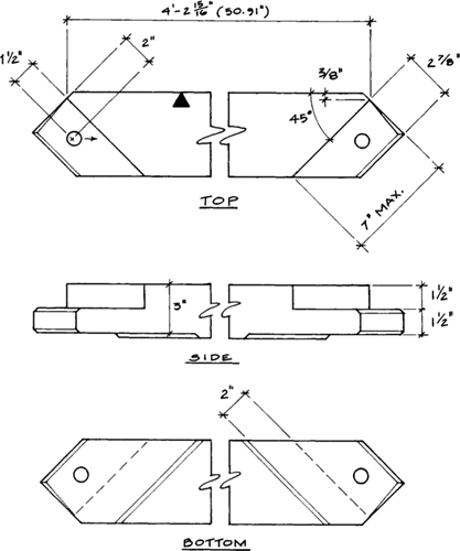
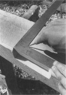
Two braces can be cut from a 10-foot long piece (3¼-inch by 5-inch stock). With the best face up, determine the best edge and make sure the edge is square with the face. Establish a reference line on the top face that is ⅜ inch from the best edge, which gives a ½-inch bearing shoulder that will approximately match our housing. On the other hand, if our housings were about 1 inch deep, then this distance would be ¾ inch instead. Regardless, set out this line with the combination square on a sawn timber or with a snapped chalkline on hewn or curved stock. All the brace angles are 45 degrees, so lay them out with the framing square as a 12-in-12 pitch off the best edge (or chalkline). Then the vertical lines are dropped square.
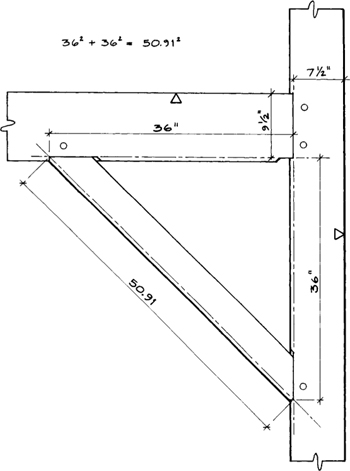
THE MATHEMATICS OF BRACE LAYOUT
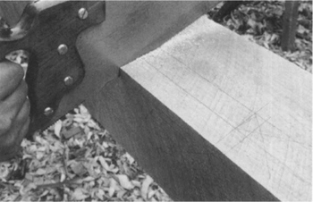
The first cut is the end of the tenon. Then, with the combination square, drop a vertical line on the cut face and then saw the nose or bearing end. Drop a vertical line again. Lay out both sides of the tenon all the way around and a few inches past the joint. Cut the shoulder line down to the tenon. Split off the chunks and pare to the line (the rabbet plane works well here). If the tenon grain is wavy or knotty, you may find it faster to ripsaw the tenon. Turn the brace on edge and saw only the two lines that you can see. Then flip it over and finish the cut. Touch the sides up with the chisel if necessary, then taper the tenon as before. Because it is a barefaced tenon (a shoulder on only one side), the other side merely gets taken down to the tenon. The end of the brace must be reduced to 3 inches thick a few inches back to clear the housing. If only 1/16 inch or ⅛ inch needs to be removed, a plane is more appropriate than a chisel. If it is more than ⅛ inch, saw down to the line and pare it away. Don’t forget to bevel it back as with the other joints. Chamfer all end-grain edges on the tenon.
If the brace stock is over 55/16 inches wide, the piece needs to be brought down some to fit the housing. Since the housing length is 7 inches, measure your shoulder to see if it is smaller. If more, reduce the width with an adz or plane. If it is less, there will be a gap at the nonbearing end of the mortise, but the gap does not affect the integrity of the frame and was standard in old frames.
The peg hole placement is easy. With the tongue of the square against the shoulder and the blade tight against the nose, scribe a line on the tenon. Scribe a V on the line 2 inches from the bearing end. When boring, offset the hole towards the shoulder but make it parallel with the piece, which will pull the joint tight. To lay out the other end of the brace, measure 5015/16 inches from the point of the nose. All braces are interchangeable so there is no need to number them.
After cutting the end off, drop the line of the nose of the brace down the end and make this cut.
Drop the shoulder line down with the combination square.
Split off the waste wood as you would on any tenon and pare or plane to the line.
Chamfer the end grain edges and bore the peg hole.
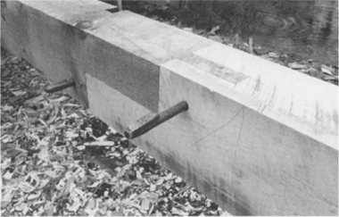
Finished black cherry braces.
When assembled, the brace should be snug at the bearing end. The gap at the far end of the joint is to allow stock of varying widths.
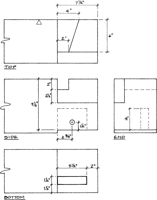
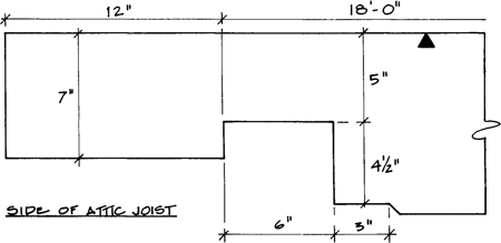
These are pockets that the attic joists merely drop into. Saw the sides of each pocket down to the line as shown. In softwoods, they can then be worked down with a chisel and mallet. In hardwoods, it may be faster to bore the hole. If you are using the chisel, first split out the triangular waste chunk. Then, starting at the top, work the three vertical faces down together. Check with the combination square as you do. When you get to the bottom, work carefully as you do not want to undercut the weight-bearing part of the pocket. To check the bottom, set your combination square for 4½ inches, using the top as a reference.
If you bore these pockets, use a 1½- or 2-inch bit and remember to score the edges of the mortise with a chisel to prevent tearout and to set your depth at about 4¼ inches. You may want to bore before you saw since with some woods the blocks might split out as you bore. The corner chisel effectively works the corners.
ATTIC JOIST POCKET
The pockets are easier to saw if you lay the plate down flat. Saw until you just touch each line.
The triangle of waste wood splits off easily.
Work down the vertical faces but keep square with the top.
The last bit of waste is scored all around from above and then split out from the side.
Set the combination square for 4½ inches and check the depth and squareness of the sides.
FLOOR JOIST POCKET AND MORTISE
The first-floor joist pockets are worked similarly to the attic joist pockets, but because they are larger, boring definitely saves time. Bore two holes — one in each corner — to within ¼ inch of the pocket depth. The large triangular block is split out and the chisel is used as before.
The second-floor joist pockets have a housing of about ½ inch. The pockets in the center bay are also housed for strength even though they are in a reference face. After cutting out the upper portion, lay out the lower housing. For pockets on a nonreference face in the outer bays, drop vertical lines down from the top to locate the housing. For pockets in those bays in a reference face, set your combination square for ½ inch and mark off the face. The housing is sawed and chiseled out.
The tying joist mortises are similar to the previous mortises. After layout, the housing is sawed and the mortise is scored and bored. After the mortise is finished, the housing is chiseled out. Check it for square off the top (reference) face.

FIRST-FLOOR JOIST POCKET (END SILLS, 8×9 STOCK)
FIRST-FLOOR JOIST POCKET (IMTERMEDIATE SILL, 8×10 STOCK)
SECOND-FLOOR JOIST POCKET (GIRDING BEAM, 8×10 STOCK)
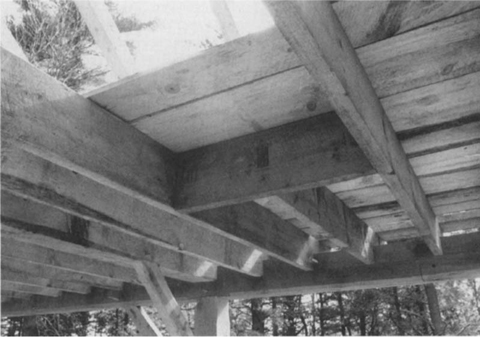
Drop-in joists.
The drop-in joists are fairly simple. Square them to length and lay out the ends. You can choose to saw them out entirely or to saw and chisel them. Traditionally, the joists were not sawed at all. They were roughed out with an ax while upside down in their pockets. They were adzed flush with the sill and the bevel was dressed with the adz. If they are thicker than 6 inches, the joists have to be planed down to fit. Tying joists are similar to drop-in joists but have their tops cut to create a barefaced tenon, which has a shoulder on only one side.
FIRST-FLOOR DROP-IN JOIST
Tying joist.
FIRST-FLOOR TYING JOIST
SECOND-FLOOR JOIST
The drop-in joists are relatively easy. The whole joist end is housed into the girding beam, so reduce it to 4½ inches wide by 6½ inches high at the end. The tying joist tenon is cut like other tenons.
In effect, the girts in this frame are floor joists against the outside wall, although they do join to the posts. The two girts in the center bay have stub tenons — in this case only 1⅜ inches long — and are not housed into the posts. Only the tenon has to be reduced to 6½ inches, but you might reduce the whole end to match the other girts.
SECOND-FLOOR GIRT
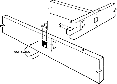
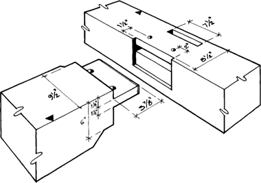
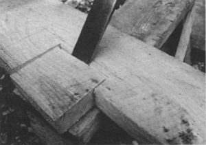
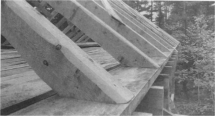
LAP DOVETAIL TYING JOINT IN PLATE
LAP DOVETAIL (BENTS 1 AND 4)
In order to provide relish on the ends of the plate, the end tying joints are different from the middle ones, but both are worked similarly. Cut the housing first, like it was a joist pocket. You can bore the housing or rough it out with an ax by standing on the plate.
Lay out the 2-inch deep dovetail on the side of the housing. The dovetail is sawed on either side and the middle is chopped out with the ax. Finish by paring to create a hollow to allow for shrinkage distortion.
The housing is first cut out by sawing and chiseling. Be sure to check the accuracy of the depth and the squareness of your cut.
Saw down the sides of the dovetail.
Check the depth by laying the blade of the square to see if it is flush.
With the combination square set for 2 inches, draw the bottom of the lap dovetail.
Remove the waste with the ax and pare to the lines.
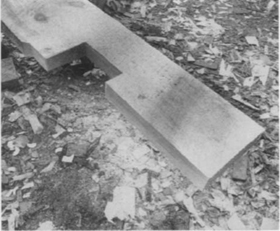
FINISHED LAP DOVETAILS
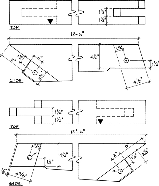
TIE BEAM
These tie beams have considerable work in them and should be attempted only after you have gained experience on the other joints. There are two different dovetail designs, one for the ends and the other for the interior beams. Though the layout is a bit different, the procedure for cutting them is basically the same.
After squaring the end, cut out the 18-inch long lap portion by sawing down to the line at one or more locations. An ax can remove this bulk of wood quickly, but be sure the end is supported underneath by a sawhorse because the ax blows might otherwise cause a fracture. Score and split off chunks as with hewing. When you have split to within ¼ inch of the line, finish with a slick and a plane. This surface gets hollowed out about ⅛ inch.
Lay out the dovetail as shown. Saw down diagonally as with joist pockets. You can even bore out the corners if it saves you time. Remember that this joint needs careful chisel work — this joint must be cut to close tolerances or it won’t go together. When the dovetail is complete, the two nonreference sides must be brought down to the ideal timber size and beveled back. The rafter mortise on the top side is straightforward. There is no housing because it enters a reference face.
The dovetails are sawn first.
The last step is bringing the tie beam down in thickness where it fits in the plate. Here is a finished tie beam from bent 2 or 3.
The dovetails can be bored if it makes the work easier.
An end tie beam for bents 1 or 4.
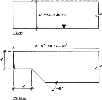
Scarf joints that fit tight always gain the respect of onlookers. They are not that difficult to master if you follow these guidelines. When you lay out a plate or sill, put the scarf in the end that is the strongest and least waney and has the clearest grain, which is usually the butt or stump end. Be sure to pick the straightest edge for a reference, which can be hard with long timbers since they sometimes take a slight turn at the end. Lay out both upper and lower halves of the scarf from the top (reference face) and outside (best edge). That way, when the parts are assembled, they will be flush on those two faces. Inside faces may not be flush if the timber sizes differ, but they can be planed flush if you don’t like the way the variation looks.
SILL SCARF (8×9 STOCK)
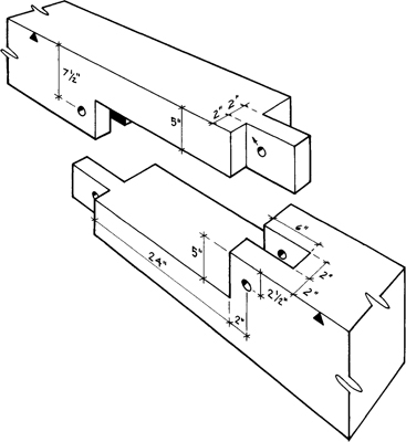
PLATE SCARF (8×10 STOCK)
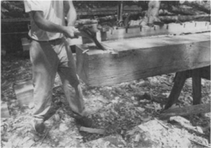
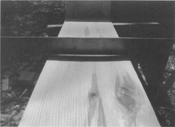
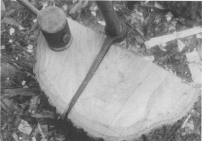
Regardless, measure carefully and keep your pencil lines thin. Square up the end first before laying out the scarf. Mark the waste, which on one piece is the upper half and on the other piece is the lower half. Cut down to the 30-inch long half-lap. If the grain is knotty or wavy, saw at intervals of 4 inches. You could use a coarse fast-cutting crosscut saw here, but stay ⅛ inch from the line. Support the half-lap with a sawhorse directly under the middle of the joint and rough out with an ax. Pare to the line with a slick and a hand plane. Hollow it out at least ⅛ inch and more on the wider sill.
Finish laying out the mortise-and-tenon lines. Bore out and finish the mortise as with previous mortises. Three 2-inch holes will be sufficient. The bottom of the mortise should match the hollow of the half-lap. Undercut the end of the mortise slightly. The tenon is cut as with previous tenons and remember to chamfer those tenon edges not exposed in the assembled scarf.
If you complete each half of the plate including the scarfs before fitting, you are taking a chance — you can’t shorten a plate to make a better fit. I recommend that you complete only one plate half, including the scarf, without boring the peg hole in the scarf tenon. Cut only the scarf of the second beam, boring just the mortise peg hole. Assemble the scarf and shim the assembly until sighting down the edge reveals a straight timber, or if each has a crown, then at least a smooth transition. If things don’t fit properly, mark where wood needs to be removed and take the beams apart. A pair of dividers set for the maximum gap can be used to mark all around. If the scarf is tight, mark the tenon peg hole placement by inserting an auger bit into the hole and turning it backward. Thus, only the point will pierce the tenon. Pull the joint apart enough to bore the tenon peg hole. Offset the hole as shown (add to the offset if the joint wasn’t tight when the tenon was marked). The diagonal offset pulls the halves together vertically as well as horizontally. Put the joint back together and tap some pegs in to bring it tight, but use pegs with blunt points so that they can be easily driven back out, or try an iron hook pin.
With the halves properly fitted, a tape can be stretched down the entire length to lay out the rest of the joints. If your tape isn’t long enough, put a good mark at 20 feet and move the tape to complete the layout and then disassemble the scarf and cut the joints.
Bore three 2-inch holes in the mortise and finish with the chisel.
Put the halves of the scarf together with removable iron hook pins to test the fit.
Cut the lap portion first and hollow it out at least ⅛ inch.

Here is the sill scarf in position.
These are quick joints that mostly require sawing. Because they are only 2 inches thick, the sawing is not laborious. The joists need only be laid out on one side, but check all cuts for squareness. One portion of waste has to be split out from one side, so support this area with a block or sawhorse below. Drive the chisel at an angle and stay ½ inch away from the line to avoid undercutting. These joists fit into 2-inch wide pockets. If the stock is thicker, reduce it as necessary just at the joint.
The framing for the chimney/attic hatchway can be mortised and tenoned as shown, or it can be a conventionally framed opening that is butted and nailed. I use nails to secure the joinery as the stock is too narrow to permit pegging.
ATTIC JOIST
The waste block is split out with the chisel at an angle. Stay ½ inch away from the line to avoid undercutting.
The finished joist end.
The framing of the chimney opening in the attic floor.
Here is the assembled chimney opening framing.
RAFTERS
With the exception of the east gable rafter pair, all the rafters are framed from the west. That is, their reference faces need to face west. The peak joint is an open mortise and tenon with the north rafters having the mortises and the south rafters having the tenons. Four rafter pairs are mortised into the tie beams to create trusses — which are rigid triangular assemblies — over each bent. The other rafters, which are intermediate or common rafters, are level-cut at the bottom and merely spiked down to the raising or false plate. Because they sit up 2 inches on this raising plate, they are shorter in length than the truss rafters. In some old structures, all the rafters sat on the raising plate and were nailed. The straightest pieces should be reserved for the gables, but crowns and bows are fine for the rest of the rafters.
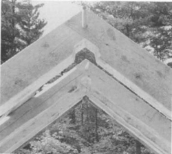
The rafters are reduced to 4½ inches where they join at the peak in an open mortise-and-tenon joint.
Most of the rafters have a 9-in-12 level cut at the foot where they are nailed to the raising plate.
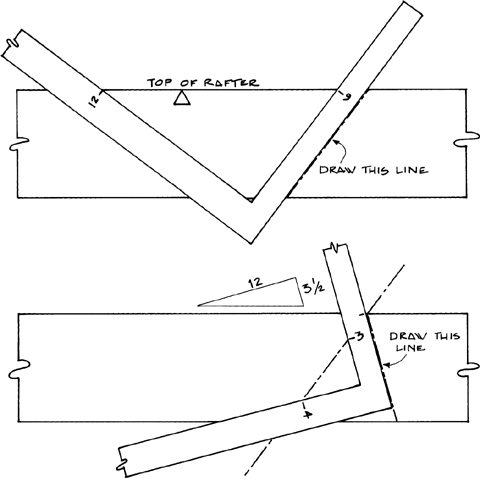
Though the rafters are tapered, the layout is straightforward as you reference from only the best face and edge. As long as the rafters are at least 4½ inches wide at the peak for the joint, the taper doesn’t matter. To lay out the peak joint, however, you need to figure the angle, which is based on the roof pitch of 9-in-12. Finding the angle that the rafter makes with its mate is a two-step process. On a wide board or piece of cardboard or plywood — possibly even your shop floor — lay out your 9-in-12 plumb line off a straightedge. This is the angle where a conventionally framed rafter would be cut to butt a ridgeboard. Lay out another 9-in-12 pitch off this line (you can use any measurement in the same ratio, such as 3-in-4, 6-in-8, 7½-in-10, and so on). This is our rafters’ angle. If you have a bevel square, set it for the angle this line makes with the straight edge. You can also use the framing square and determine what number in-12 it is, which in our 9-in-12 pitch is 3½-in-12. Use this angle for all the peaks. The lengths all have to be figured with the Pythagorean theorem (see the section on braces earlier in this chapter). Note that the tenon at the peak is ⅛ inch short to allow for shrinkage.
Sawing the long angle cut at the foot is tedious and the saw often wanders on such cuts. Touch up the cut with a plane as necessary. The tenons at the foot are cut similar to braces but have a shoulder on either side. Saw out the notch first, then lay out and cut the tenon.
Laying out the peak angle. First lay out a 9-in-12 plumb line at the peak. Then, lay out another 9-in-12 (or similarly proportioned) line off the plumb line. This second step is best done on a wide board to be accurate. Record the angle with a bevel square.
When each timber is finished, I usually take a plane to chamfer (bevel) each edge of the timber. A 1/16-inch chamfer softens any sharp, ragged edges. On waney timber, I remove the bark with a drawknife or chisel and spokeshave it smooth and uniform. If you don’t like the rough-sawn surface, you can also plane the exposed faces. To prevent tearout of grain, I use a smoothing plane with a slightly rounded iron and push the plane diagonally across the face in a slicing motion. Planing lengthwise in the direction of movement is more likely to cause tearout. You should plane reference faces that are exposed before you lay out, because otherwise you are reducing the thickness slightly and the joints may be less tight.
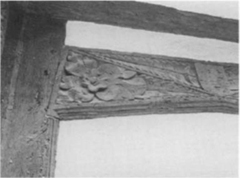
Ornate carving was fairly common in English villages.
Stop chamfers dress up a frame. This simple yet attractive stop chamfer was chosen for our project house frame.
In many early house frames, builders added decorative stop chamfers, which taper at one or both ends. These dressed up the frame and made it more user-friendly. In more expensive European frames, a lot of carving work embellished the frame. Here in America, frames were less fancy. By the time the Square Rule became popular, frames were no longer exposed on house interiors except in attics and cellars. Thus, there are very few (if any) old Square Rule frames with stop chamfers. Though it is a peculiar marriage, I sometimes use them. Mine are 1½ inches wide and the stop is 4 inches from the joint. The curved stop has ¼-inch reveal, a style that was probably the most popular as it was attractive, yet easy to cut. A line was drawn on each exposed corner that was 1 inch from the edge on either face. A saw kerf was made at each end, 4 inches from the joint, down to these lines. The wood in between the kerfs was scored with an ax, pared with a slick, and finished with a plane to the lines. The ends were cut back 2 inches in a graceful curve to leave the ¼-inch reveal. These curves are quickly cut with a chisel.
The post at the foot of the stairs, shown opposite, being a sort of turning point, was chamfered to make it octagonal, with stops that were beveled back rather than curved. This post could also be turned on a makeshift lathe to create a decorative newel post. A better solution is to select a smooth 8-inch diameter log, strip its bark carefully, and frame it as a post.
Support the timber at a 45-degree angle and lightly score it with an ax every two or three inches.
Pare to the line with a slick and smooth with a plane.
Cut the curve carefully with a chisel, bevel down. Leave a reveal of about ¼ inch.
The finished stop on a maple timber.
An octagonal stair post.
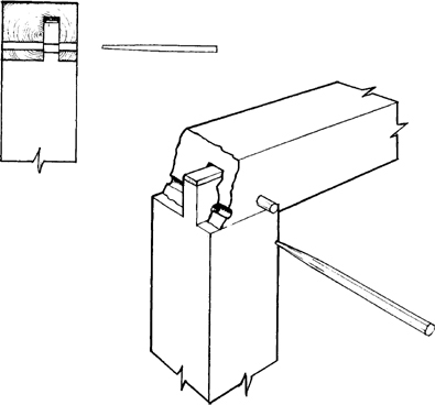
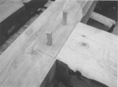
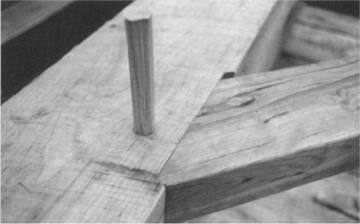
How drawboring works.
The billet is marked into four-peg squares. With a froe and heavy mallet, keep splitting the billet in half.
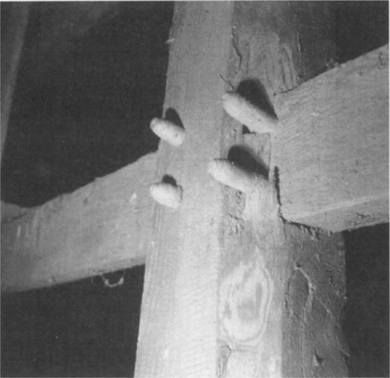
Sometimes referred to as pins, trunnels, or treenails in old writings, pegs are an important part of the system. They draw and hold joints together. In most old frames, pegs were octagonal in cross section and tapered to a blunt, square point. By driving a tapered peg through offset holes, the joint was brought tight without other mechanical aids. In fact, this drawpinning system would keep joints tight during the racking of assembly and even after shrinkage. It may seem easier to bore the peg holes after the frame is assembled and pull the joints tight with come-alongs, but it isn’t — it is a lot more work and the joints won’t stay tight! If you use the traditional drawpinning system, all peg holes are bored as the timbers are worked, you won’t be boring holes up in the frame later, and you shouldn’t need any come-alongs, either.
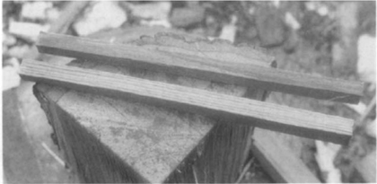
Pegs are quickly riven or split out of freshly cut billets of a straight-grained clear hardwood. Cut the billets 4 inches longer than the deepest peg holes. In this frame, most pegs should be 12 to 14 inches long, with the pegs securing the rafter peaks measuring about 8 inches long (I’ve used 13/16-inch diameter pegs, but ⅞-inch ones are all right). On the end diameter of the billet, lay out a grid of 19/16-inch squares for 13/16-inch wide pegs (or 111/16-inch squares for ⅞-inch wide pegs). Using the froe and a froe club, first split the billet into quarters, and then split each quarter into two peg-wide sections. The most important principle of riving is that the split follows the grain if there is roughly equal wood on either side. If not, the split runs toward the narrower side. Thus, when riving peg blanks, you should be continually halving the sections until you have a blank approximately 13/16 inch (⅞ inch) square that exactly follows the grain. If you encounter knots, wavy or curved grain, or sapwood, throw the piece in the firewood pile.
Keep riving down to a square, split those squares in half, and then split those in half again.
You should be left with straight, even, and square stock.
Pegs should be shaped while still green or you will work a lot harder. They can be shaped with a shaving horse and drawknife if you have them. I use a jig to hold the blanks while I use a chisel and hand plane to shape them. My jig is a board with a V-shaped slot to hold the peg with a small block under the board to keep it from sliding. First, put a 3- or 4-inch long tapered point on the end opposite the layout end. Hold the blank with one hand and pare with a chisel in the other. Then hold the point end and pare the four edges off to create an eight-sided peg. If the blank was accurately split to size, you will end up with a peg that has alternate riven and pared faces within a couple of minutes. For a straighter, more uniform peg, use a block plane instead of or after the chisel. When finished, the distance across the flats of the octagon should be slightly less (1/32 inch) than the peg hole diameter and the distance across the corners of the octagon should be slightly greater than the hole diameter. Thus, when the peg shrinks, its corners should still dig into the sides of the hole. Because each peg will be driven through offset holes, however, it is not the fit of the peg in the hole that makes the joint tight. Allow a couple of weeks of drying time before using. Green pegs mash or split easily when driven and, of course, shrink and loosen.
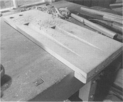
You need to make a simple board jig to shape the pegs with slots to hold the pegs and a couple of holes to check the fit of the finished pegs.
Pegs are held in one hand and shaped with a chisel or plane in the other.
In a couple of late nineteenth- and early twentieth-century frames, I have found lathe-turned pegs. Obviously, the builder had access to a woodworking shop. But turned pegs weren’t common. Today, many framers are using turned pegs. For strength and appearance, I still prefer riven, hand-shaved, octagonal pegs.
Peg holes were laid out with the framing square as a template, which is necessary for proper drawboring/drawpinning. Most peg holes are 1½ inch off the shoulder of the joint. The mortised peg hole is bored right on the mark, but the tenon peg hole is bored about ⅛ inch closer to the shoulder from the mark. This ⅛ inch is not measured, just eyeballed. If it is a little more or a little less, the amount the peg is driven can compensate. Pegs are driven until they sound right.
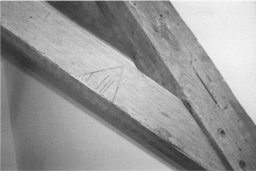
These identification marks are on a structure in New Orleans.
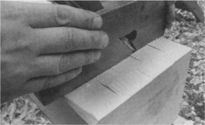
With Scribe Rule framing, you must mark all the components for reassembly; each piece has a number or mark corresponding to the adjacent timber. In Square Rule framing, though, every piece need not be marked as there are many interchangeable pieces (floor joists, braces, and rafters), and many old Square Rule frames were not marked at all. These marks can be Roman numerals cut with a chisel, a race knife (timber scribe), or ink, crayon, or pencil marks. I will describe a traditional marking system. The bents or crossframes are numbered I, II, III, and IIII starting from the west. In old frames, the Roman numeral IV was not used for four as it was too easy to confuse it with six (VI). Likewise, VIIII was used for nine instead of IX. Sometimes the nine was a V with a I inside. I mark the timbers on the north wall with a 1½-inch chisel and the timbers on the south with 2-inch chisel marks. A timber that spans from the north wall to the south wall, such as a girding beam, will have the same number at each end, but the numbers will have different sizes. Numbers are always on the primary reference face and are cut across the grain. Use two chisel cuts to create a V-shaped incised number. Thus, with only four numbers and two chisel sizes, the entire house frame can be labeled.
Lathe-turned pegs were used in this late nineteenth- or early twentieth-century barn in Windsor, Massachusetts.
This girding beam has three 1½-inch chisel marks. It is located in the third bent on the north end and its reference face is up.
When finished with a timber, stack it in an orderly pile that allows air to circulate. Stack the parts in numerical order with identification numbers facing up. If like members are all stacked side by side and the ends lined up, mistakes in length are easily spotted. Check off timbers on the drawings as they are finished.