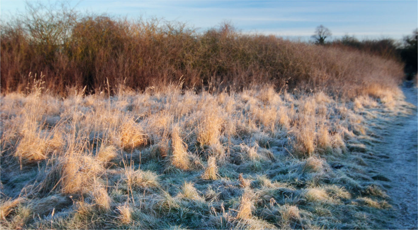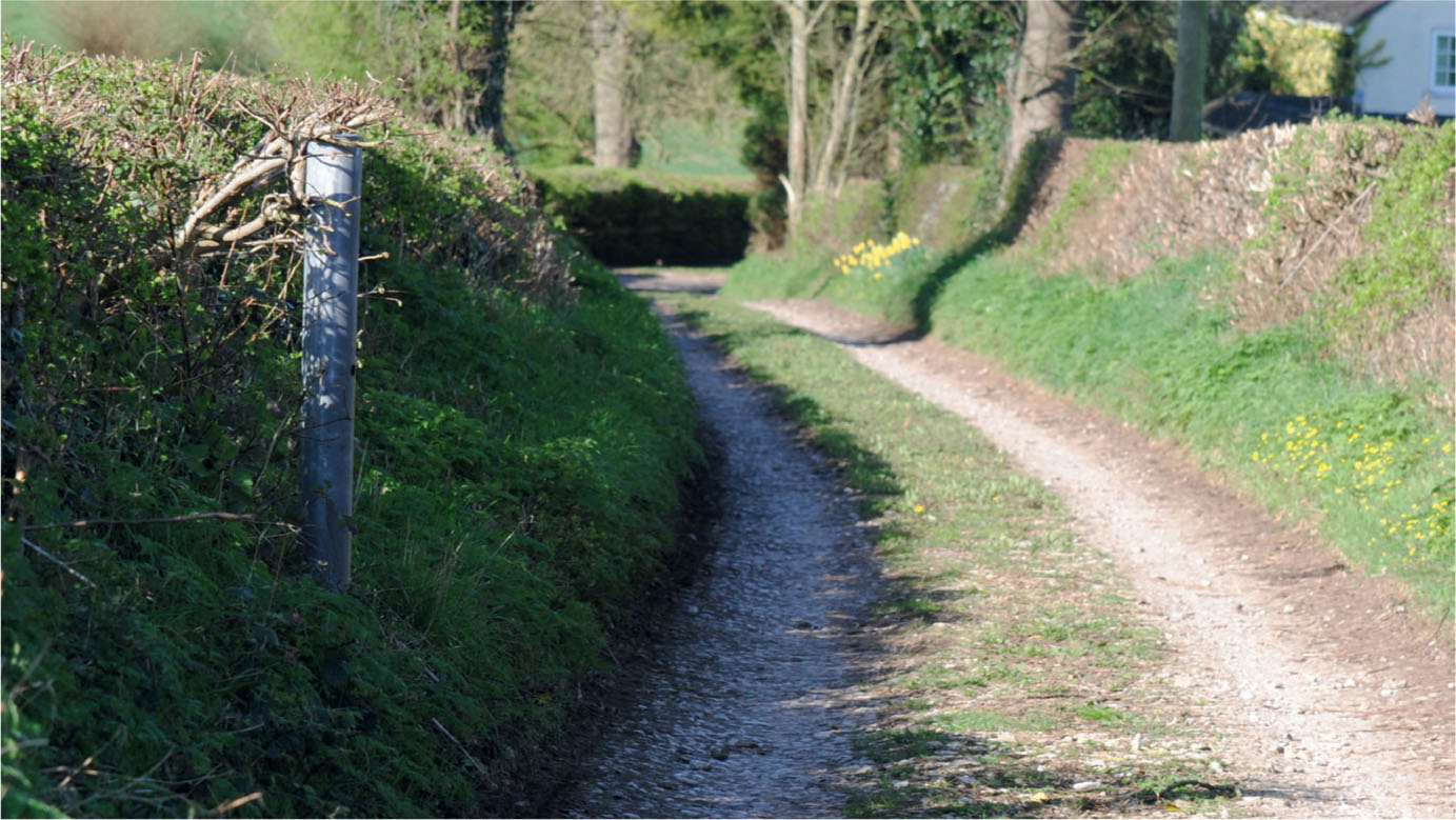
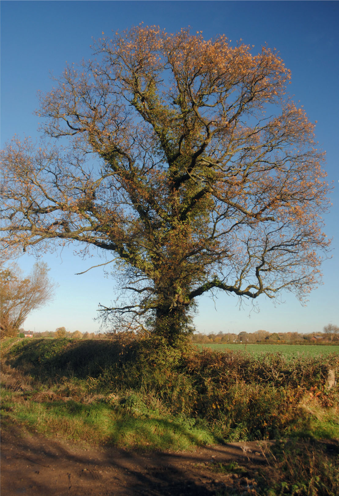
A typical rural country lane.
ALONG THE COUNTRY LANES
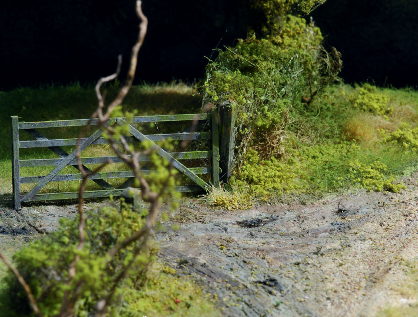
Leaving the village, we will take a stroll along a lane as it winds through the rural countryside. The lane is flanked immediately on either side by hedges. Further down the lane on both sides there may be storm ditches, which are intended to take excess surface water from the lane as well as drainage from the fields, thus reducing the risk of flooding. Later on gaps appear in the hedgerows where a five-bar gate blocks the entrances to a field. The lane may also be lined with trees, with some growing along the line of the hedgerow. Species now seen include oak, ash and sycamore, though the mighty elms of the past have largely disappeared.
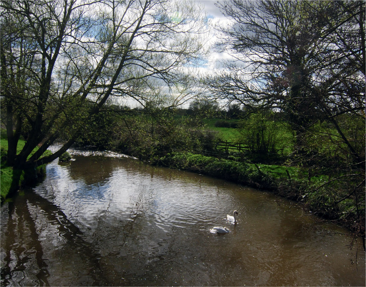
Running water can be heard as we turn a corner and drop down a slight slope towards a stone bridge crossing the river. A ford runs alongside the bridge and downstream can be the heard the sound of water tumbling over a weir. We pause for a while and watch a pair of swans bobbing in the waves formed where the tail race of the mill enters the main course of the river.
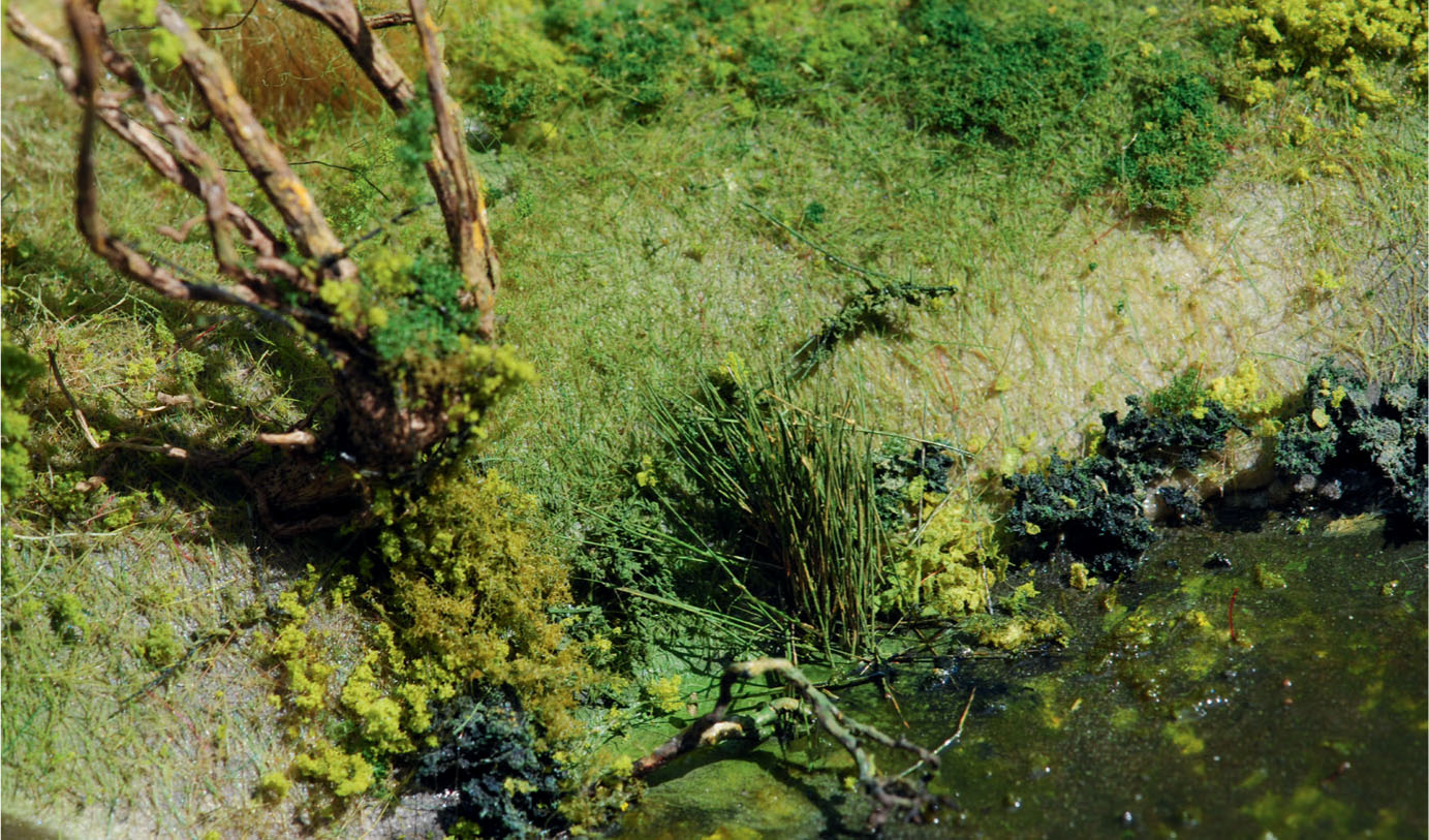
Further downstream the valley floor passes the entrance to a farm. Before long the lane splits to form a small green area with a pond alongside. The still waters are lined with bulrushes and other marginal plants; a branch from a dead tree has fallen into the water. Some of the ducks are resting by the edge, while others swim and bob under the surface looking for food (country ponds are the perfect habitat for small fish, crustaceans, freshwater snails and amphibians).
Beyond the pond the verge to the lane is just wide enough for a family of travelling gypsies to set up an encampment. A dog starts to bark as we approach the solitary caravan, decorated in traditional style, squeezed onto the strip of land. A woman stands in the doorway, beckoning to tell your fortune or sell some lucky heather. The remnants of the camp fire are seen close by, along with the horse tethered to a sturdy post.
Further down the lane a thicket of trees brings a patch of dappled shade. Around the next corner, where stands a small timber-clad and thatched hay barn in need of attention, a narrow lane joins from the side. Here we will pause for a while to consider how some of the rural features we have seen along the journey might be modelled in miniature. This will lead to a series of projects designed to offer inspiration and practical advice on the materials and techniques used, as well as all the painting and finishing stages that will help create a realistic model.
A typical rural country lane.
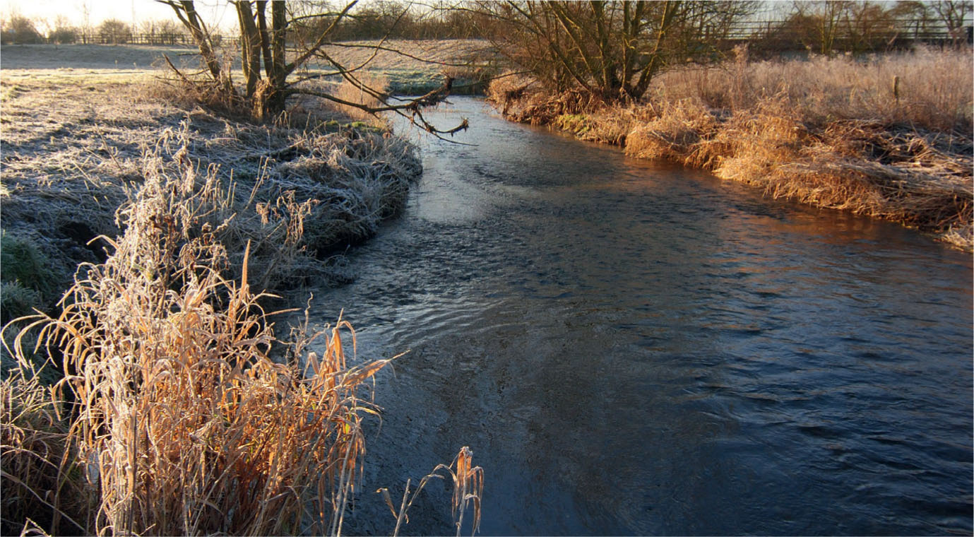
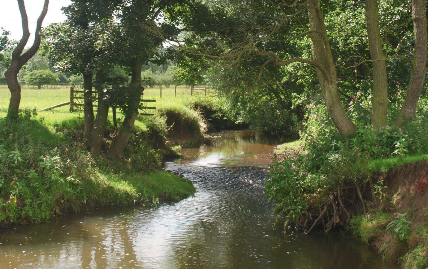
A typical rural freshwater stream.
TREES IN THE RURAL LANDSCAPE
It is impossible to compile a book about depicting the rural scene without mentioning trees. Most rural landscapes will feature trees of some kind, either grouped together to form woodland and forest, or individual trees scattered along the borders of fields and country lanes. Trees have come to symbolize our green and pleasant land, so at some time every modeller will be confronted with the challenge of how to create them successfully.
Before tackling this, however, we must first observe the prototype and record what we see and not what we think we see. From childhood we tend to perceive a tree as having a brown trunk and branches with bright, vivid green leaves, but this is far from the reality of most native species. Nearly all the broadleaf species of British trees, for example, have bark that tends to be different shades of grey. This is often tinged with green, especially on one side of the trunk and branches, while some trees can appear green all over due to algae growth on the bark.
One very common species, the silver birch, sports a papery white bark with dappled areas of dark brownish grey, which are more prominent on older mature trees. Sometimes shades of reddish brown or pale ochre are visible within the markings of the bark.
The foliage can vary immensely from very broad leaves to small roundish leaves, or to large fan-shaped leaves. Some species, such as willows, have long narrow leaves, while others, including the ash, have small roundish or narrow leaves joined to a stem.
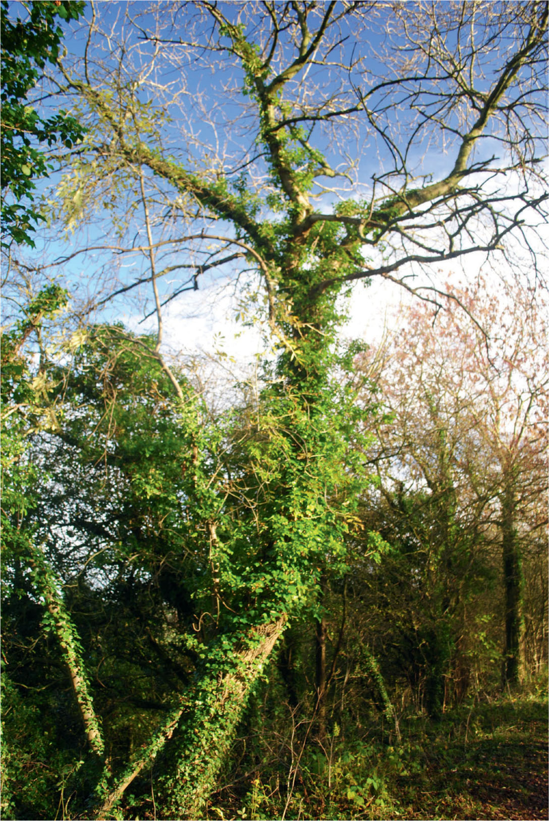
The bark on the trunk and lower branches can also carry various parasitic growths. Ivy is possibly the most common, with its rampant evergreen growth sometimes completely engulfing the whole tree until it eventually kills its host. Ivy can vary in colour from very dark to much lighter shades of green. Other common growths seen on trunks and branches are the vast variety of lichens, which may range from bright orange and ochre to pale greens and pale greys. Dead ivy can remain clinging to the tree, creating a spooky appearance that resembles varicose veins.
Trees, of course, are often kept in check or used as a commercial crop. One common form of control is pollarding, where the upper branches are cut back to create a knuckle from which new branches will grow. Cutting trees right back to ground level is known as coppicing. This contains the new growth and creates straight branches that can then be used for building materials or rural crafts.
In addition to the native broadleaved or deciduous trees, there are numerous species of coniferous trees ranging in size and spread, including pines, firs, spruce and yew trees. Many of the coniferous species growing in the British Isles, however, are not native but have been introduced to supply the demand for timber or for paper production. Among these species are a few that do feature brown bark, although it may be more accurate to describe them as a reddish-brown shade. Others follow the broadleaved species in having trunks that are mainly green or a shade of grey.
MODELLING TREES
We must now consider how to recreate trees for inclusion on rural layouts and dioramas. It is always worth taking the time to model trees, but achieving ones that are realistic is not easy. Before attempting any modelling, research in the form of observation and recording is always recommended. Observation will always be the modeller’s greatest resource, and it has never been easier, now that there are so many ways to make an instant photographic record, to retain what you have seen for future reference.
Instead of going into modelling trees in greater detail, I would advise any modeller looking for a detailed guide on the subject to seriously consider acquiring the impressive books by Gordon Gravett listed in Further Reading.
I will, however, give comprehensive descriptions for those required for the model diorama projects presented in this book and explain how prototype photographs can help our approach to modelling them. This will be taken a stage further by suggesting alternative methods of applying colour to those described by Gordon Gravett.
The painting and finishing of any model is always going to be an important factor in determining how accurate models appear. When modelling trees, however, no precise dimensions need to be followed when it comes to working to scale. It is more a case of whether the trees look right in scale to their surroundings. On this subject, don’t forget that perspective dictates that any trees included towards the back of the layout or diorama should be smaller in order to appear visually correct. The colour will also become less intense with perspective, so again be subtle when applying colour to the trees in the distant areas. For this reason I have included a painting and colour mixing guide to help modellers achieve realistic results when creating a miniature version of a rural scene. This is similar to one I included in an earlier book, Making Rural Buildings for Model Railways (Crowood Press), to give the modeller a point of reference to refer to at the painting stage for realistic results.
HEDGEROWS AND DITCHES
Probably the most common type of boundary used in the UK for marking the sides of lanes or the fields themselves is the hedge, basically a man-made boundary intended to keep livestock in and undesirables out. Each hedge may comprise a number of different species, some selected and planted, and others self-seeded.
As with trees, from time to time hedges will need to be kept in check, which is where the country craft of hedge laying comes into practice. The process involves cutting about halfway through all the tall growth, about one foot above the ground, and then bending it over in one direction and staking it down. New growth is encouraged to grow vertically from the laid wood, creating a natural barrier. When this has grown too tall again, the whole process will be repeated.
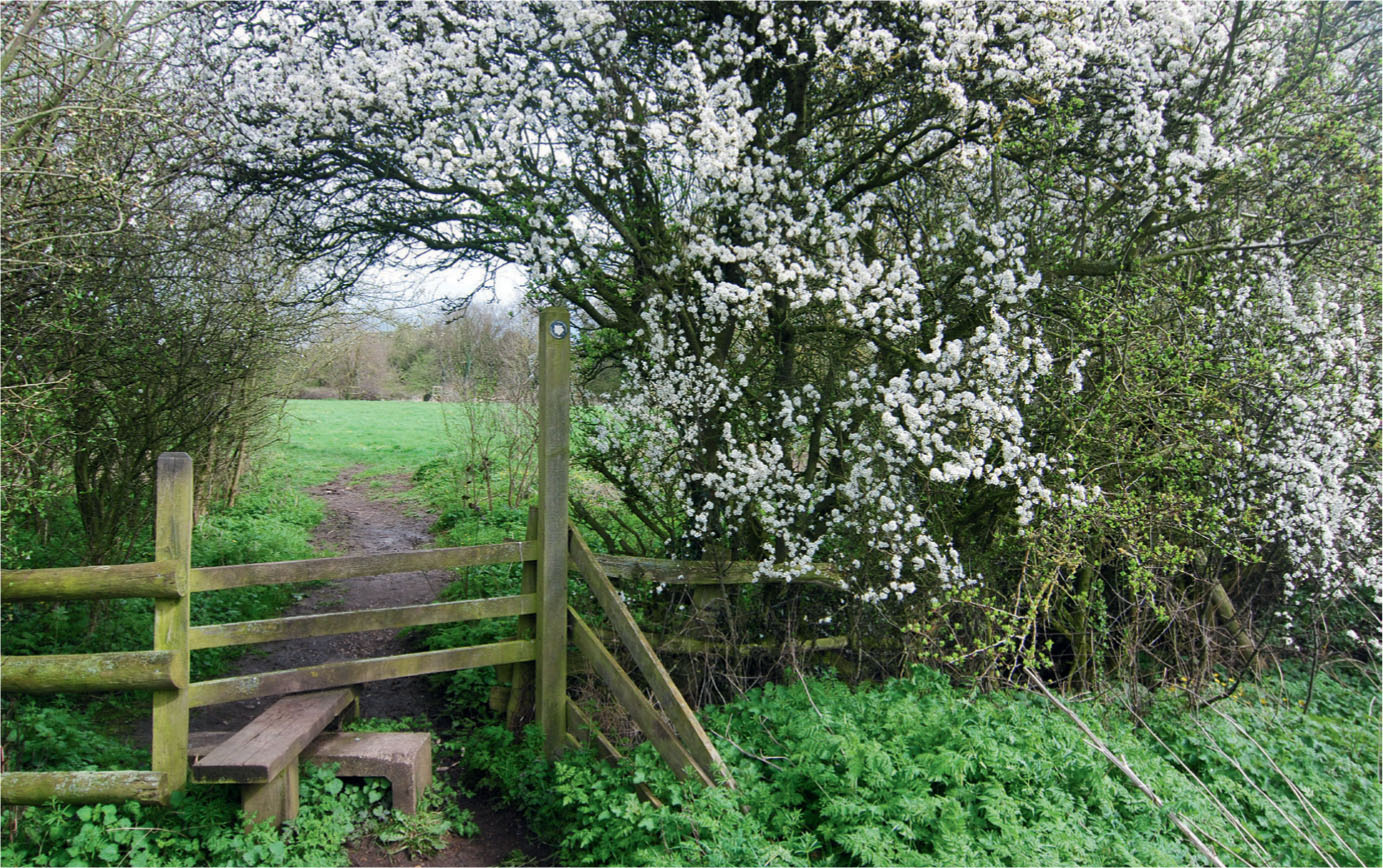
In early spring the hedgerow explodes with blossom.
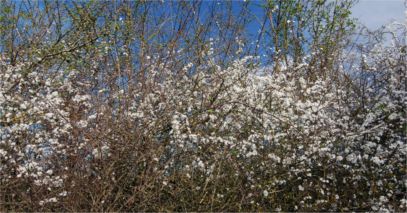
A close-up of the hedge in early spring.
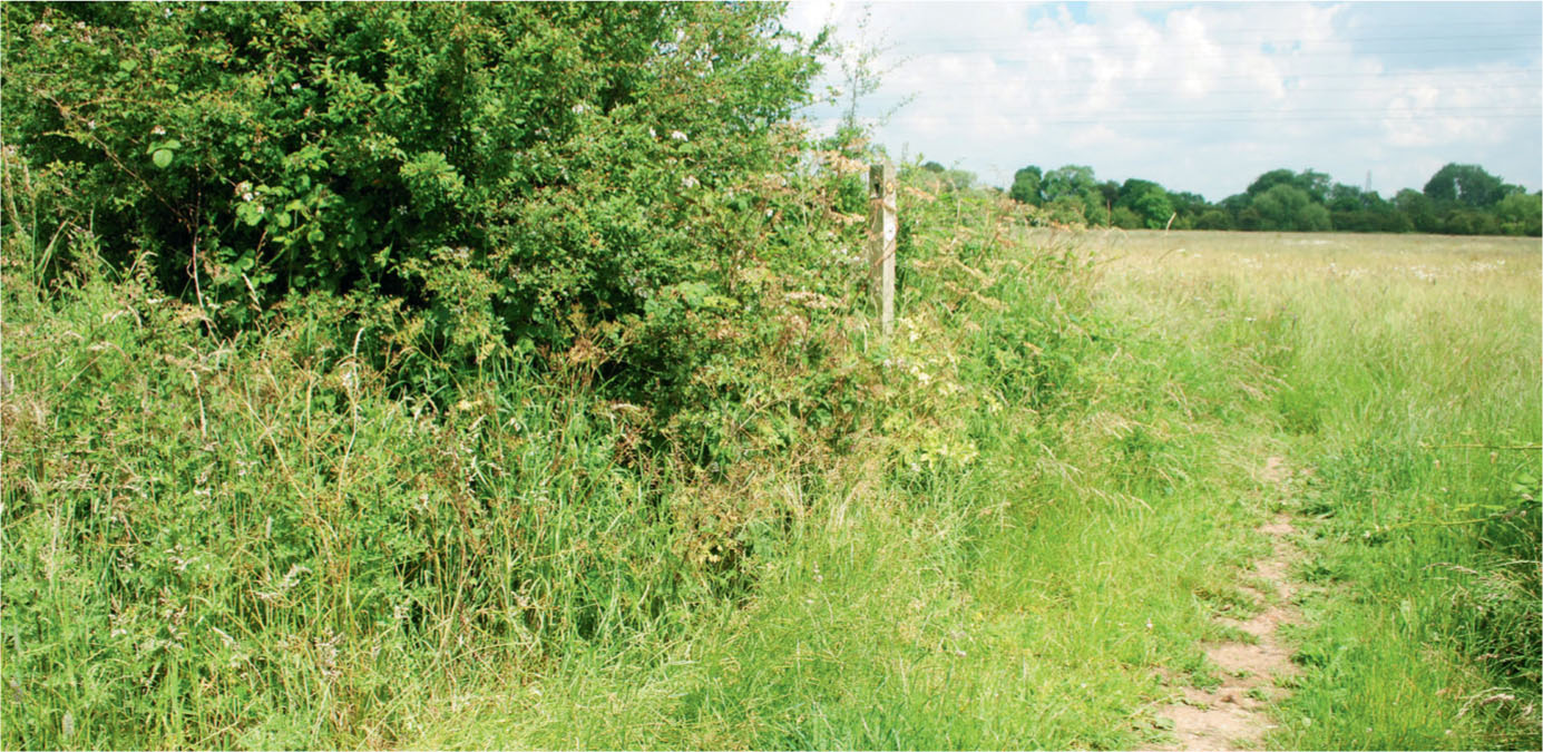
The hedgerow and verge in the middle of summer.
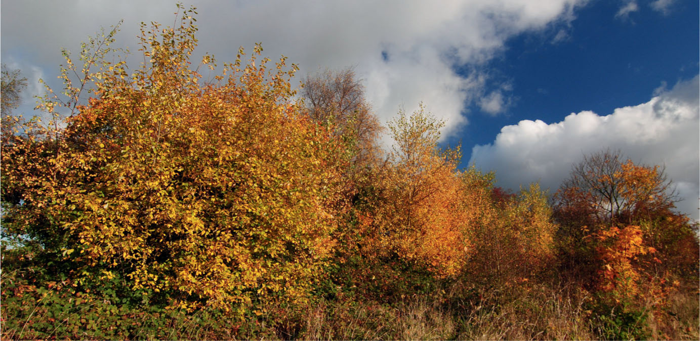
The colours of autumn taking over in the hedgerow.
Although species such as blackthorn may be used for this type of hedge, the favourite is hawthorn, which is perfect for the job, being very hardy and tough, while its thorns are a natural deterrent for animals trying to get through or over the barrier.
Both the hawthorn and blackthorn hedges take on various guises depending on the season of the year. A hawthorn hedge, for example, may have a drab appearance throughout the winter, but will suddenly explode into colour in late March and early April as its blossom creates a spectacular display along the field boundaries and beside the roads.
Once the blossom has gone, however, the hedgerow will turn green as the leaves take over to form a dense gown of foliage that will last right through the summer months. From late September the green will turn towards russet brown as the hedgerow takes on the colours of autumn. In time the leaves will fall, leaving the branches bare once more, and the cycle will start all over again.
Hedges may also include a few species that don’t lose their leaves. Holly, for instance, can commonly be found growing along hedgerows, perhaps deliberately planted as another prickly form of deterrence to keep animals from escaping.
Just as with trees, observation is the key to recreating a realistic-looking hedge. It is worth taking country walks at different times of the year to observe how the hedge changes over the seasons. Recording this photographically will establish a base of reference for when it comes to creating a model and help you decide the season of the year in which you wish to set your model.
The best material available as a starting point for modelling a countryside hedge in any season of the year is rubberized horsehair, which is readily available from most scenic suppliers and can be very effective. The material was used for upholstering furniture before foam rubber became common. Similar materials are available from various scenic suppliers. If you require a well-maintained and clipped hedge, for example, try using cooker hood filter pads.
All the materials will need to be cut, while the horsehair should be teased out and roughly trimmed to size and shape. This will be more apparent on a winter hedge, which will have little or no foliage added to it. Once the sections of horsehair have been cut to a rough shape they will need to be painted. I normally use matt grey and green spray paints from the Humbrol military range. If you have an airbrush you could also mix the colours and apply them that way. Always refer to your photographic reference or study the real hedge before painting. Once the material has dried it can then be positioned and glued down. Even when making a winter hedge it is always worth adding flock at the base, where weed growth and dead leaves always congregate. Adding this extra material will also help bed the hedge into its final position on the model. You should always select the finest flock produced for whatever range you choose; the flock used here comes from the Woodland Scenics range.
When making a winter hedge, don’t forget to look into including some evergreen species of growth within the hedgerow. The most commonly found are ivy and holly, but others such as yew may often appear. Adding a few of these will bring a little more interest to a winter hedgerow. I find the scenic materials from the Mininatur range by Silhouette Modellbau can give convincing results. These can be teased out on the fibre backing and spray glued to the fibres of the horsehair. Always follow the photographic reference in placing the evergreen growth so that it looks correct.
Hedges in early spring will have little foliage, although as new growth it will be a brighter green than later in the year. Select a green flock from the scenic ranges to match the greens seen in photographs taken at this time of year. Remember to select the finest flock available and be sparing when applying it to the horsehair fibres. It is also worth taking into consideration the scale at which we are working: don’t be tempted to select the brightest green in the range, choose a more subtle shade as this should look correct at the reduced scale.
If you are modelling a hawthorn hedge in early spring, don’t forget to add the blossom that explodes with tiny white flowers almost covering the whole hedge. Other species of thorn also feature white or light pink blossom at this time of year. To add this to the model hedge I would suggest a light dusting with very fine white scatter. Green Scene supply a fine pre-coloured flock: choose either white or light pink for the hawthorn.
In later spring the blossom will fade, leaving only a mass of green foliage covering the hedge. The colour will become less intense as the growth of the hedge moves from spring into the summer months. This will need to be addressed, if you choose to set your model at this time of year, by adding more flock to replicate the foliage in full growth.
Autumn can be the most impressive season visually, although modelling a hedge at this time of year can be challenging. The results, however, will be colourful and rewarding. Many flocks and scatter materials are available to replicate the russet colours that overwhelm the foliage during the autumn months. There is nothing better than a walk in the countryside on a clear sunny day to experience the colours first hand, but don’t forget to take your camera to record what you see.
DITCHES
Alongside the hedgerow bordering a lane, or running along the field boundaries, you will probably find a ditch. This provides the drainage required to take excess water from the surface of the lane or the fields to a stream, river or pond.
In East Anglia and on the Somerset Levels these ditches actually form the field and road boundaries. They may also be much wider in these parts of the country, where they are known locally as drains, feeding even larger waterways and rivers that have been straightened to cope with draining excess water across the flat landscape.
The country stream in midsummer.
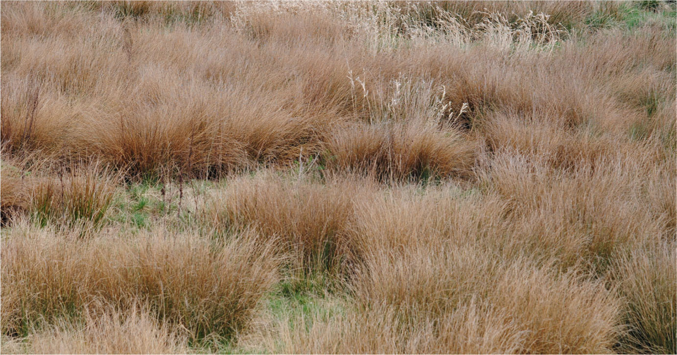
Dead grassland turns the colour of straw in the winter. The natural colour of teddy bear fur replicates this very well.
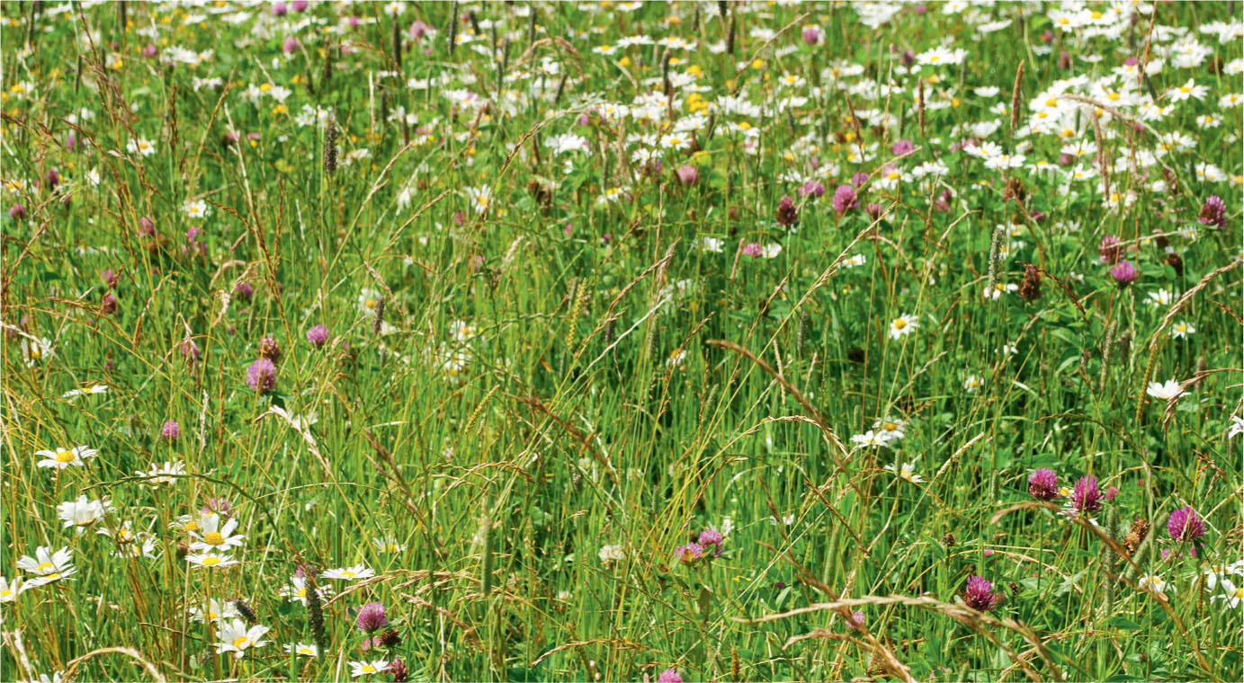
In spring the meadow grassland is a riot of colour as different wild flowers push through the emerald green grasses.
CROSSING WATER
In the past most rivers and streams, meandering across flood plains, were wider and shallower than today. This made it more practical to ford shallow stretches of river at places where the geology and depth of water permitted. Fords were commonly maintained alongside a bridge, giving an alternative if the water level was low enough. This enabled wagons and carts to pause a while, allowing the horses to drink and the wooden wheels to swell in the water, thus tightening the metal tyre to the rim. (If wagons and carts had been on the road for a while, it was not uncommon for the tyre to come loose.) A scene such as this will feature in Chapter 7, where it is an important feature in an ambitious re-creation of a famous painting.
FERRIES
The use of a ford would have been impossible on the larger and deeper rivers. One solution here was to provide a ferry, which could be one man in a rowing boat or a special flat-bottomed vessel pulled across from one bank to the other by means of ropes or chains. This type of ferry would be large enough to carry at least one wagon or cart, or later a motor vehicle, across the river. Crossings like this would be subject to a payment to the ferryman. A few ferries still survive, but bridges have replaced most of the larger river and estuary crossings.
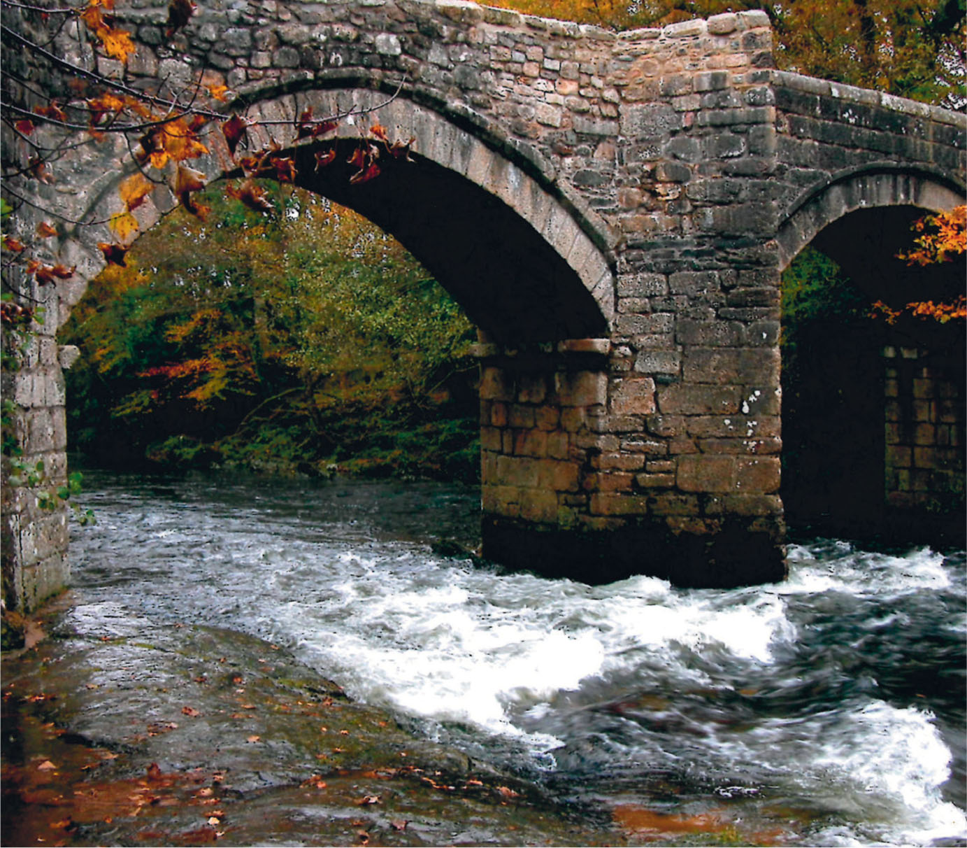
EARLY BRIDGES
The earliest bridges comprised either large timbers or stone slabs supported on substantial blocks of stone, forming what is known as a clapper bridge. A few, such as the Tarr Steps across the River Barle on Exmoor, have been standing since ancient times, but most may have been rebuilt a number of times over the centuries. The stone slabs of the clapper bridge at Postbridge on Dartmoor are wide enough to allow a small cart over the river, making it possible to transport Dartmoor tin by pack horse to the stannary town of Tavistock.
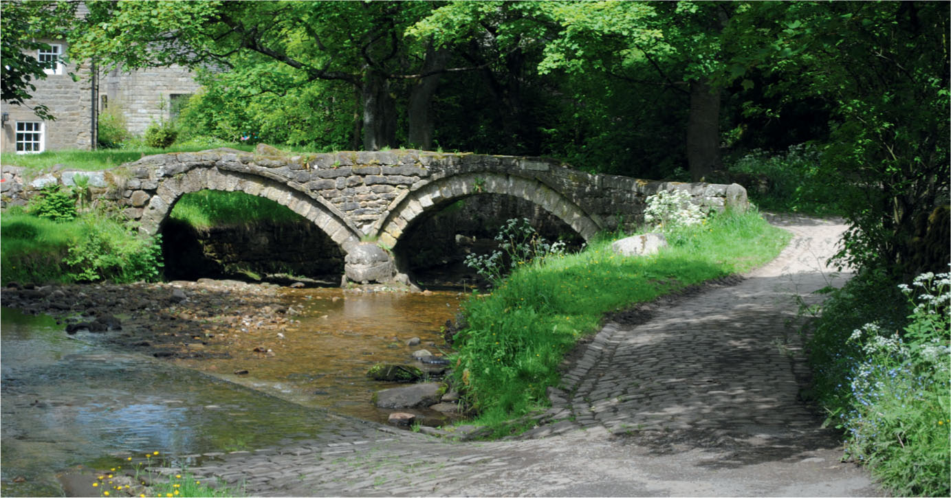
Clapper bridges were followed by more substantial constructions known as packhorse bridges, which were built on the main drovers’ roads to allow teams of packhorses to cross the river or stream. The bridges date from the early to late medieval period. While some may have had no more than three arches, Essex Bridge over the River Trent near Great Haywood, Staffordshire, has fourteen. These bridges were also built with low parapet walls so that wide loads could cross the bridge; despite its length, Essex Bridge is only four feet wide. About 190 bridges on packhorse routes in England have been suggested as falling into this category, together with a further dozen in Scotland and Wales.
Washgate Bridge, which crosses the upper reaches of the River Dove near Hollinsclough, was one of the early packhorse bridges on an old drovers’ way.
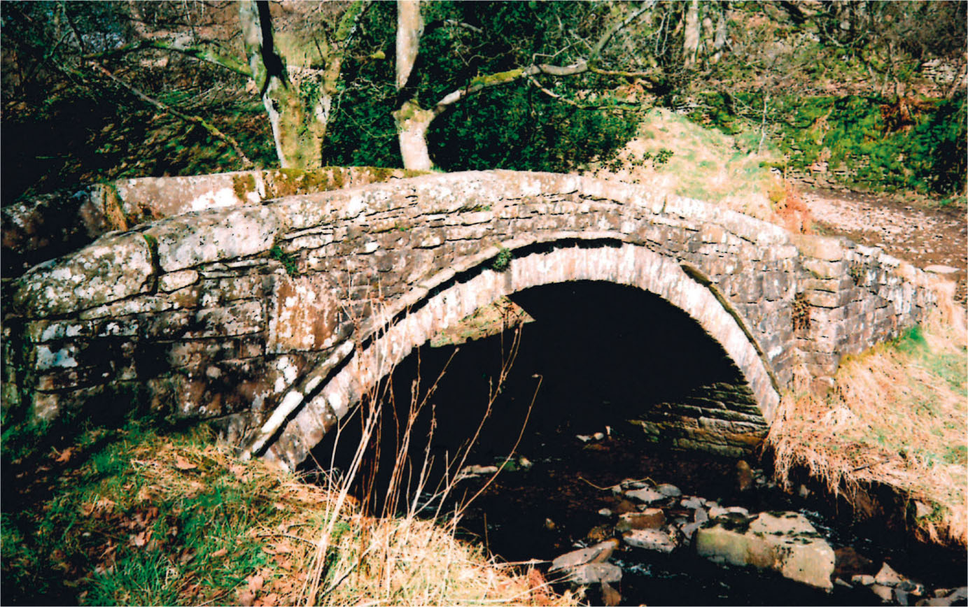
Another early packhorse bridge at Wycoller, Lancashire. Note the cobbled surface of the ford crossing the river in the foreground.
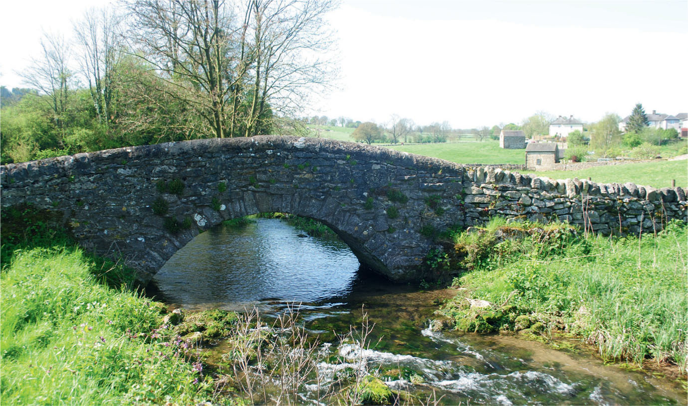
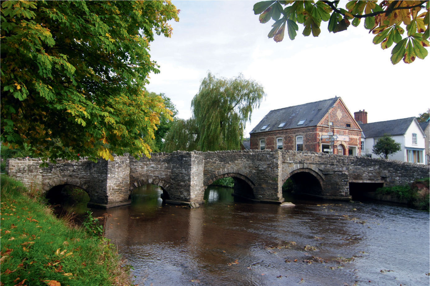
A small limestone bridge crossing the River Bradford in Derbyshire.
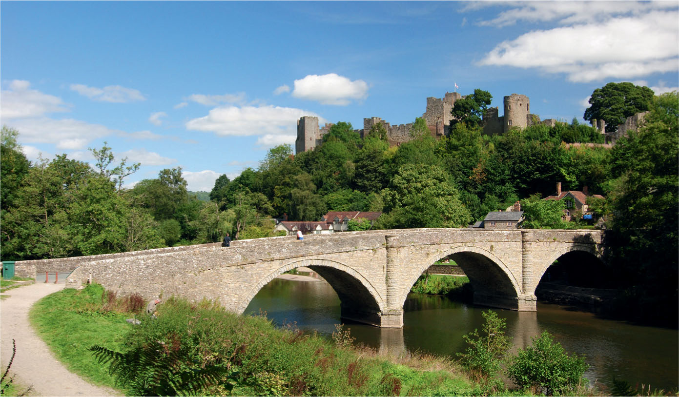
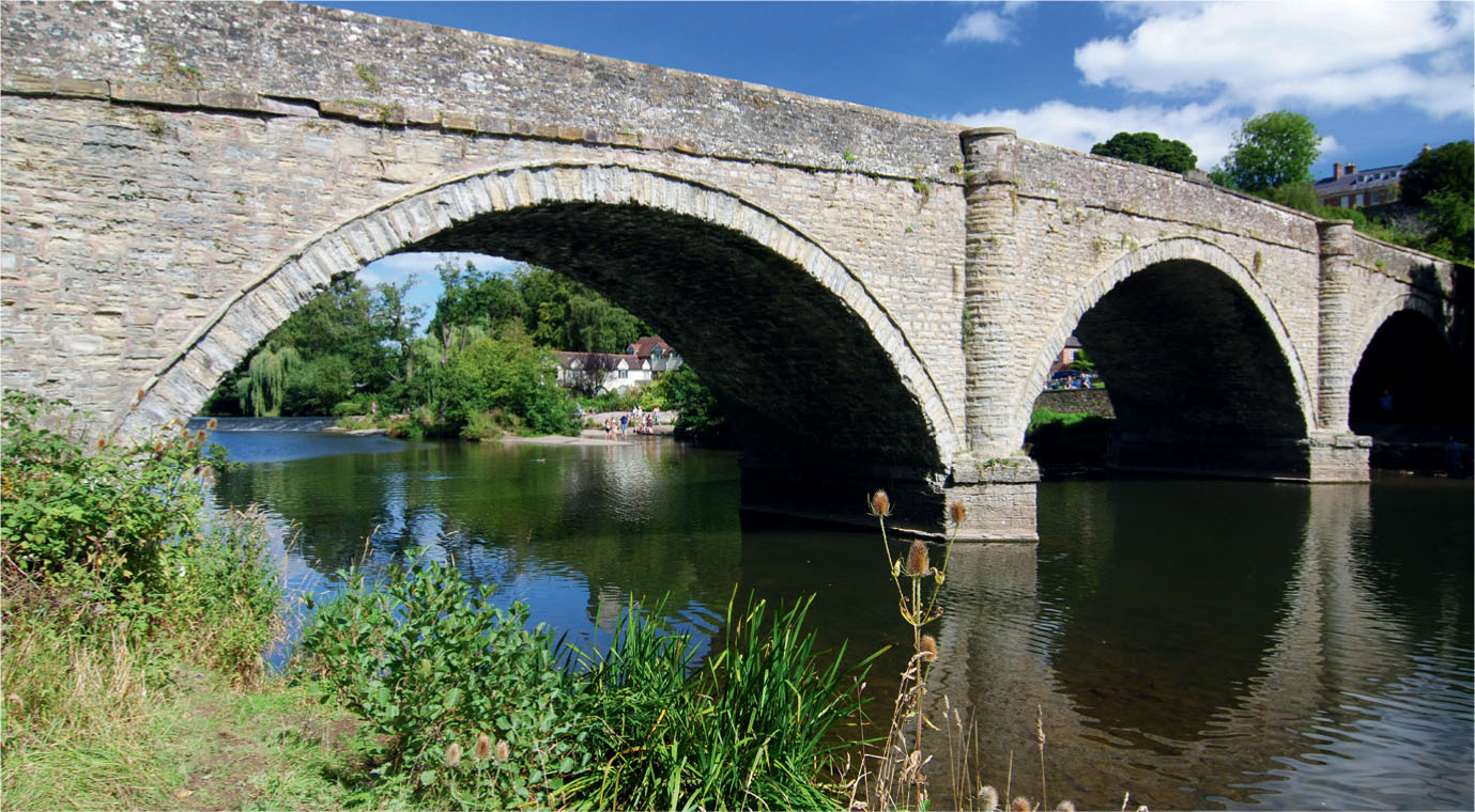
The medieval threearched stone bridge at Ludlow, with the castle in the background.
This period also saw majestic stone structures towering high above the river, many with sweeping arches springing from piers constructed from the riverbed. The construction of the pier was angled to create a point known as the cutwater, which would allow the water to flow freely around it and through the adjoining arches. This type of bridge became very common from the thirteenth century. Most featured round-topped arches, although pointed arches were also found. Many of these bridges are still standing, but their narrow width is not suited for modern transport, so a replacement has usually been built alongside.
Many new bridges, usually much wider than their predecessors, were built in the eighteenth century alongside the rebuilding of the road system by the turnpike trusts. At the larger crossings a toll was sometimes paid to redeem the money spent on building the bridge. These later bridges differed little from their medieval counterparts. Pointed arches were still popular, though more as architectural decoration than for their structural importance, especially for bridges erected in the parks of stately homes.
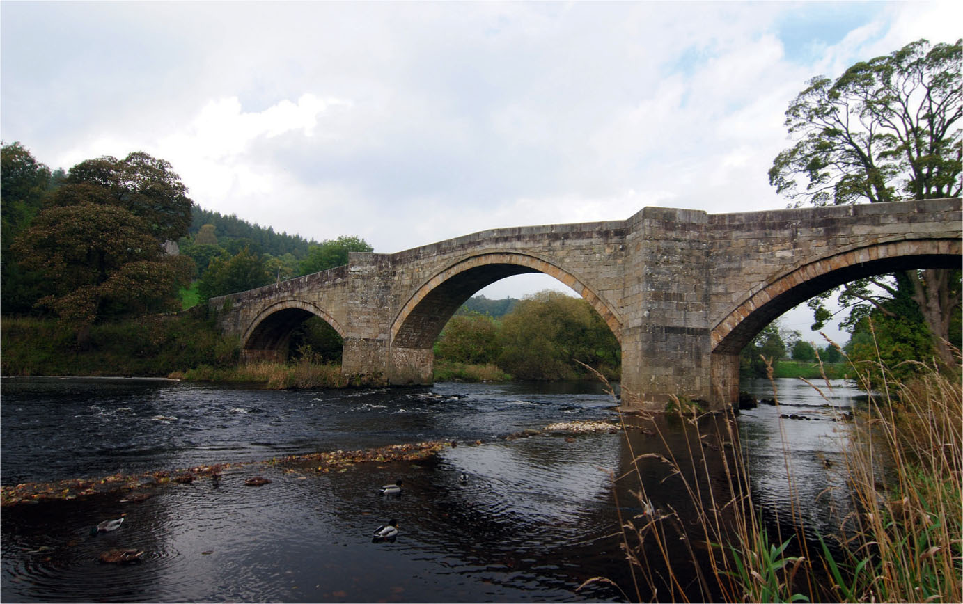
A typical medieval arched bridge crossing the River Wharfe at Barden in the Yorkshire Dales.
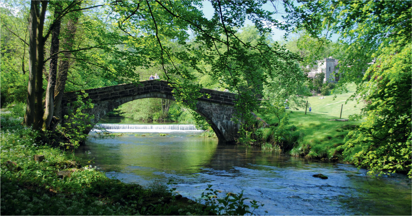
A large single-span packhorse bridge spanning the River Manifold at Ilam, Staffordshire.
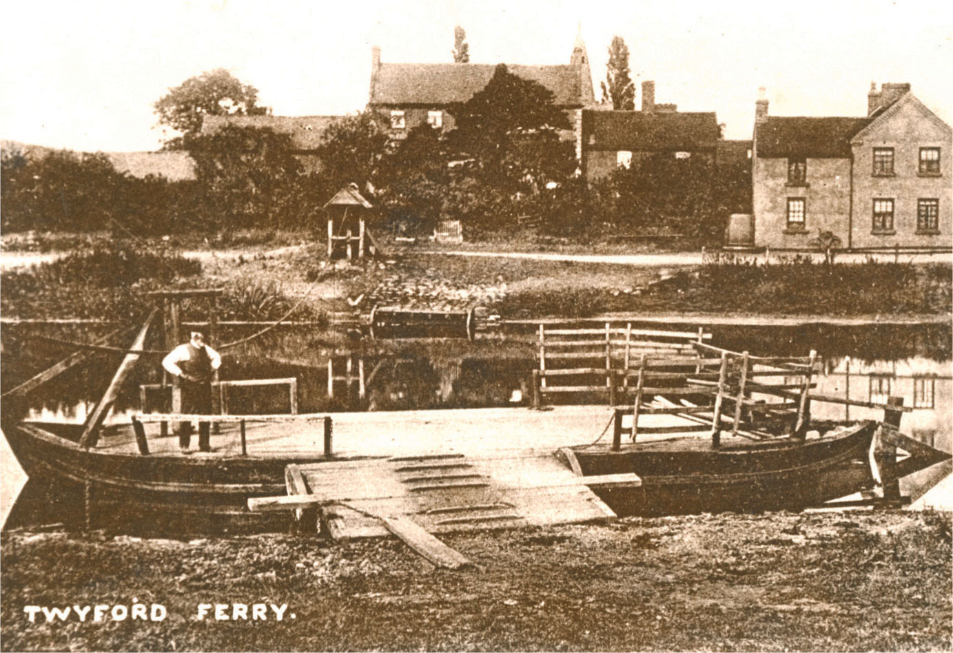
The chain ferry across the River Trent at Twyford, Derbyshire, was finally washed away by floods in 1963.
From the late eighteenth century new materials became available for bridge building. The first cast iron arched bridge was forged in sections and erected across the River Severn at what became known as Ironbridge in 1779. These bridges were cheaper and lighter than the stone types and soon became popular. Moving into the twentieth century, steel and concrete dominated the civil construction industry. The post-war expansion of the road network and the building of the motorway system also required many new bridges.
A small arched stone bridge is featured in the third of the scenic projects that follow in this chapter. The materials chosen and the constructional techniques described can be used to model many types of larger bridges.
PROJECT 1: MODELLING COUNTRY LANES
The first project here involves creating a stretch of country lane that could be almost anywhere in the country. The simple diorama features how to model the lane’s surface as well as the verges leading to a ditch and the perimeter hedgerows. The model also includes a couple of trees and a gateway into a field. This diorama has been set in the late spring and shows the natural vegetation found at this time of the year.
Every scenic model has to start with a foundation. In this case a piece of rigid card was selected, although plywood or thin MDF would also be acceptable. The panel when cut down measured roughly 12 x 9in (300 x 230mm). This would give ample room for a 1:43 scale model that includes all the features mentioned.
The next stage was to create the landform, giving the lane a slight gradient that would also allow for the depth of a storm ditch in the left-hand corner. Styrofoam wall insulation board was chosen as this would be both light and easy to shape. This board usually comes with foil bonded to the face. This was first removed and then the foam panel could be cut roughly to shape using a panel saw, allowing for a slight gradient to run from front to back. The roughly cut-out foam was then glued securely to the base using a strong PVA and left to dry.
Once dry the base was turned over and any overhanging foam was sawn off neatly to the edge of the base.
The next stage was to plot the line of the lane together with the entrance to the field and the ditch. With this completed the foam was carved and shaped to the contours of the land. The ditch required the steepest slopes to be carved, cutting right down to the baseboard underneath. Next the foam has to be sized to seal the whole surface, otherwise the material will be too soft. The best and easiest way to do this is to brush the whole surface with a liberal coating of PVA glue, making sure that it soaks well into the material. This should then be left to dry before giving the foam another coat. Two coats of PVA should be enough to seal the foam, before moving on to the next stage.
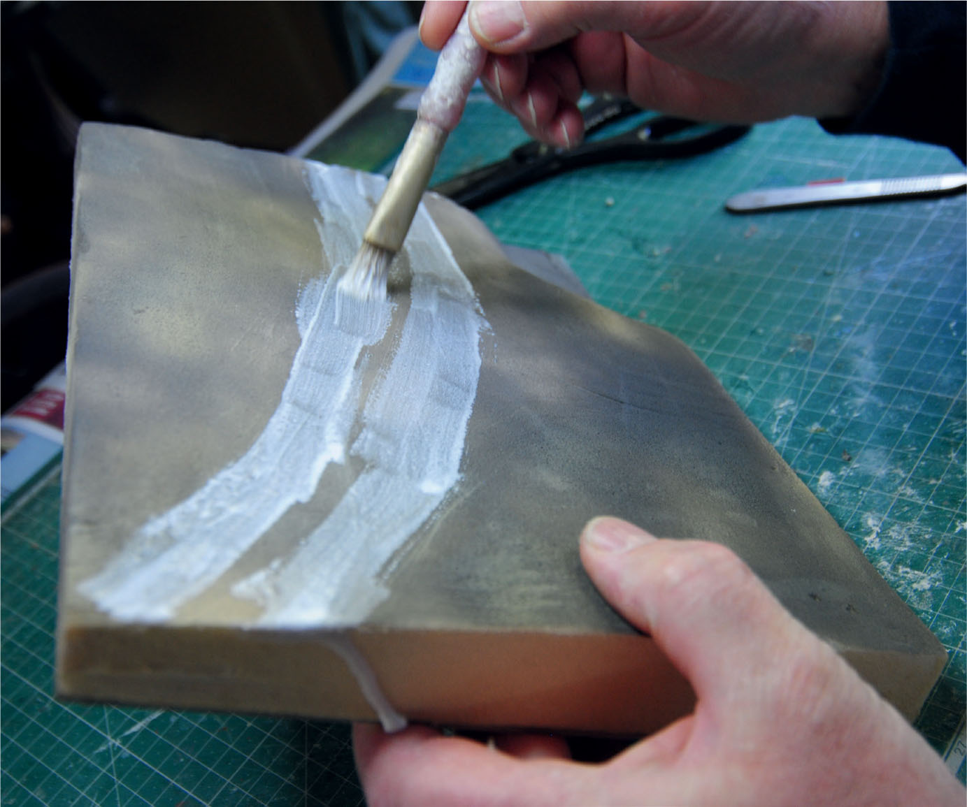
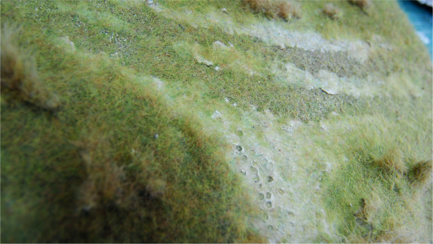
Painting on PVA is the first stage in surface texturing the lane.
Fine grit and sand is added. Das modelling clay is here applied to the side of the lane and to the gateway to the field.
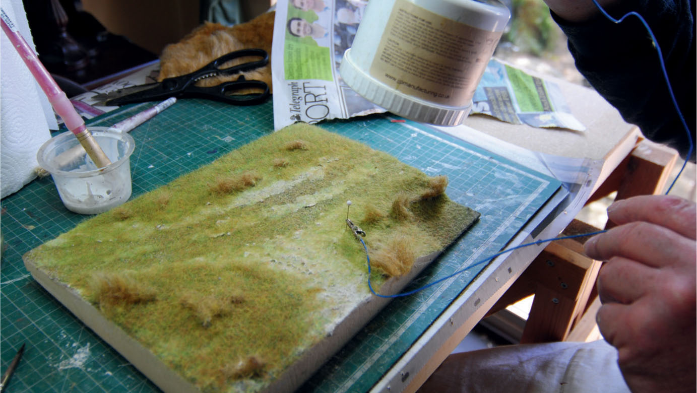
Adding static grass to the diorama using the static grass applicator.
Static grass has been added where required and the cattle’s hoofprints carved into the gateway.
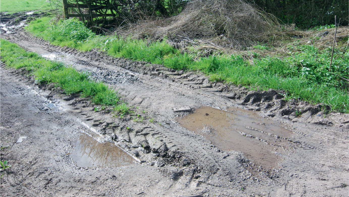
Prototype inspiration is demonstrated in the lane’s muddy verge, in which puddles have formed, and vehicle tracks through the mud into the field.
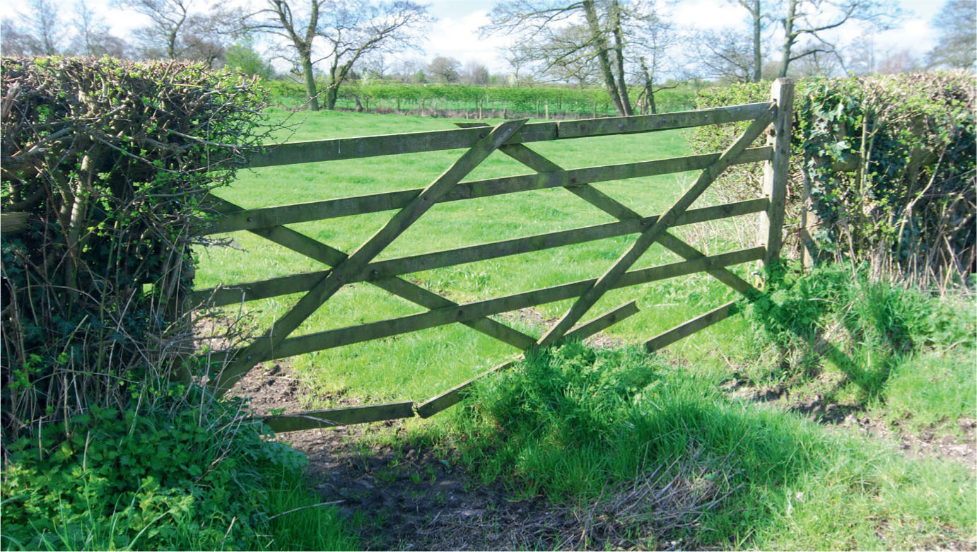
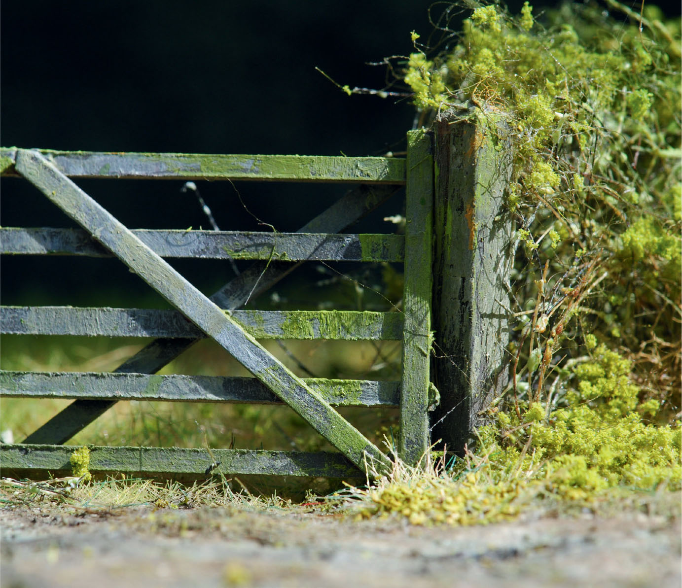
Photographic reference of a five-bar gate to use on the model lane diorama.
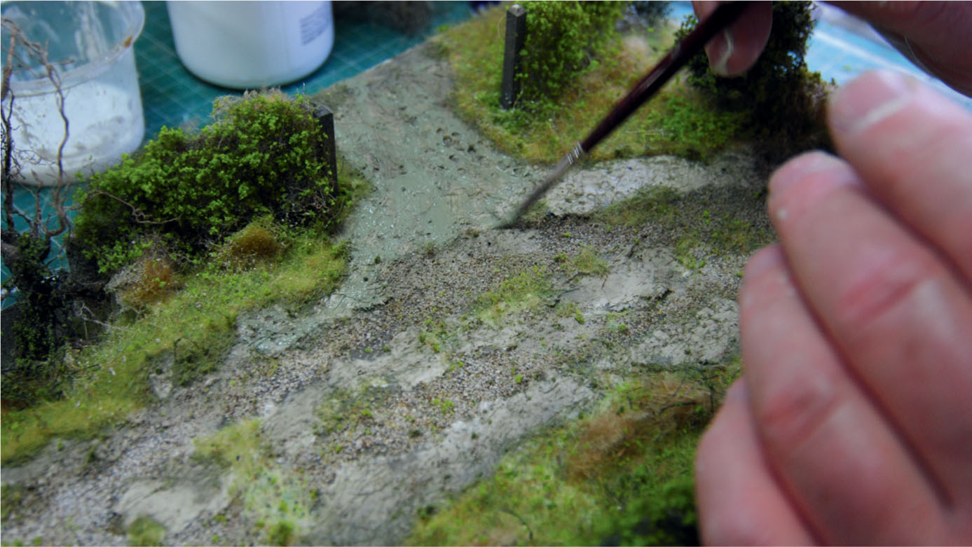
Once the second coat had dried, some Das modelling clay was spread into more PVA to create the surface of the lane surface. The clay was applied thinly by wetting the finger before pushing it into the glue on the surface. The clay was also taken into the gateway where it was applied more thickly. While still wet a stiff brush was used to gouge into the clay and churn it up. Tracks were added to replicate where vehicles had entered the field, again churning up the surface in the immediate area.
To add to this effect, depressions and ruts were gouged out that would eventually create puddles. Before this, however, the lane would require a gritty surface provided where the wheels of traffic would normally pass along. To replicate this, fine sand was scattered into more PVA that had been brushed on in two lines to follow the tracks. Once the glue had secured the sand, the whole thing was turned upside down to allow any excess sand to fall away. This created a gritty surface for just the two tracks, with a gap left for a grass strip in the centre of the lane.
MAKING A FIVE-BAR FARM GATE
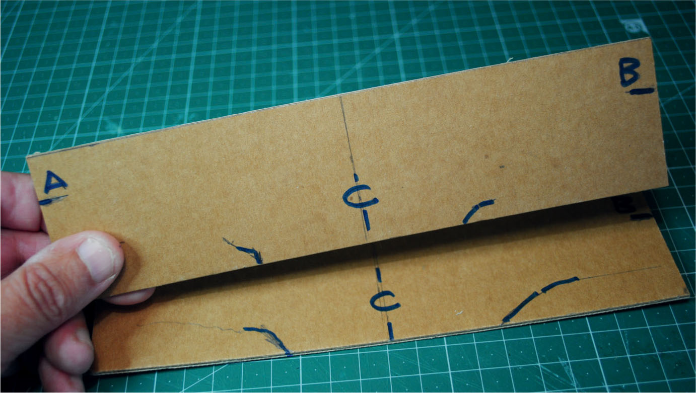
A five-bar farm gate is needed at the entrance to the field. Various styles are found in different parts of the country, but all feature five bars or horizontal rails. Pre-made examples for the model market are available in most scales. As this diorama has been put together in 1:43 scale (7mm to the foot), a five-bar gate from S&D Models could have been used, but this is an opportunity to show how a scratch-built gate of this type can easily be fashioned from scrap card.
To construct the gate I first made a scale drawing in pencil with the aid of squared paper and then went over this with a fine pen, filling in between the lines. The drawing was then glued down to a piece of foamboard or any other soft core material. The next task was to cut strips of card about 2.5mm wide from 1mm thick packaging card. The strips need to be cut longer than you need to start with, as they will be cut to size later during assembly. Another strip 3mm wide should then be cut from the same card; this will form the upright stiles.
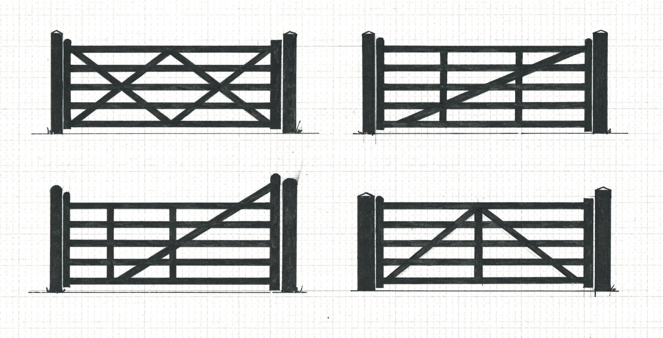
The various styles of five-bar gates, drawn to 1:43 scale and used as a template for the construction of the model farm gate.
A photocopy of the illustration was used to cut card strips for the five-bar gate. Note the use of double-sided tape to hold the strips in position while construction takes place.
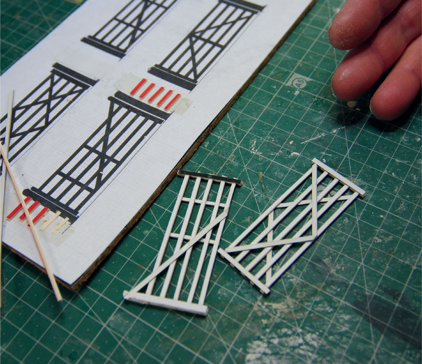
Two different styles of gates constructed using card strips. Note how the strips have been left over and cut away for the finished gate to be released.
When all the component strips have been cut, the gate can be assembled over the drawing, first placing two strips of double-sided tape on either side of the drawing close to the end uprights. The backing can now be peeled away to expose the tack. Each of the cut strips for the horizontal bars can then be positioned over the drawing, with the excess attached to the gummed surface of the tape.
With the five crossbars now positioned, the end uprights can be fixed and glued to the bars, followed by the angled stretchers. When applying the glue, this should be done in small dabs applied with a cocktail stick or similar, otherwise the card strips are likely to become glued to the drawing underneath. Up to this point only the facing side of the gate has been assembled.
Leave the assembly for the glue to bond, then cut away the excess from the bars, making sure that they are cut right up to the outside edge of the uprights. The assembly should now come free of the double-sided tape. Turn the gate over and place it over the drawing in order to add the uprights on the ends and the angled stretcher braces on this side. The gate can be made secure for this by placing dressmakers’ pins against the edge of the assembly and pushing them into the foamboard underneath.
The gate is completed by adding strap hinges and a latch. The straps to the hinges can be made by cutting thin strips of card with bolt heads pressed in, using an embossing tool. For the hinge part itself, a small length of styrene rod can be superglued at the end of the strap. The latch can be fabricated from wire and very small strips of card; styrene rod can be used as an alternative to the wire.
The five-bar farm gate can now be fixed or hung within the gate posts in a closed, open or slightly open position. The posts for this diorama were simply made from spent rocket sticks, which were carved at the top to resemble a shallow pyramidal shape. Both the posts were cut to length, allowing 5mm at the bottom for sinking it into the foundation scenery. The only remaining tasks were painting and weathering. Most gates out in the open countryside are soon weathered by the elements. The timbers are bleached to a silver grey colour or, if shaded by trees, they are turned green by algae.
The colours were mixed from oil paints: Payne’s Grey, Naples Yellow and Titanium White for the bleached finish, and Sap Green with a little Naples Yellow added to replicate the algae-covered gate. Photographing farm gates in the field will offer an understanding of how they weather and often become a host to lichen growth. All of this can be added in miniature to give more convincing results.
MODELLING THE DITCH
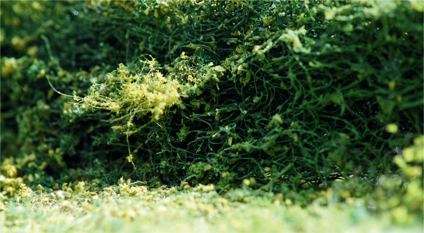
The banks, which had already been carved to shape in the insulation foam, were given a coating of plaster filler mixed with PVA. Both the banks and the bottom of the ditch were then painted with an earthy colour, comprising Burnt Umber mixed with Yellow Ochre. The banks were then again coated with PVA before a number of scenic materials were inserted into the glue, starting with the static grass. This was closely followed by adding clumps of teddy bear fur and a mixture of flock for the weeds and rough vegetation. Other vegetation was made from small pieces of sea moss with flock and other scatter materials added to provide the foliage.
The water in the bottom of the ditch was created by brushing on a couple of coats of clear picture varnish. Once this had dried a few marginal sedges and reeds were added using the bristles from old paintbrushes. I also added some fallen tree debris, both in the water and at the edge of the bank, to make it look more authentic. Photographs taken earlier showed that all sorts of debris can end up in a ditch, especially after a storm, or may have been deliberately dumped there.
MODELLING HEDGES AND TREES
The hedges bordering the lane were modelled using rubberized horsehair, first by cutting it away in strips from the supplied block and then teasing it apart. The hedges would be unkempt and wild in appearance. The horsehair was glued down before being lightly sprayed with a light green acrylic spray paint. While the paint was still wet, various colour shades of flock were scattered on, together with brown sawdust or catkin bracts, to represent the dead foliage within the hedge. Both the sawdust and the flock were then placed around the base of the hedge to replicate fallen leaves and weed growth. Other evergreen species of plant life, such as ivy, were also added to complete the hedgerows.
The hedgerow has been constructed using rubberized horse hair, which was spray painted and covered with fine flock.
Close-up of the hedge running up to the gateway into the field. Flock has been added for the hedge’s foliage and the weeds building up at the base.
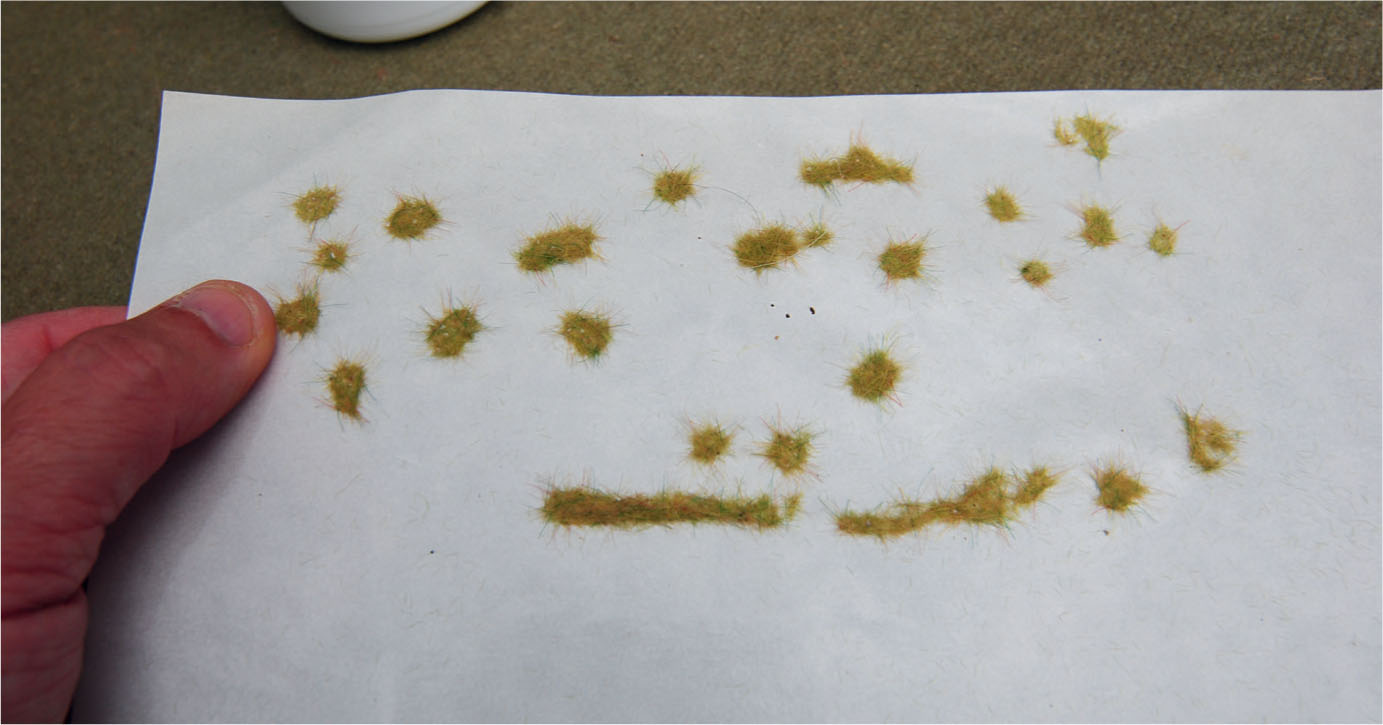
Making grass clumps using the grass applicator. The process requires placing small blobs of PVA on greaseproof paper. The fibres will then stick only to the blobs of glue and be repelled by the greaseproof paper.
Close-up view of one of the grass clumps used against the gate post. This also illustrates the painting and weathering of the five-bar gate, together with the build-up of weeds in this area.
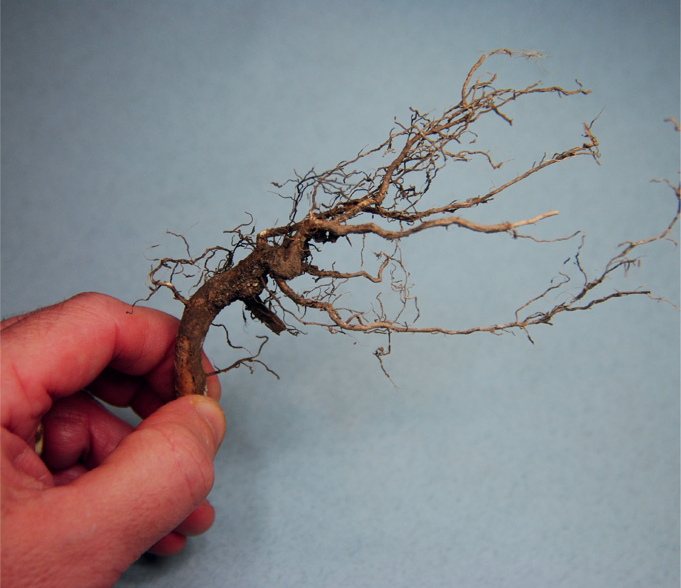
A piece of root selected for the dead tree that will feature on this diorama.
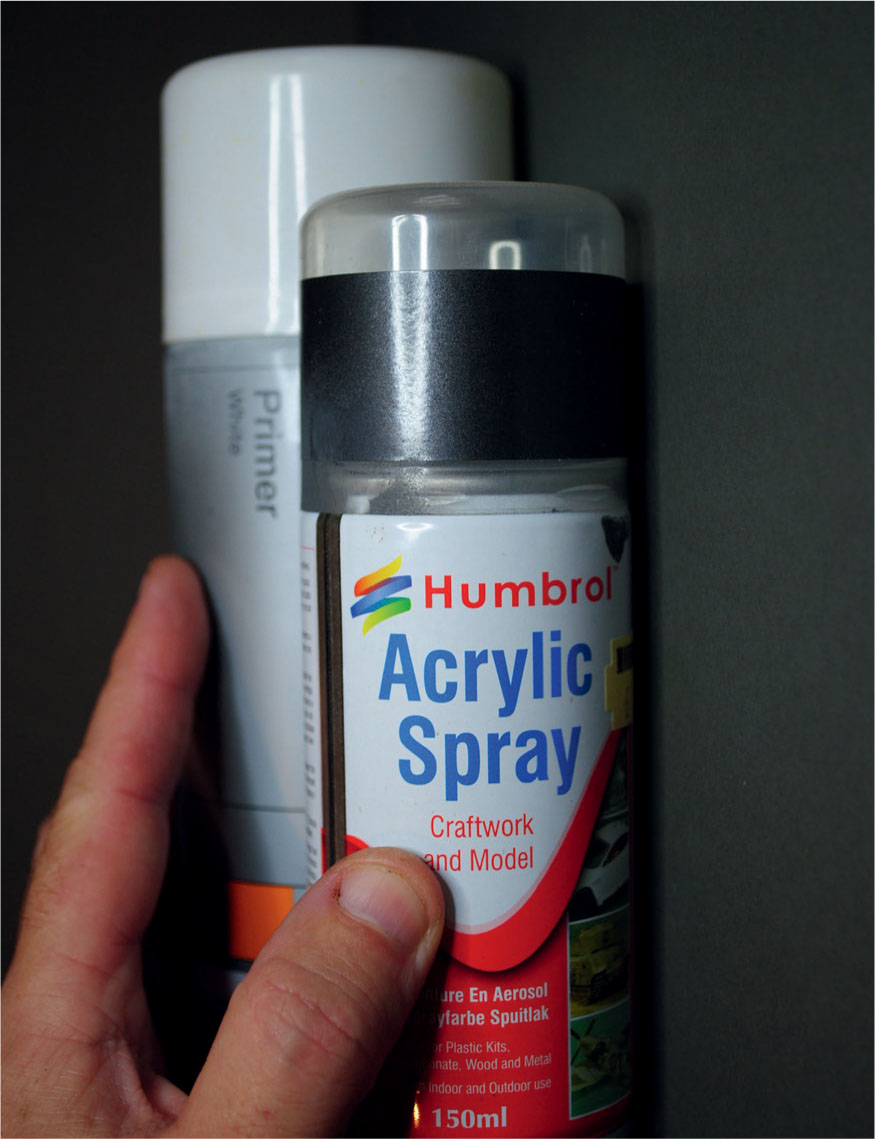
The diorama also called for a couple of trees. The first was positioned within the hedgerow and overhangs the farm gateway. The tree was made by gluing together selected sprigs of sea moss and coating them with PVA to bulk up the sprigs. The sea moss was then lightly sprayed, first with Matt Tank Grey and then with a Matt Olive Green, both from the Humbrol range of acrylic sprays.
The next task was to add foliage to the tree by first spraying the sea moss with spray mount. Flock matting from Woodland Scenics could now be draped over the twigs and shaped to resemble the foliage seen on this type of tree. The same flock matting was placed around the trunk of the tree to represent ivy growing up and through the lower branches.
The second tree growing from the banks of the ditch had seen better days. This tree was almost dead, just hanging on to life. To represent a tree in this state, I found an old root that was ideal due to its form. This was sprayed first to preserve it using a matt picture varnish, before being planted into the bank of the ditch, taking advantage of the root’s shape at the bottom. By careful positioning it was possible to make it appear that it was growing naturally from the side of the ditch.
The dead tree positioned on the banks of the ditch. Note the marsh grass and tree debris in the water of the ditch.
The dead tree in the foreground and the tree added to the hedgerow are seen here, together with the entrance to the field and the gate.
Since the tree was nearly dead only a small amount of foliage would be required. A few pieces were teased away from the flock matting and attached to the twigs in appropriate places. Again photographic reference came from photographs of dead or nearly dead trees.
To complete the tree more flock was added around the base, together with ivy growing on the lower dead wood. The flock on the matting was also used again on the hedges and for the rough vegetation found on the verges, putting the finishing touches to a convincing rural scene.
Photographic reference, as used for this dead tree and the growth of ivy creeping up it, can be used when replicating details in miniature on the diorama.
This photograph provided the detailing necessary for the model of a larger tree in full foliage, growing along the hedgerow. Here too ivy can be seen growing among the lower branches.
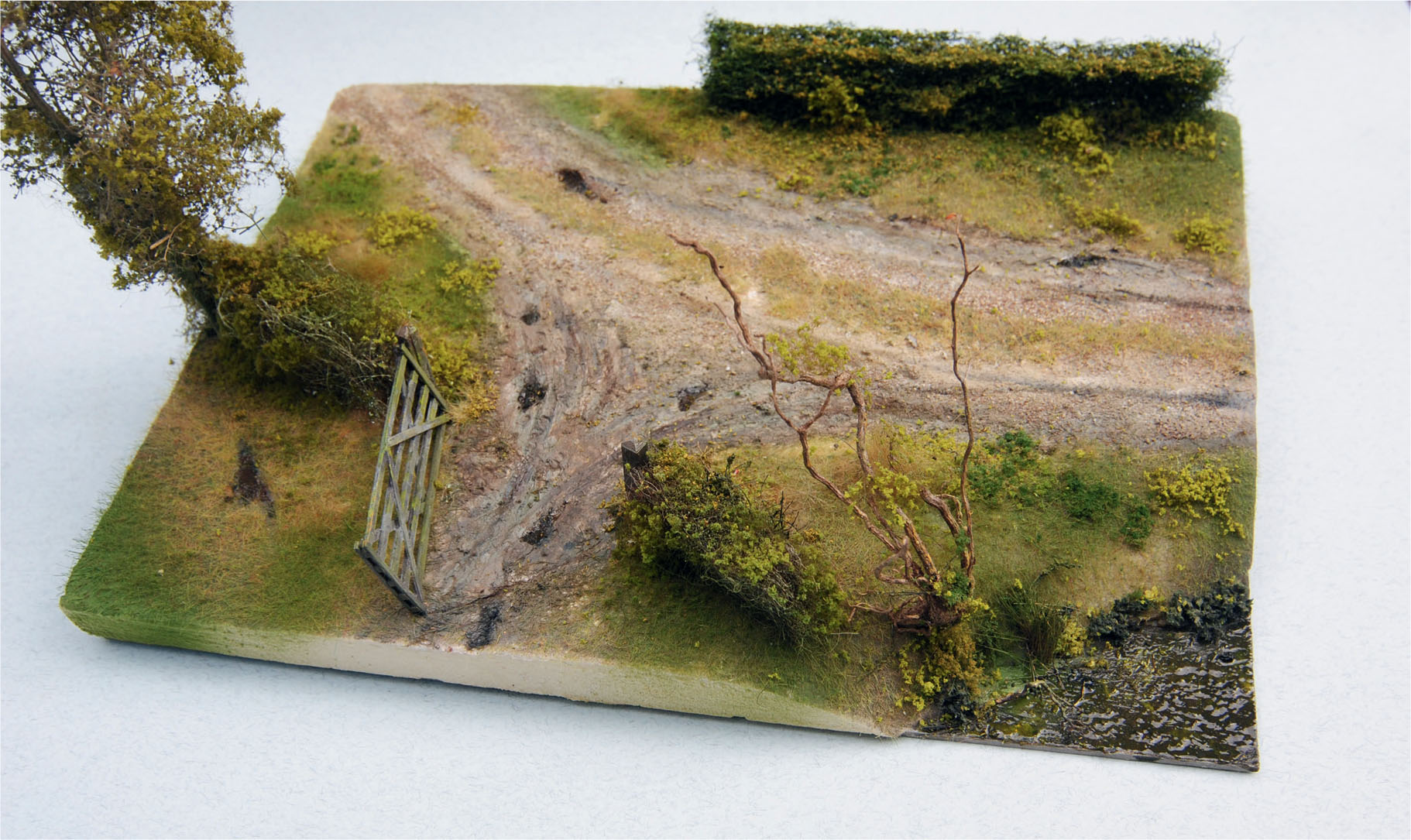
Overhead view of the finished model lane diorama, showing that a reasonable model of a rural scene can be made with inexpensive materials.
PROJECT 2: MODELLING A FROSTY RURAL SCENE
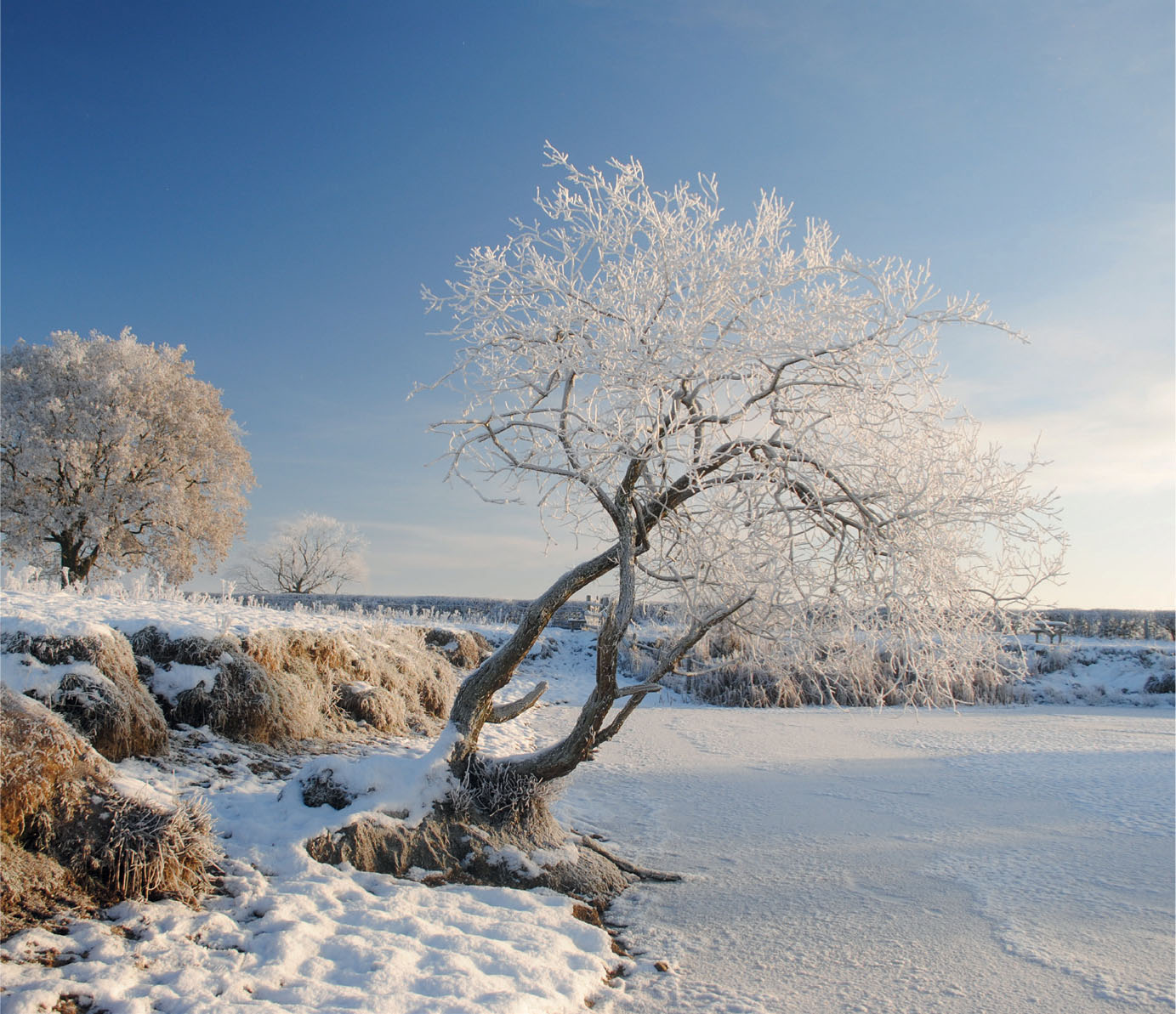
Earlier in this chapter I discussed how the seasons affect the rural landscape of the British Isles. In winter we regularly wake up to clear days when high pressure is prominent and the air is still. On those days an icy frost will soon develop, creating fine ice crystals that form on every surface, giving that distinctive white all-over covering. If the weather conditions create a mist in the air, then a much more impressive frost will appear with larger crystals forming a winter wonderland, known as hoarfrost.
Modelling winter scenes is usually confined to Nativity scenes and other Christmas-themed dioramas, which tend to feature snow on the ground rather than frost. Railway modellers on the whole, however, seem to prefer the warmer and greener seasons of the year, rejecting winter scenes.
I have therefore presented a modelling project that can be used as part of the landscape for a model railway or just as a simple diorama. The model features a pond in the foreground, with marginal plants such as reeds included at the water’s edge. An old dead tree is modelled with fallen branches entering the pond. Ivy is growing prolifically on what is left of the trunk.
Various types of undergrowth and scrub have been modelled leading up from the banks of the pond to the rough grassland above. The boundaries are marked by an unkempt hedge, comprising a mix of vegetation and a small tree, and by a dilapidated post and rail fence that has seen better days, with ivy clinging to the timbers and holding together what remains.
MATERIALS AND MODELLING TECHNIQUES
The starting point for the model would be the face of the baseboard. For the diorama I used a small panel of Daler Board, an oil-primed board intended for artists that comprises a heavy-duty card faced with canvas. This was ideal as it was both strong and light, with the advantage of a textured surface. For the land I simply used polystyrene salvaged from packaging. This was glued down in two layers to form the lower ground and the higher ground towards the back, before being carved with a hacksaw blade to create the contours and the banks to the pond. With the carving complete, the polystyrene was lightly sanded before being coated with a watered-down PVA to help seal the polystyrene and give the land more stability before painting and adding the grass and any other vegetation.

The effect of frost on long grass was one of the aims for this model.
Once this was dry the painting could begin. An earthy colour was mixed in an old ice-cream tub using Burnt Umber, Payne’s Grey and Yellow Ochre acrylic paint from the tube, as this would dry more quickly than oil paint. A liberal coating was then applied over the land. A similar mix of paint, omitting the Burnt Umber, was made up to give depth to the pond.
Once the paint had dried on the land areas the grass could be added. Most of this was static grass, using different lengths of pre-coloured nylon fibres loaded into a static grass applicator. The land area was then given a coat of PVA glue. While this was still wet and tacky, a pin was connected to the earth wire of the applicator, creating a static field. The applicator was then switched on and shaken over the area, allowing the charged fibres to drop into the glue and stand on end away from their nearest neighbours. This process gives a very authentic replication of grassland, but more needs to be done if rough grassland is required.
The paint mixture mentioned above was then applied to the pond to give it some depth. A few products are available to represent the surface of the water, but a cheaper alternative is to use gloss picture varnish by Winsor & Newton, which is perfect for creating the surface of still water. The varnish was then applied using a half-inch (12mm) filbert brush, taking care at the edge running up to the banks. A couple of coats of varnish should be applied evenly, allowing each to dry before applying the next one.
The marginal plants could now be added, starting with the reeds. A mixture of materials was used, although most were fabricated from the bristles of an old paintbrush. Other reeds and marginal plants came from scenic materials in the Green Scene and Woodland Scenics ranges. Flock material was also used to create the rough foliage found on the upper grassland area. A dead tree was added to complete the banks of the pond, using part of an actual tree root that had the perfect knarred look to represent an old tree’s dilapidated state. The natural colour of the root was also perfect and there was no need to add any paint, although the effect of ivy growing over what was left of the tree was created scenic materials from the Mininatur range. To complete the appearance of the tree, two pieces of the root were cut off to replicate branches that had broken away and fallen into the pond.
The two boundaries were modelled next, starting with the hedgerow. For this a strip cut from the block of rubberized horsehair was roughly shaped using scissors into an irregular shape representing a hedge that has not been maintained. The strip was then glued into position, before various flocks were inserted under and around the base to represent the weeds and undergrowth typically found under a hedge of this type. Some scatter was also added to represent the dead and fallen leaves that accumulate under the hedge. When modelling a hedge in winter, however, there is no need to add flock to the bulk of the hedge except for ivy and the other parasitic species usually found growing there. By using a spray adhesive, small pieces of ivy, again from the Mininatur range, can be draped randomly across the horsehair.
Some height can be added to the diorama by modelling a small tree growing within the hedgerow. This may be fabricated using a sprig of natural seafoam, available from suppliers including Green Scene and Gaugemaster Scenics. The foam gives a good representation of a small tree without requiring too much extra work, although any seed pods found will need to be carefully removed. The thicker stems can be given a coating of PVA and plaster to bulk them up and make them more stable. This will require painting afterwards, but the natural colour of the seafoam can otherwise be left untouched. Once this has been glued in position within the hedgerow, a little ivy may be added creeping up the tree.
Close-up of the lower part of the hedge, showing the materials used and the finishes applied to create a covering of frost.

Another close-up, this time showing the construction of the rustic fence and the spray-painted frost covering it.
The completed diorama with the iced-over pond in the foreground and the banks with a dead tree, together with the marginal scrub. The grass, hedges, tree and fence are all visible. To replicate a frosty rural scene, the diorama has been given a spray paint finish with a dusting of Icy Sparkles from Deluxe Materials.
The other boundary consisted of a rickety old fence, using strips of veneer for the rails and spent rocket sticks for the posts. These are examples of scrap materials you might be able to recycle for use in your modelling.
The posts were first cut to length before being positioned roughly in line, keeping most of them upright. The inclusion of at least one post leaning at an angle will make the fence look more authentic. The rails were then made by cutting the veneer into strips roughly 2–3mm wide. These can then be cut or broken to the lengths required, before being glued to the supporting posts. Having one fixed so that it falls away at an angle will make it look more rustic. You will also notice that the rails extend over the pond. The original purpose of this was to stop livestock straying around the end of the fence and entering another field.
The fence was then painted a light grey colour to represent old timbers bleached by sunlight, although a little green was included in certain areas of shade where algae had grown on the surface. As with the hedge and tree, a small amount of ivy was spray mounted to the fence in order to complete the rundown, rustic look.
ADDING THE FROST AND ICE
With the construction now complete, attention turned to transforming the scene into winter. The process was started by creating the ice covering the surface of the pond. Equal quantities of PVA glue and water were mixed together and then two coats were brushed over the varnished surface of the pond, being very careful to paint up to the marginal plants and around the fallen tree branches. This was left for a few hours until a flat, rubbery skin formed all over the surface of the pond.
The two main spray paints used to create the covering of frost are Gunmetal from the Humbrol military range and Halfords White Primer.

To complete the wintery feel, a light sprinkling of Icy Sparkles was added all over.
A little magic is required to turn the thin, semiclear skin of the pond’s surface into realistic-looking ice. This was easily created by using a few cans of spray paint, starting with Gunmetal from the Humbrol Military range, followed by a light coating of Ford Glacier Blue from the Halfords range of car body spray paints. A top coat of Halfords White Primer was also sprayed all over. Don’t be worried about any over-spray straying over the fallen branches or the marginal plants on the banks of the pond, because everything else on the diorama will require the same treatment with spray paint. If this is followed correctly it should result in a good replication of a heavy frost covering. To make this even more convincing, some Icy Sparkles from Deluxe Materials were sprinkled over the whole diorama to give the icy glint that completes the effect.
The very last process was to create the effect of cracked ice, especially around where the fallen branches entered the pond. A sharp scalpel blade was used to scratch through the painted PVA skin in some places and then carefully peeling away the skin to reveal the water beneath. I would always recommend taking photographs of cracking ice before trying to replicate the effect on the model. If you are unsure of what to do, make up an ice panel and practise on this before tackling the finished model.
A pond has been chosen for this diorama project, but the same techniques can be used to create an ice covering over any still water, whether it is a pond, lake or even a canal. It is always worth having a go. I am sure you will agree that a winter scene can make a refreshing change on a model railway layout or a military diorama.
PROJECT 3: CREATING A FAST-FLOWING RIVER DIORAMA
Before starting on any diorama, we must first decide what to use as the base, as this will provide the foundation on which the whole model is constructed. An offcut of chipboard was chosen for this project, but plywood or a fibreboard such as Sundeala would also be acceptable. Extra pieces of chipboard were glued down to create the higher levels needed for the waterfalls and the weir. For these, one edge was cut at an angle of around forty-five degrees.
The next job was to build up the banks and make the foundations for the bridge and the watermill, both of which would be major features on this diorama. Strips of foamboard were used for the foundations of both and to create the shaped profiles required to support the landscape running up to the riverbanks. A web was then created using the traditional method of card strips, before a covering of plaster bandage was added over the top. Once this had completely dried out, a wash of oil paint was brushed all over the plaster. For this an earthy colour, produced by mixing Burnt Umber with a little Yellow Ochre, was applied with a large filbert brush.
CREATING THE RIVERBED
Before moving on to the river itself, it is always advisable to take time out observing and photographing fast-flowing rivers for future reference. In my case it became obvious that it would first be necessary to create the riverbed. Sand and fine grit ballast from the Woodland Scenics range was scattered over the required areas. This was glued in place with diluted PVA using the same method employed when ballasting track, which involves first wetting the grit and ballast with an indoor plant mister before flooding it with diluted PVA. Small rocks were next glued in, mainly around the waterfalls; grey cat litter was used for these. Larger rocks were added using small flat stones collected on walks. Even larger rocks were fashioned from tree bark, which gave a good representation of the river’s rocky sides.
The next task was to paint the riverbed, again looking at prototypes and photographs before making a start. A mix of Yellow Ochre and Burnt Umber was made using artists’ oil paint, before creating a wash with a consistency of 20 per cent paint to 80 per cent white spirit. The wash of colour was brushed over the riverbed, allowing the thinned-down paint to flow into the grit and around the exposed stones.
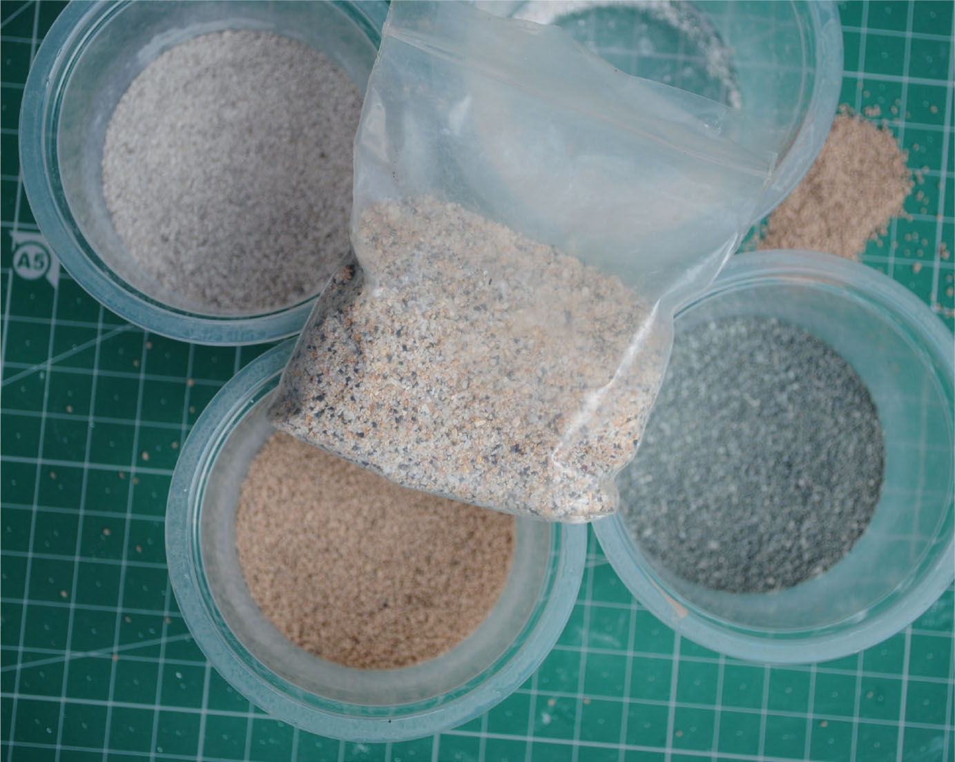
A selection of the sand and grit used on this diorama. Most will be used to create the riverbed, while some will be used for the lane surface.
The main colours to be used from the tube as base colours for the diorama. Raw Umber and Yellow Ochre mixed together give both the ground colour and the riverbed.
The riverbed will require a wash of the colour, made by mixing the paint with plenty of white spirit.

The ground colour is mixed in a tub only using a small amount of white spirit.

Plaster bandage is used to create most of the landform for this model diorama.
The riverbed and the cobbles of the ford, scribed in the clay, are painted over with a wash of paint.
Sand and some smaller rocks have been added to a coat of PVA painted over the riverbed.

A selection of small and larger stones, cat litter and tree bark are added to the riverbed to rocks and the rocky banks.

PVA is used to glue the stones and rocks in position.
The rocks and smaller stones are here seen fixed to the riverbed and the sand has been painted over again with a wash of paint.

Painting the wash over the sand on the bed.

The rocks in the bed and to the side of the upper waterfalls are here seen in close-up.
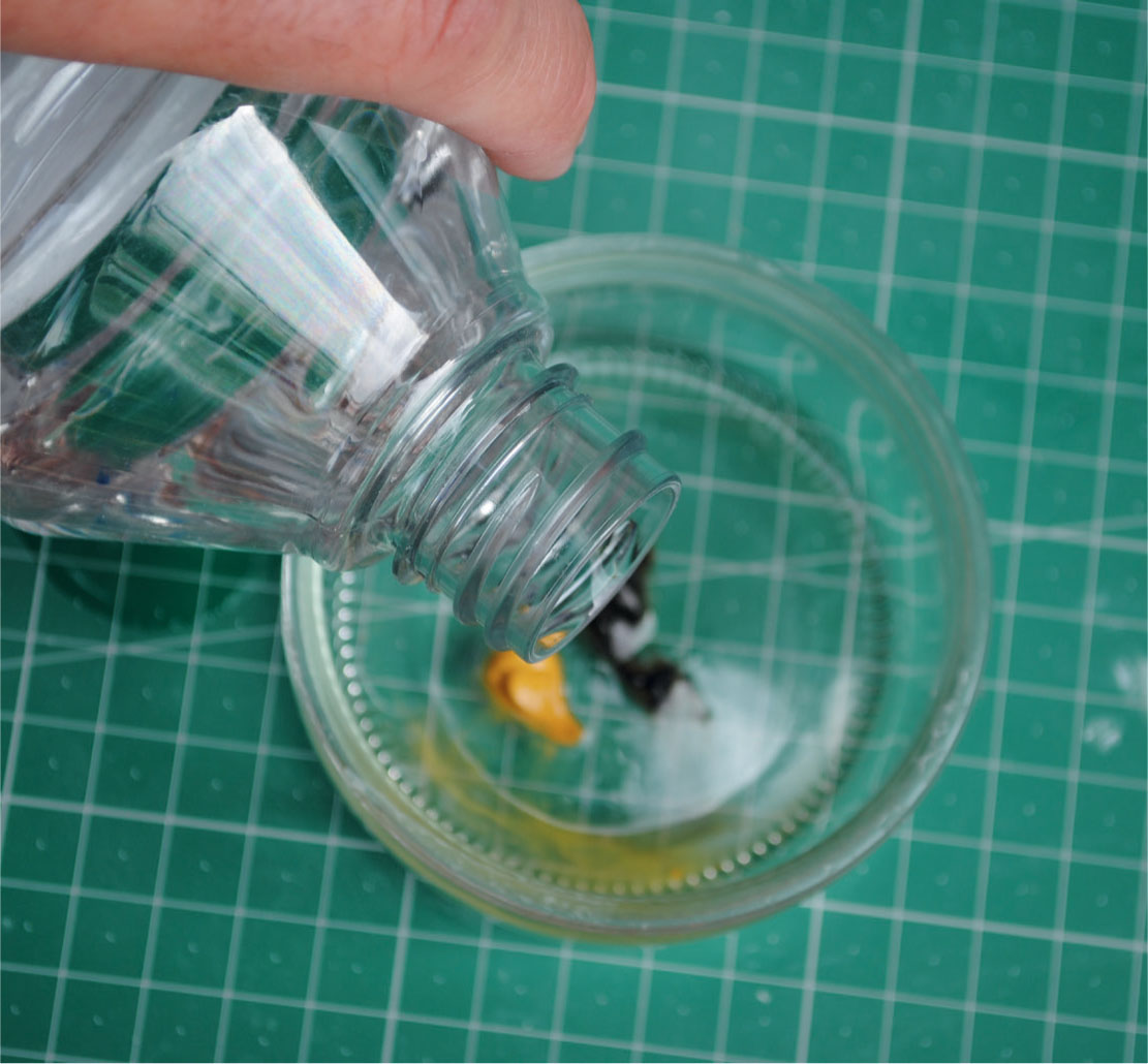
At this consistency the paint was soon dry and the bed was ready for the next important stage, creating the actual water. In the past I have used polyurethane gloss varnish for the water, but for this project I decided to try a relatively new product on the model market, Solid Water from Deluxe Materials, which is intended to simulate crystal-clear water. The two-part kit contains a resin, a hardener and two measuring beakers. It is recommended that you measure two parts of the resin to one part hardener. It is important to ensure, however, that at no point are the liquids cross- contaminated.
Following the instructions, the two parts were mixed together, stirring with the supplied spatula until the mixture was no longer streaky and making sure that no air bubbles were formed. Once the desired consistency had been achieved, the clear mixture was carefully poured onto the riverbed, spreading it into all areas with the spatula. Particular attention should be paid to spreading the resin into the tight gaps around the exposed rocks.
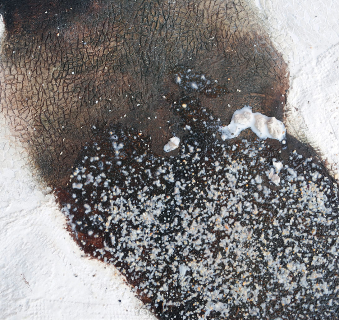
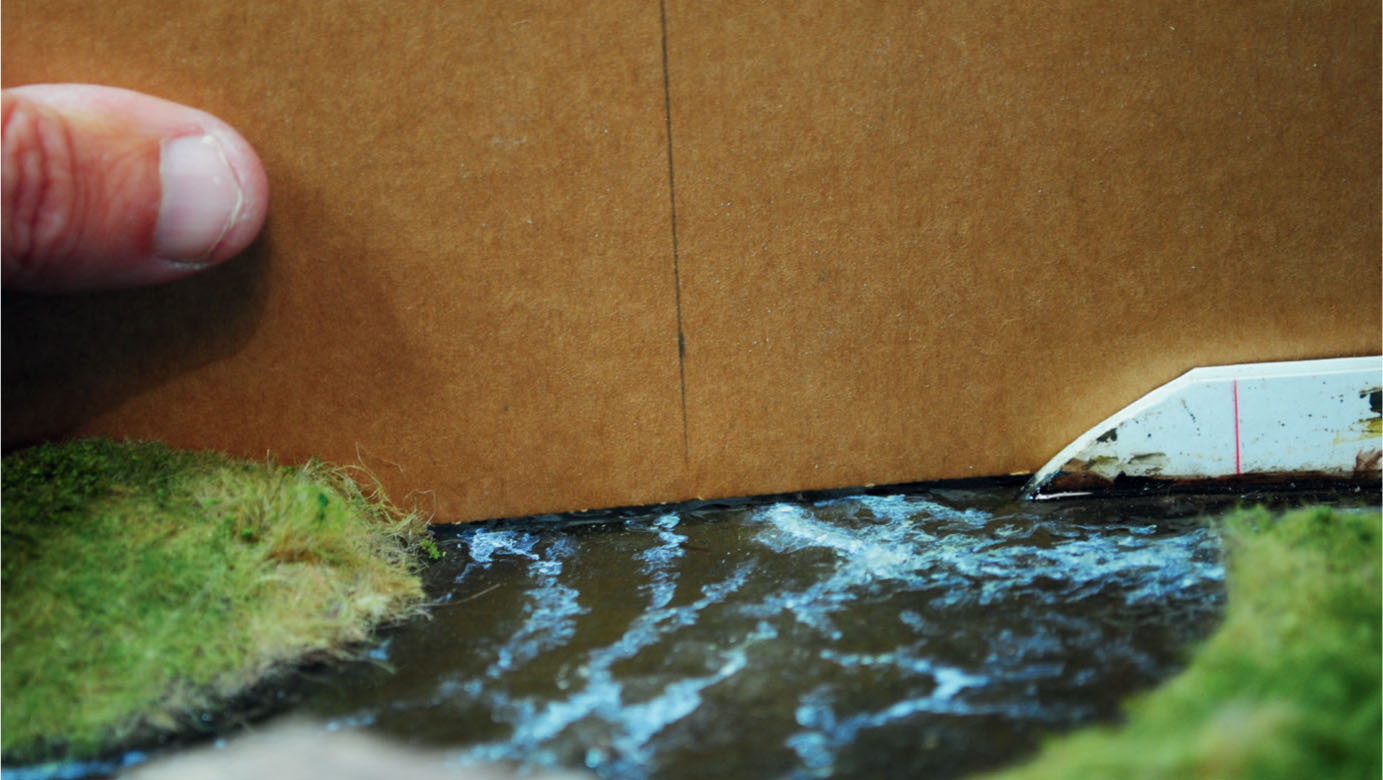
The clear resin was then left for five hours to set a little. In order to create a ripple effect on the surface, the spatula was dragged through the resin where required. The consistency of the resin at this stage resembled treacle toffee and it took a few attempts to achieve the ripple effect. More dragging was concentrated around the bottom of the weir, where the water turned over. Digging into the resin with the spatula and then turning over the surface resin resulted in a reasonable representation. Well before the resin has completely hardened a start should be made on adding the white water, using Titanium White artists’ oil paint thinned down with white spirit. The paint was applied on the surface of the resin using a No. 1 rigger brush, making sure to follow the direction of the flow. The oil paint feathered out within the resin, resulting in an authentic impression of the white bubbles that are seen just below the surface. More of the white paint was added when the resin was completely hard in order to replicate the white water on the surface.
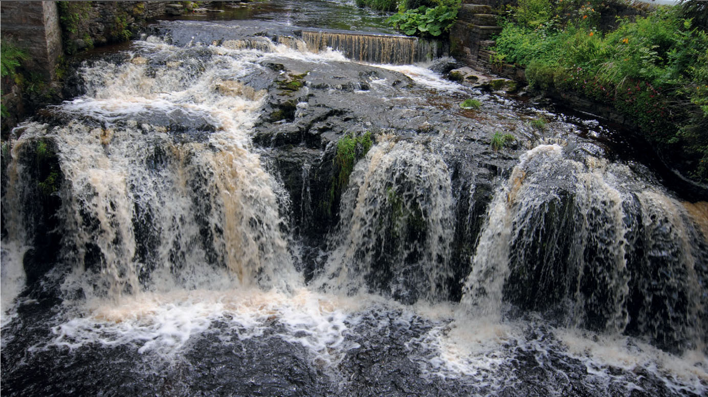
The white water on the River Dart provided the prototype inspiration that this model diorama attempts to replicate.
Once the clear resin was dry it was time to paint the white water starting with the waterfalls, making sure that the direction of flow was addressed.
CREATING WAVES
To complete the white water effect I experimented with Making Waves, a one-part resin that is also available from Deluxe Materials. Although the makers recommend it for creating waves, ripples, waterfalls and moving water effects, indicating that it should be ideal for this project, unless you are carful it would be easy to overdue these effects. After consideration I decided to use it just for building up the waves around where the water was breaking around the exposed rocks, the waves at the bottom of the weir as they turned over, and the point where the two flows of water clashed. The makers recommend using a syringe to build up thin films of the resin before shaping. I found, however that I was more confident using a fine paintbrush, which gave more control. The layers could be built up in just the same way, shaping the waves again with the brush. The resin dried quickly and the fast-flowing river, with its waterfalls and the weir, was soon complete. The successful results showed that the experiment had paid off. Making Waves would be considered again when it came to fitting the waterwheel to the mill. By coating scenic fibres with the resin, the run-off from the wheel could be achieved with realistic-looking results.
FORMING THE RIVERBANKS
The next stage was to shape the riverbanks and add marginal plants as detail. The first task was to paint the white plaster bandage with an earth colour to represent the soil. This was achieved using a wash of oil paint. For this I again made a mix using Burnt Umber and Yellow Ochre, but the soil colour may differ depending on your location. If you are modelling somewhere in South Devon, for example, you will have to mix a colour to represent the red soils found in this area, so replace the Burnt Umber with Burnt Sienna.
The next task was to make a start on adding all the grass growing on and around the banks. Wild grass tends to grow in clumps, so I would advise using various materials and mixing them to achieve something like the real thing. The first material used was carpet underlay felt (a hanging basket liner could be used as an alternative). The felt was cut into strips and then into small blocks. At this stage it is important to separate the block from any nylon webbing that may be holding the fibres together. Try to make sure that the fibres are all in the same direction, so that the felt can be planted end-on into a bed of PVA. Repeat this exercise until the desired area has been covered with the fibres. This will take a while to complete, but this method ensures the grass will appear to be growing in clumps, replicating real wild grass.

The carpet underlay felt was cut into small pieces, keeping the fibres in one direction.

The clumps of carpet underlay felt were glued down using PVA, following the . prototype reference as closely as possible to replicate the rough grass.
Oil paint was selected again to colour the felt. A reasonable representation of the shades seen within grass can be achieved using Sap Green, Lemon Yellow, Yellow Ochre and Titanium White.
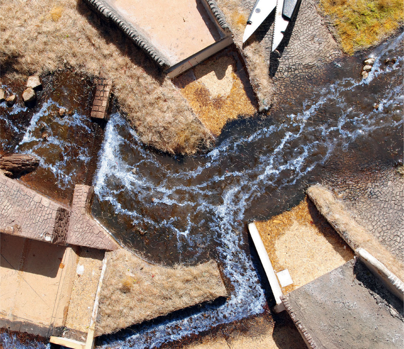
An elevated view showing the river with the white water added. The carpet felt on the left-hand side has not been painted, while that on the right has been painted with a wash of shades of green. The ford and the foundations for the bridge may be seen.
Once the PVA glue has completely dried, the felt fibres should be painted with oil paint, mixing Sap Green with Yellow Ochre and thinned with good amounts of white spirit to create a wash. This was then applied, letting the paint flow through the fibres. I also added Lemon Yellow and Titanium White to the colour mix to brighten the grass shade in places.
The longer grass was next created using teddy bear fur. This was cut away from the backing and planted again into a bed of PVA glue. As the natural colour of the fur resembled the dead dry grass perfectly, this was left unpainted. More grass was added using the static applicator, this time choosing Summer Green nylon fibres, available in short, medium and long lengths, from Green Scene. Mixing materials in this way gives a more natural-looking result.
To finish the rough grassland, weeds and other vegetation would need to be added. To create these in miniature, foam flock from the Woodland Scenics and Javis Scenics ranges were chosen. Selecting the smaller clump material and varying the green colour gives a more natural appearance. Weeds tend to retain their green foliage throughout the winter months even when most of the grass has died back to a straw colour. Look at how the weeds grow and try to replicate this realistically when fixing the flock into position with spray mount glue. It can be tempting to overdue the use of foam flock, so keep referring to reference photographs.
A few marginal plants will be needed at the river’s edge, so again look where and how these grow. Many plants come into this category, ranging from flat water lilies to tall bulrushes. Plenty of reference for the diorama was found by photographing plants growing on the banks of the rivers in my home county of Derbyshire. Species such as Butterbur, together with various reeds and sedges, were found in abundance. It was now down to finding materials to replicate them.
For the Butterbur, which has distinctive rhubarblike leaves, I found some old foam rubber carpet underlay, which looked very much like the plant when torn and shredded. The foam rubber was glued in position using PVA and then painted with a shade of green to match the photographs. The taller reeds and sedges seen growing in the still pools could be modelled using some of the long fibres provided by the scenic suppliers, but this was an opportunity to salvage an old paintbrush that was ready for the bin. The worn-out bristles resembled the reeds perfectly, so a few were cut away and planted into the pools above the weir and below the ford. The bristles were finished by painting them the correct shades of green.
The river and water features were now complete, together with all the immediate scenic modelling required for the diorama. The next part of the project was to decide how to tackle the structures and the watermill, starting with the bridge.

The tail race of the mill has also been painted to offer more white water.

In this elevated view the grass has all been painted and the flow of the painted white water is clearly visible.
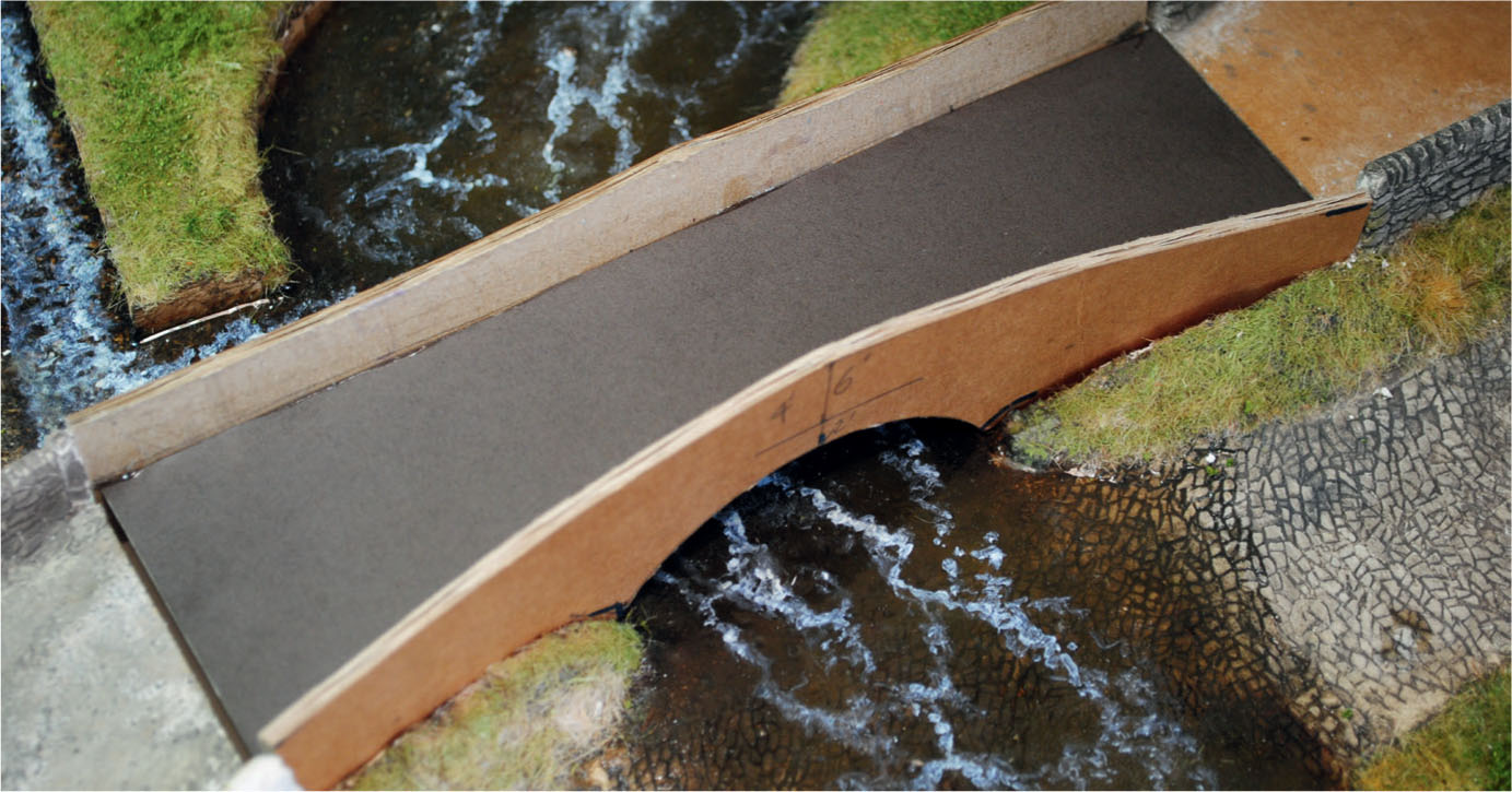
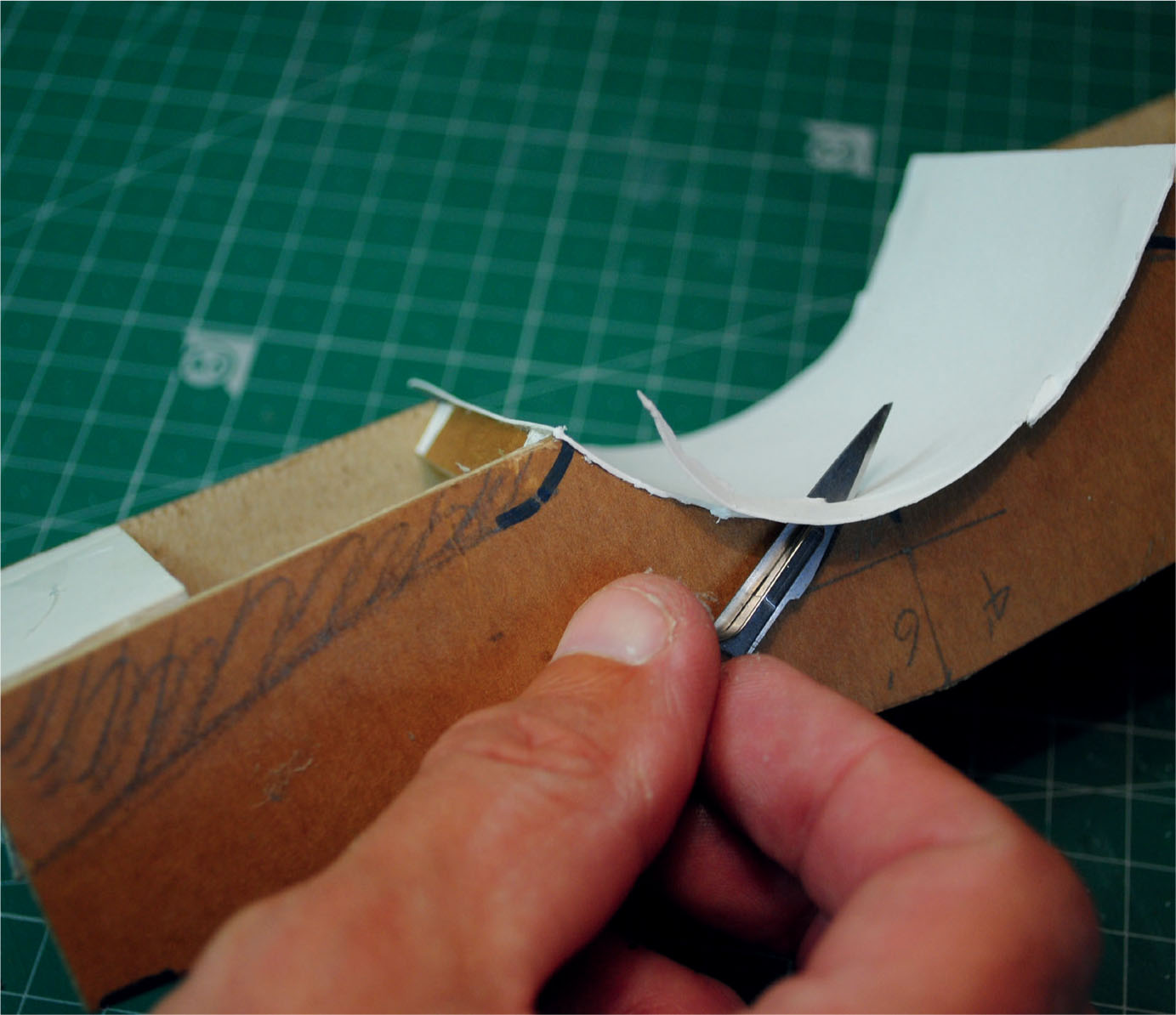
CONSTRUCTING A STONE ARCHED BRIDGE
Continuing the theme of this chapter, it was important that this diorama included a lane running down to the river, where a stone arched bridge was provided to make the crossing. Alongside the bridge was the ford that would have preceded its construction and now provided an alternative means of crossing the river.
With the foundations already fixed in position on either bank, it was now time to tackle filling the gap. After looking at the available materials, sturdy cardboard appeared to be ideal for this structure, with a skin of Das modelling clay added to provide the masonry. Photographs of single-arched bridges crossing the rivers Dove and Manifold for reference indicated that these had all been constructed using local rubble stone, which would be reasonably easy to scribe out in the Das.
Some strips of Corri-Cor board obtained as unwanted offcuts from a local picture framer were selected. This material is ideal for the construction of any small structure or building (and is free if you can obtain it in the same way).
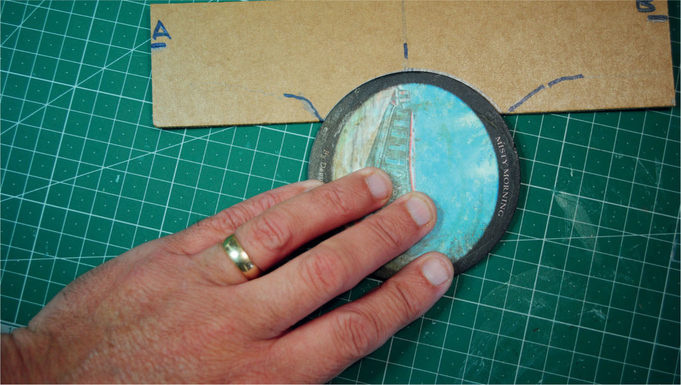
The card strips were first cut roughly to length using the gap left for the bridge as a guide. The card strip was now moved into position in the gap. Next the centre distance was plotted and a line drawn to mark this point. At the same time the profiles of the banks were marked with a felt-tipped pen, along with the estimated height to the top of the parapet walls at each end. With the banks now marked where they came down to the surface of the river, the arch of the bridge could be marked out. A slate drinks coaster was found to be just the right size to use as a template when cutting the arch, but if you can’t find anything similar, then try using a compass cutter. This was repeated on the card for the other side of the bridge, ending up with both arches cut out.
The prototype inspiration and reference for the single-arched bridge that will feature on the model diorama.
The strip of Corri-Cor board is cut to size and positioned, and the centre is then marked for plotting the arch.
Both strips for the sides have here been marked with pen, marking the position where the banks meet the surface of the river, together with ends of the parapet walls.
The next stage was to mark out and cut to shape the road deck. Thinner card was used for this as it would need to bend slightly to create the hump over the arch. Picture mounting card was used for this, once again acquired from the picture framer. The first job was to mark in the length and width of the lane at each end of the bridge, together with the narrower width at the centre. Once this had been plotted, the gentle concaved curve could be drawn using a flexible curve obtained from a stationer. The flexible curve can also be used as a template to cut against when cutting out.
Once this curve has been plotted the card sides will need bending to follow the same curve; this was the main reason for selecting this type of card. The two sides were then positioned temporarily so that the stretcher braces could be measured before cutting from 6mm balsa wood or foamboard. The stretchers, which are fitted at both ends of the bridge along the bottom edge, need to be the height of the lane at each end, less the thickness of the mounting card. The reason for this is to support the road deck as well as adding strength at these points. Other supports will be needed to hold the deck in position along the length of the bridge.
To create the hump, measure down from the top edge of the parapet, remembering to allow for the thickness of the mounting card, and make a small card template. Using this, the curve of the hump can easily be plotted and marked on the inside walls. The next stage is to cut small cubes of balsa wood, no larger than 5mm in size. These can then be glued to the underside of the plotted line, requiring about eight on each side. The card deck can now be bent to sit on the supports and glued securely in place.
A slate coaster was used as a template for cutting the arch. A compass cutter can be used if a template is not available.

Both arches have been cut out.
The two sides have been cut to shape and positioned temporarily within the pre-made foundations. Note that the sides have been slightly bent to shape.

With the sides curved to shape, the road deck could be made up using mounting card cut to follow the curves on each side.
The card deck has now been glued into position using small blocks of foamboard underneath for supports.
This view from underneath shows how more blocks of foamboard have been added to support the card that forms the inside of the arch.
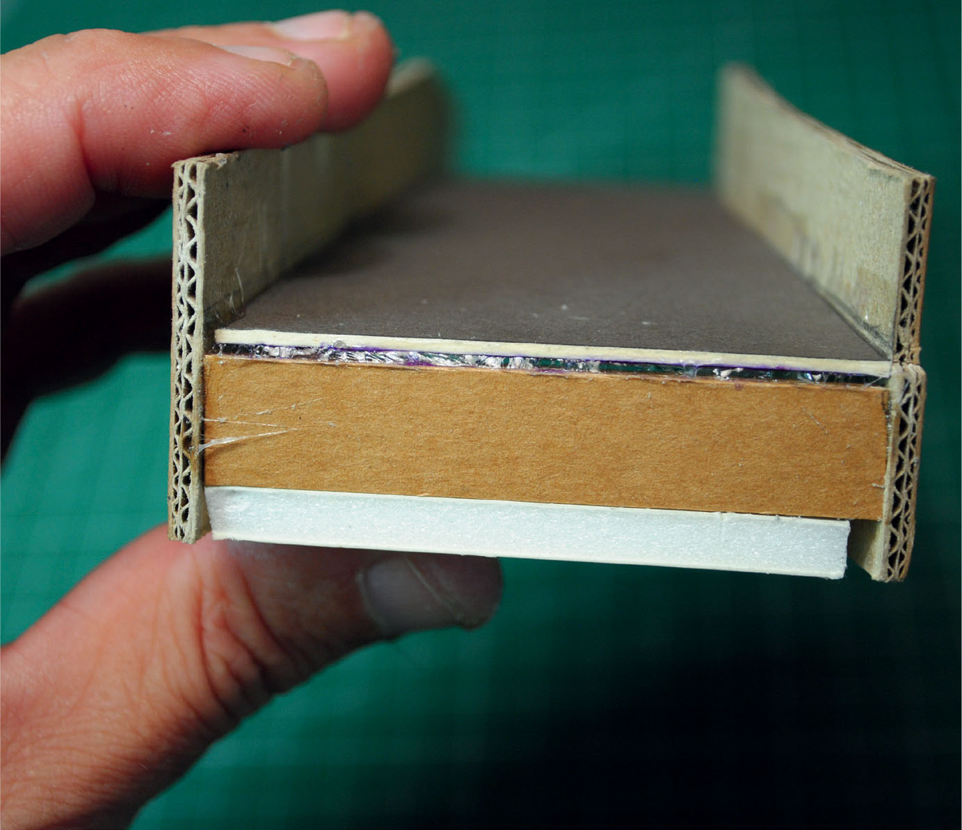
The two additional stretchers can be seen when viewed from the end. These will create extra strength as well as supporting both ends of the road deck.
The card inside of the arch has been roughly glued into position. The thin card, here cut from an old greetings card, will require curving to shape before fixing.
Once the glue has bonded, the excess card was cut away on both sides to give a neat finish to the arch.

The completed construction can now be positioned to make sure everything fits correctly. Note the coppings have been fitted using cut strips of mounting card.
The blocks can be also used to support the inside of the arch, this time fixing them to follow the edge. To fit the inside arch, much thinner card was selected from an old greetings card. This will need to be cut out oversize and then repeatedly rolled using a metal ruler until the curve to the card matches the curve of the arch. It can now be offered up to the model and any adjustments made to the curve, before gluing to the supports and edge of the cut arch. Once satisfied, the excess card can be cut away using a sharp scalpel, leaving a neat finished job.
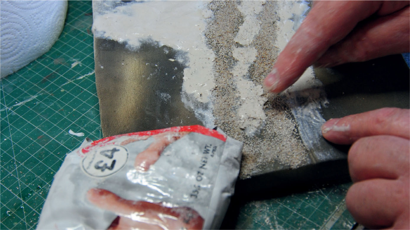
The whole bridge construction can now be tried in position to make sure everything fits correctly before moving on to adding a skin of Das modelling clay to all the outside walls and the inside walls on both sides of the parapet. The outside walls were attempted first, brushing on PVA and then pushing small amounts of Das into the glue. A reasonably thin skin can be achieved by using only a small amount of clay at a time and wetting the fingers when spreading. The thickness of clay added needs to replicate the stonework of the prototype, as well as the scale of the model. The clay was added to both sides and then to the inside of the parapet before being left to air dry for about twenty-four hours. The clay not only creates the texture required for the masonry but also makes the model strong and rigid.
The scribing out process could now begin, starting with all the keystones to the arch. It might be worth drawing in the depth by making a small card template again. This can be held up to the inside edge of the arch to plot the curve again, marking this in pencil on the bridge side. All the scribing would be done using a scalpel fitted with a 10A used blade, holding the scalpel with a finger directly behind the blade. It is important that the scalpel is held in this way as it gives control. If trying this for the first time, however, practise scribing stonework on a pre-prepared piece of scrap card before starting out on the model.
All the masonry has been scribed out, starting by drawing in and then scribing the keystones and voussoirs of the arch.

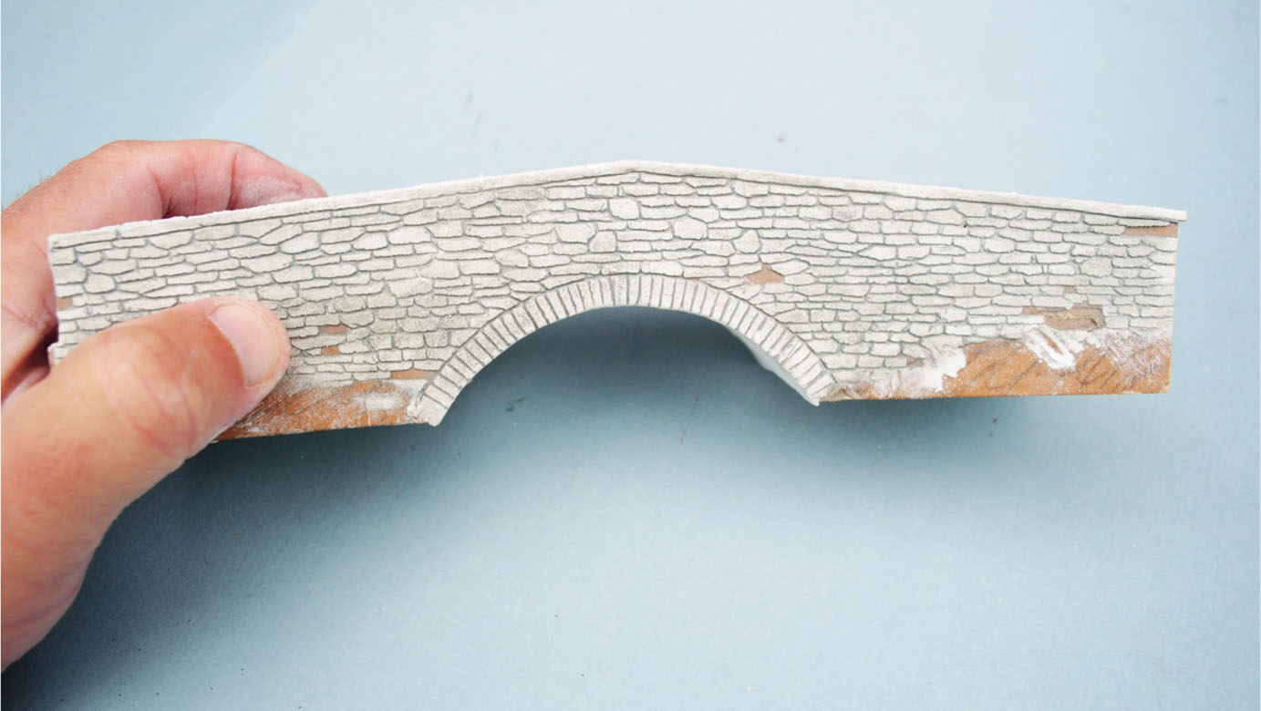
After the masonry has been painted and weathered, the bridge is now seen in place with the ford in the foreground.
The keystones can be followed by scribing all the rubble infill, making each stone a different size and shape. Always follow photographs of this type of stonework to replicate the prototype as closely as possible. Once the stonework has been scribed on both sides, the inside walls of the parapet will need scribing with the same masonry. Be careful here because the room to manoeuvre the scalpel will be fairly restricted.
The next task was to add the coping stones to the top of the parapets. For this small slabs of balsa wood or thick card can be used. A strip about 5mm wide was first cut and then divided into lengths of about 10mm. These were then glued one by one onto the top until the parapet was coped. Instead of using Das to give the texture, this time a thin coating of Unibond No More Cracks plaster filler was applied by brushing it on to the surface of the coping stones, with diluted PVA to create the bond. To finish, the same plaster coating was applied again by brush to the inside of the arch, giving texture and rigidity to the card.
Before moving on to painting the bridge, the road deck would also require some surface texture. This was executed by first brushing on some PVA and then scattering fine sand over the surface while the glue was still wet. The finished result resembled the gritty metalled surface common to most rural lanes. This surface, of course, would also be applied to the rest of the lane leading up to and away from the bridge. The approaches and base of the ford were made by using a thin skin of Das modelling clay with irregular cobbles scribed into it. This more substantial surface material was necessary to withstand not only the traffic but also the fast water flowing over it. This was added at an earlier stage and painted using the same colour shades and techniques as explained for the bridge.

Another view of the finished bridge, showing how it fits into the surrounding landscape.

A view from above illustrates how the bridge has been used to complement the diorama. Note that it was purposely positioned at an angle to the river to create more visual interest.
PAINTING THE MASONRY OF THE BRIDGE
I decided that it would be easier if most of the painting could be done before fitting the bridge in place. In this way the structure could be turned in order to make any awkward areas more accessible for the brush.
The first paint to apply would be a wash to represent all the gaps, together with the mortar between each stone. This was made using a wash of oil paint, selecting Payne’s Grey from the tube and diluting this down with plenty of white spirit. The wash was applied with a large filbert brush, allowing it to soak well into the clay and flow into all the gaps that had been scribed out by means of capillary action.
The next painting stage was creating the colour shades of the stonework. This would require a dry brushing technique in which the paint would be applied to the raised surface of all the masonry. The colours from the tube selected for this – Payne’s Grey, Burnt Umber, Yellow Ochre, Naples Yellow and Titanium White – were put out on a palette and left to dry slightly. They could then be mixed together to form the shades seen in this type of limestone.
The tones were gradually built up on the face of each stone by brushing the shades created in one direction. Extra blending by pressing with a finger would be needed to create the subtle highlights seen in this type of stone. The bridge could now be finally fitted and glued in position to make it permanently secure. More painting work could now be executed, again using a finger, to reproduce the rain staining. The tops of the coping stones would also require the addition of lichen growth. This is done using a specially cut-down brush, with the paint applied by stippling nearly dry Yellow Ochre oil paint onto the face and edges of the stones.
The only feature now left to paint was the road deck creating the hump of the bridge. This was first painted with a wash of oil paint, letting it soak into the texture on the surface: the base colours selected for this were Payne’s Grey with the addition of Naples Yellow. Once the wash had dried out, Titanium White was then dry brushed onto the surface. The same colours and techniques were used for the rest of the lane leading up to the bridge. To finish the surface to the lane, a little Payne’s Grey was dry brushed on to replicate where the wheels of carts and other traffic had worn down the surface.
The lane approaching the bridge also required dry stone walls separating the lane from the adjoining fields. The core of the walls was constructed from card that was glued into place and given a coating of PVA. Das modelling clay was then pushed onto the card and sculpted to form the profile of the wall. The coping stones were made by rolling a long sausage of the clay and fixing this along the top, smearing the clay using wet fingers to blend it to the top of the wall sides.
Once this had all dried out the stone of the wall was scribed, together with the upright stones used for the copings. These could also be carved to create the irregular shapes seen on each coping stone. The stone walls can be painted using exactly the same colour tones and techniques used for the bridge masonry. The verges to the lane were made using a mixture of scenic materials in the same way as described earlier.
This diorama’s other main feature is the watermill standing beyond the bridge. This building will be the subject of a modelling project presented in Chapter 4, where we will take a look at some of the rural industries.
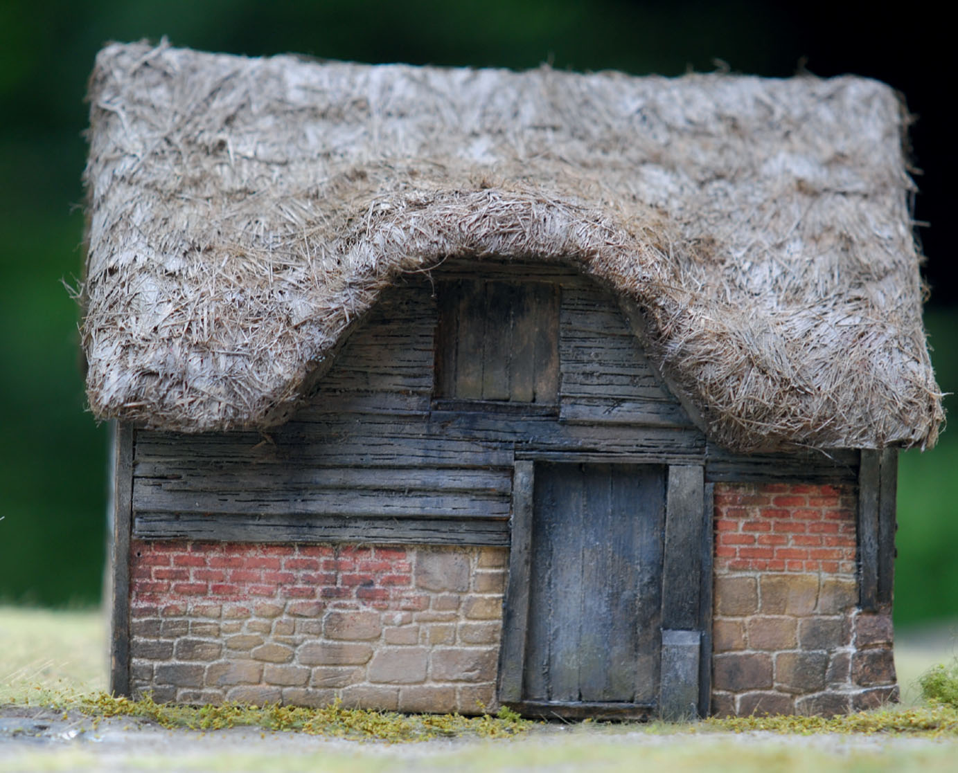
PROJECT 4: CONSTRUCTING A SMALL HAY BARN
This project presents the construction of a small hay barn based on a prototype I found when visiting the small Derbyshire village of Dale Abbey in 2016. The thought of a model came to mind as soon as I saw this rustic barn. While there I took a series of reference photographs, including many close-ups, made an estimate of its dimensions and took some notes. Together this would provide the reference source needed to make a start on a model.
I decided that the model should be made to 1:43 scale (7mm to the foot), which would allow all the textures and details to be faithfully executed. A scale drawing was made from the information obtained at the site, including the photographs. Construction materials for the model were then selected, settling on Corri-Cor board. It helped that a local picture framer had given me a quantity of offcuts.
The elevations were transferred from the drawing and marked out on the card, before being cut out with the scalpel. They were then laid out ready to receive the cladding materials and the mixed masonry. I decided that all the materials could be applied on the flat elevations before concentrating on the assembly. Looking at the photographs I noticed that the barn was built with stone from the footings up to about a third of the total wall height. The stone had been robbed from the demolished remains of the abbey. In fact recycled stones from the abbey can be found in most of the buildings throughout the rest of the village.
To replicate the stone and other masonry I used a thin skin of Das modelling clay, so the base areas of the card were first coated with PVA for the Das to adhere to. To achieve the thin skin required, I kept my fingers wet when applying the clay. The clay was left to dry for the usual twenty-four hours before any scribing was attempted. The stones were all different sizes and were mixed with small areas of brickwork included as infill material. The scribing therefore followed the irregular coursing of this masonry. This is where Das scores over any of the embossed sheets as different types of masonry can be mixed together when scribing them.
With the base masonry all scribed, I decided to add the paint, picking out both the stonework and brickwork, while still working on the flat elevations. This was applied in the same way as described before for the stonework, matching the shades of the sandstone. The brickwork would also follow the same application after a wash of light grey was brushed on to match the mortar colour. A mix was then made up from Warm Red, Chrome Orange, Burnt Sienna, Naples Yellow, Payne’s Grey and Titanium White. Dry brushing shades made from these colours from the tube replicated the rustic finish of the brickwork.

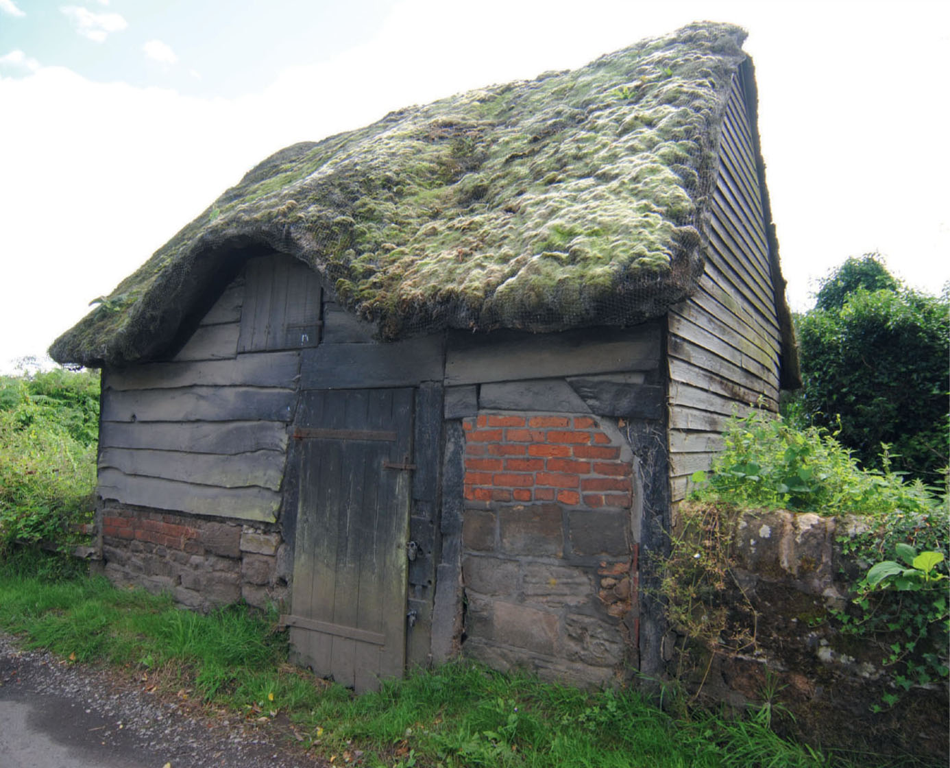
A rustic timber-clad thatched barn in the village of Dale Abbey provided prototypical inspiration for this diorama.
The next decision was what material to use for the lapboard cladding covering the top two-thirds of this building. It was decided to attempt to build the whole barn from recycled and scrap materials, just like the prototype. With this in mind, some wood veneer salvaged from an old wardrobe door was found to have the right rustic texture but was rather thick for the scale of this model. The solution was to split the veneer along the grain after cutting it into the individual planks. With the planks now half the thickness of the original veneer, the scale looked right especially when it came to the overlapping.
The boards could now be glued on overlapping each other, working from the lowest level right up to the roofline. I tried to pre-cut the boards to length first before fitting, although they can be trimmed afterwards by turning over the whole side or end. I was very pleased with the finish the veneer had given and even the natural colour looked good, but the photographs showed that the timber had weathered to show lighter shades of grey. I decided to paint and weather the timber after assembly as it would be easier to apply.
It was now time to look at the main assembly of the walls to the gable ends. Square balsa strips were used to reinforce the corners and I also included some stretcher bracing, using offcuts of the cardboard. With the walls now assembled, more Das was applied to make the corner stones at the base, and vertical timbers were positioned at the corners. Three of the corners would have boards stretching from the ground to the roof, with the fourth board sitting on the stone plinth underneath. Vertical boards of varying widths were fitted as doorposts, all adding to the barn’s rustic appearance.
The next stage was to fit the large door and the two hayloft doors positioned in the centre of the raised dormer on each side of the building. All the doors were made from 1mm card, which was first scored with all the planking, then scratched with a scalpel to create the distressed finish. The doors all required strap hinges, which were fabricated from strips of card for the straps, with short lengths of styrene rod added to create the actual hinge. Before fitting the doors, they were given a coat of Matt Tank Grey from the Humbrol acrylic spray range.
It was now time to fit the two main doors and the two hayloft doors. The adjusted corners would require painting to match the stonework, although extra painting and weathering could be executed at the finishing stage. With the walls now completed, attention could be brought to constructing the thatched roof.
The first task would be to make the supports to hold the roof panels in place. These were simply four lengths of 5 x 5mm balsa wood glued to the inside of the gable end wall. With these fixed into position the roof panels could be first marked and then cut out. The main roof was measured out from the main side and end walls, making allowance for about 3mm for the overhang on the bottom edge and the two side edges. The two panels were then cut out and positioned temporarily to make sure the overhang looked right, and to mark where the dormer started and ended. With this marked the panel was cut away for the roof to form the eyebrow over the dormer.
Before gluing in position, however, it was necessary to consider how to create the depth of the thatch on the main roof. Considering the original plan to use only scrap and recycled materials for this project, a search for something suitable came up with a few polystyrene pizza bases with a depth of about 6mm. This would be ideal and an easy material to work with.
The polystyrene was cut roughly to size before being glued to the panel. Any excess overhanging polystyrene could be cut away by turning the panel over, leaving a neat edge on the sides and front. The top edge, which would join up to form the ridge, would need to be left over for the time being. The area that would form the dormer now had to be cut away. Total accuracy was not essential, but a card template can be used to indicate the outline to be cut.
The roof panels, with the polystyrene glued on, could now be glued in position. The edge of the polystyrene was roughly shaped using a scalpel to cut away the facing edge at an angle of forty-five degrees. The top edge where the roof panels meet at an angle needed to be cut to roughly form the ridge.
The next task was to make up the eyebrows over the two dormers, starting with the sub-bases. Corri-Cor was again used for this, first making up thin card templates before cutting the final panels. Once happy that the sub-base panels fitted up to the main roof correctly, these could be glued into position.
The eyebrow was next covered with polystyrene from the pizza base, which was first cut roughly to shape and glued to the sub-base. As with the main roof, all the edges could be shaped first on the edges. At this stage all the gaps left, including the ridge, were filled in using Das modelling clay, letting this dry in the usual way until any roughness could be sanded away. The edges of the polystyrene can also be sanded at the same time to give a neat, rounded edge.
The base of the roof was now ready to take the thatch, but first the polystyrene base needed painting using acrylic paint, since oil paints would possibly react with the polystyrene. Payne’s Grey and Yellow Ochre were mixed together to form the base colour, which was brushed on all over, not forgetting the sides.
The thatch could now be attempted, selecting the traditional plumber’s hemp as the thatching material. It was decided to attempt to replicate the techniques employed by actual thatchers. This required making small wire staples (or withies) to attach the bundles of the hemp to the roof. This was another good reason for using the polystyrene pizza base, since the staples could easily be pushed into it.
The hemp was first cut to make bundles about 20mm long. Each bundle of hemp was then secured, starting with the first row overhanging the eaves by about 10mm. The successive rows would then overlap the previous row by 10mm. The hemp would also follow the eyebrow profile over the loft dormers. Although the wire staples appeared to be holding the individual clumps in place, there were still doubts that all the hemp was secure. For peace of mind, some watered-down PVA was brushed on to make the connection more secure.
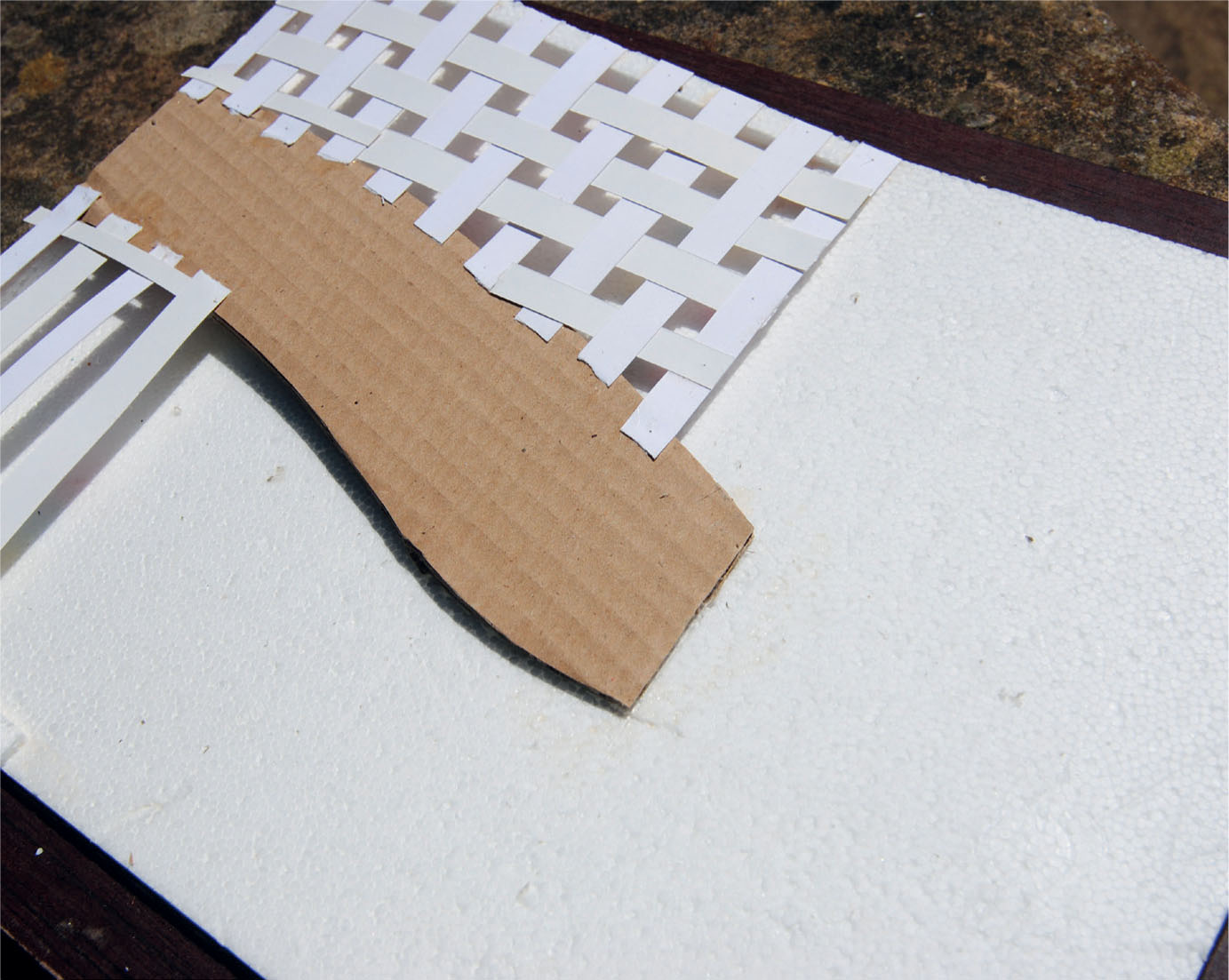
In order to construct the landform for this diorama, polystyrene packaging was used for the lowest level. The higher level of the lane was formed from corrugated cardboard, while card strip supported the higher levels of the landscape.
The lane has here been surfaced using fine sand and a little Das modelling clay to make the rough verges.
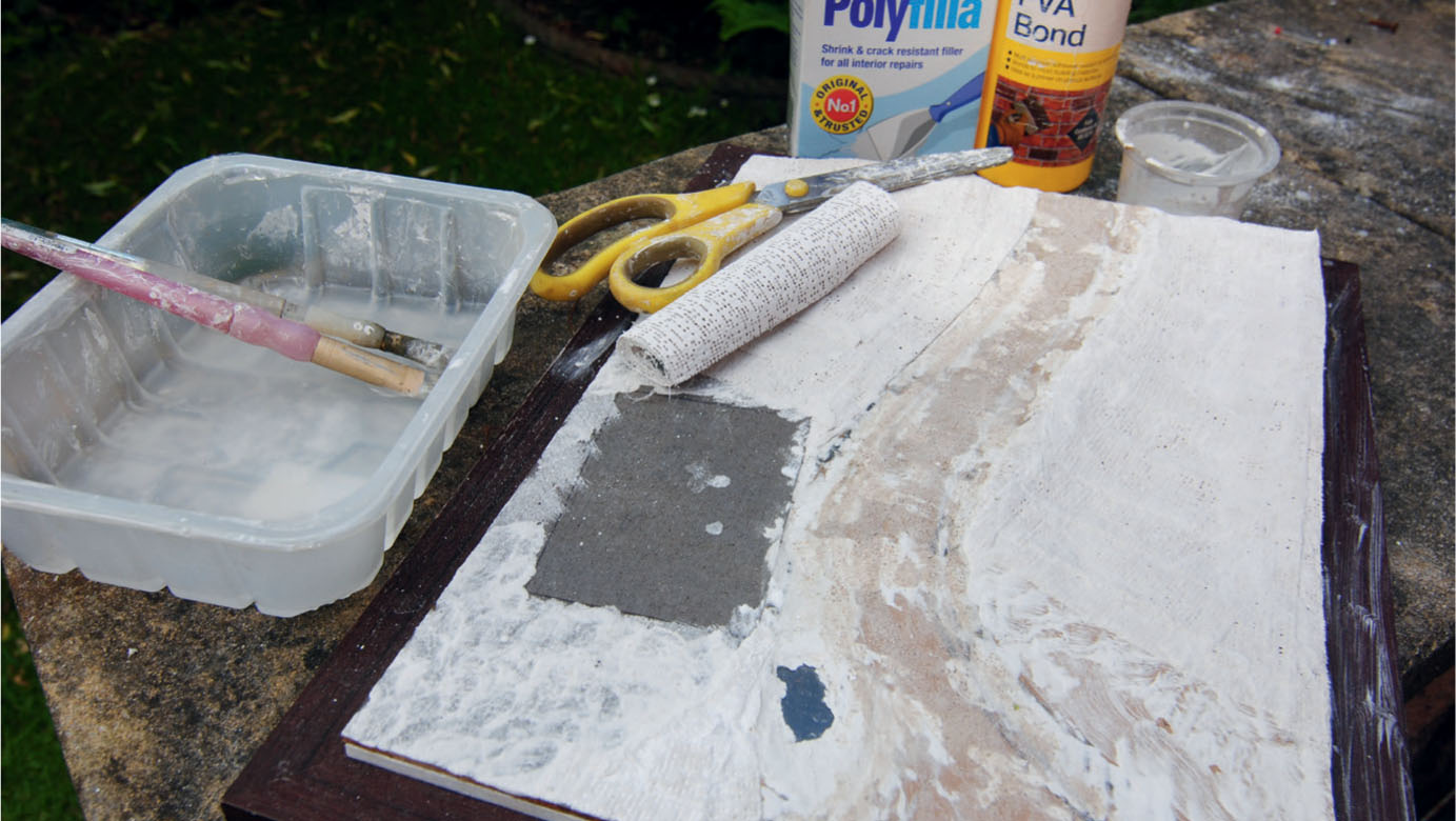
The landform has been built up using the plaster bandage to create a rigid surface. Polyfilla has been applied over the plaster bandage in places to improve the rigidity.

The earth ground colour has been added using a mix of Burnt Umber, Yellow Ochre and Payne’s Grey.
A close-up showing how the paint has been applied to replicate the surface of the lane’s prototype.
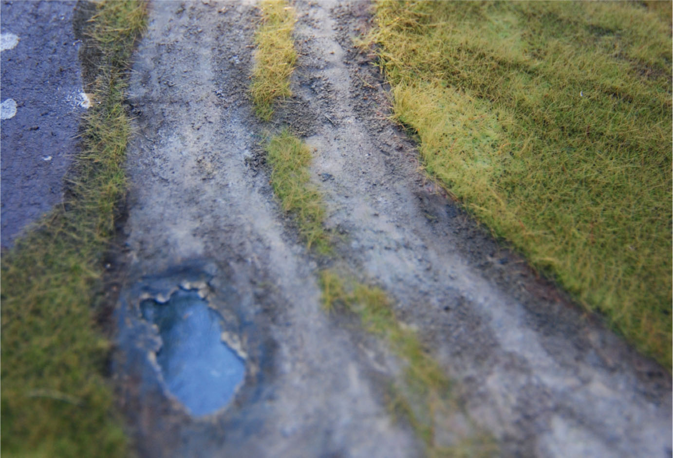
Using the applicator, various lengths of static grass fibres have been added to the fields, verges and the strip in the centre of the lane.

Some of the salvaged material used to construct the barn. The side that has been nearly completed illustrates the use of some of these materials.
Once the PVA had dried, any overhanging hemp could be trimmed off with sharp scissors, starting at the eaves. Further trimming saw the thatch taking shape. The ridge would need trimming carefully, but with patience a neat finish to the thatch was achieved. The thatch would also have to cover any exposed edges, especially on the gable end.
The thatch now covered the whole roof area and would need painting. The thatch on this barn was very well worn and was ready for a rethatch. In order to match a colour to replicate the state of the thatch, the oil paints selected from the tube were Burnt Umber, Payne’s Grey, Yellow Ochre, Naples Yellow and Titanium White. By mixing these colours together on the palette, it was possible to find a shade that matched the reference photographs.
The paint was first thinned down with thinners so that the paint might flow into the fibres of the hemp. This was followed by brushing dryer paint over the thatch, concentrating on the lighter shades and highlighting the thatch in various places. Always keep looking at reference photographs of the prototype and try to match what you see. Due to its dilapidated state the thatch would require plenty of weathering, especially to replicate the moss growing over one side of the roof. For this a very fine green foam flock from one of the scenic suppliers was used. Dabs of PVA were placed on the thatch with a brush, closely following the photographs to see where the moss appeared. The flock was then scattered over the roof. The particles that became attached to the dabs of glue were left a while to bond, before shaking the rest of the flock away to use again.
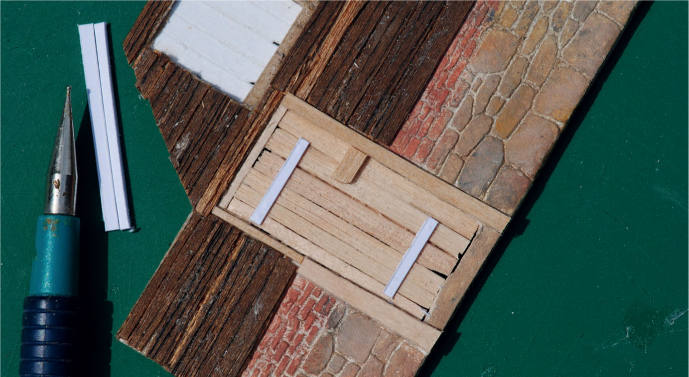
This close-up of the side shows how scrap veneer has been used for the lap boarding and coffee stirrers for the planked door. The lower level masonry has been scribed into an added skin of Das modelling clay.
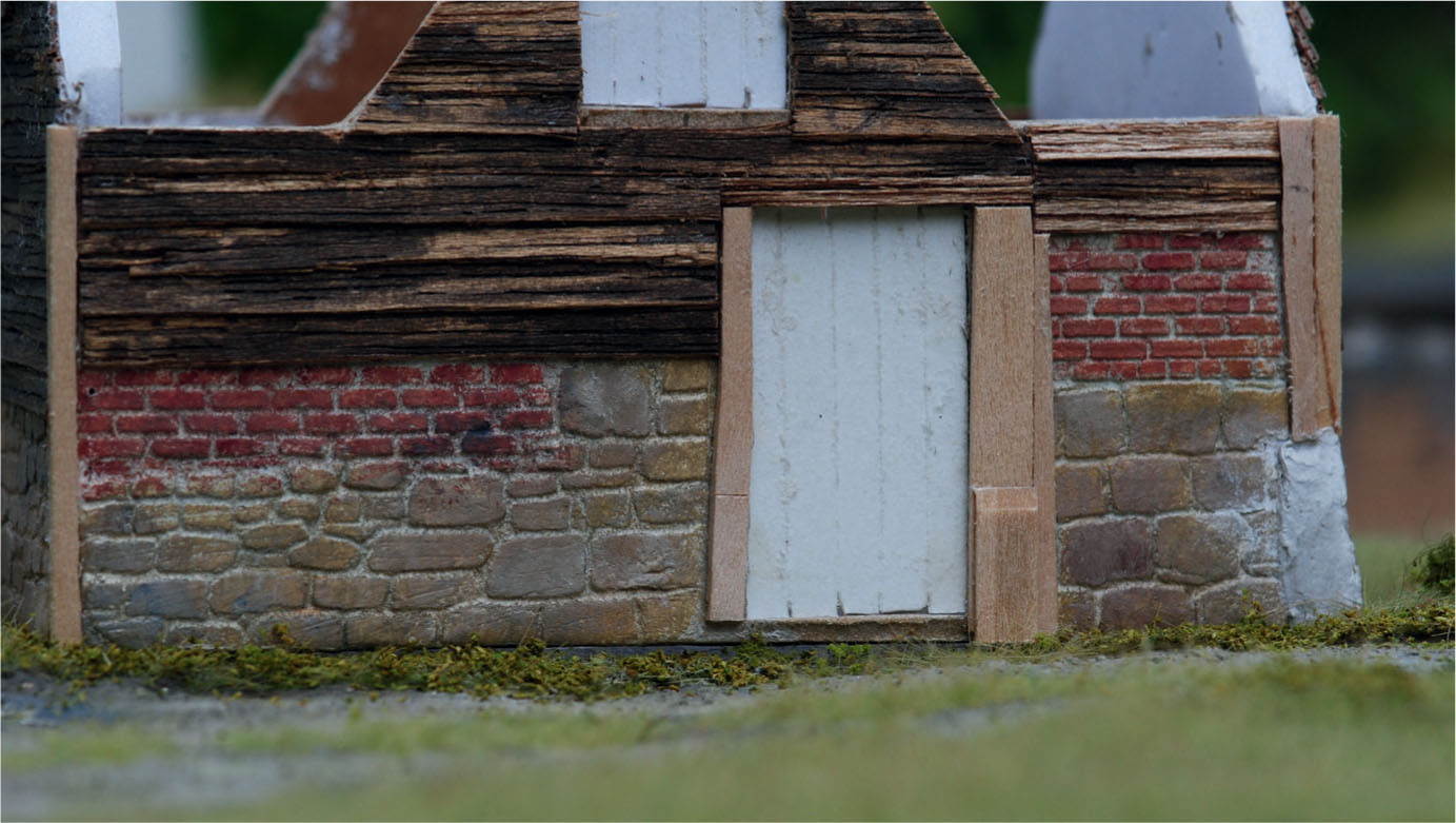
Assembly has started and timber strips have been added on the corners and doorposts. The door on this side has been made from card, using a scalpel to score and distress all the planks.
Coats of pitch were used to help preserve the doors of the prototype. This effect is replicated by painting with a nearly dry brush.
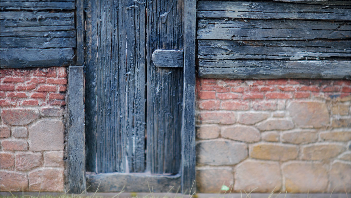
The door on the other side has also been weathered using dry brushed paint.
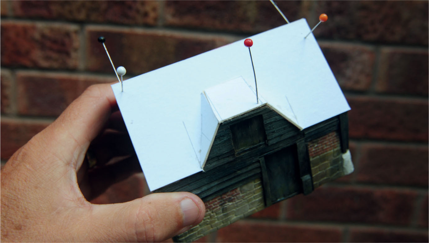
The sub-base of the roof, made from picture mounting board, has here been glued into position and pinned.

The polystyrene has been cut and glued to the sub-base. Pins have been used to secure the polystyrene until the PVA glue has bonded.

The polystyrene has been shaped on all the facing edges to create the basic shape of the thatch.
The model barn was now complete, ready to be planted in the space waiting on the diorama. Most of the techniques used for this diorama were the same as those described earlier for the country lane project, except for the use of a sheet of polystyrene packaging instead of the insulation foam. This diorama also featured a country lane running through the centre. The hay barn was positioned right alongside the lane on the model, just as it was found in the real location.
The diorama could now be dressed to complete the rural scene, with a gypsy caravan parked opposite the barn, a horse tethered to a post and the family sitting around the camp fire. This little cameo seemed well suited to this rustic setting, depicting country life in days gone by.

The shaped polystyrene can here be seen around the dormer. Any gaps that show can be filled using small amounts of Das modelling clay.
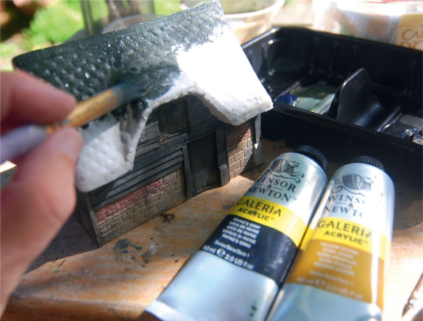
The polystyrene base is painted using an acrylic mix of Payne’s Grey with Yellow Ochre. Acrylic paint has been chosen here since oil paint might dissolve the polystyrene.
The material used to create the actual thatch. Plumber’s hemp always gives a realistic result. Staples were used to attach the bundles of hemp to the polystyrene base.
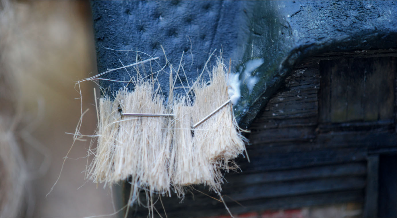
The first stages of adding the bundles of hemp to the roof, starting in a corner and at the eaves. Here a staple was used as well as a dab of PVA glue.

The hemp has here been attached to the whole base of the roof, making sure the bundles overlap each other.
The thatch has been finished by lightly trimming with sharp scissors until a realistic result is achieved.
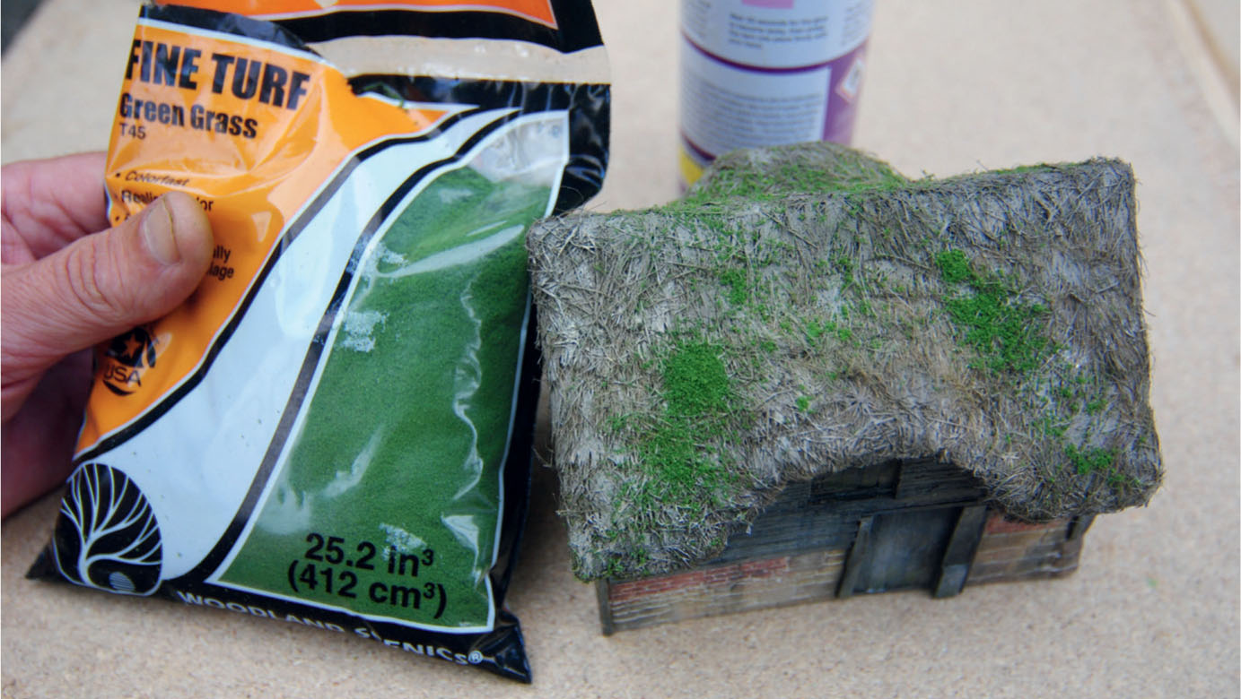
The thatch has been painted using the same colours as the base, although choosing oil paint this time and thinning it down to a wash. A very fine green flock has been used to replicate the growth of moss, which was very evident on the wellworn prototype.

The prototype shows many signs of weathering, including the moss growing on the thatch.
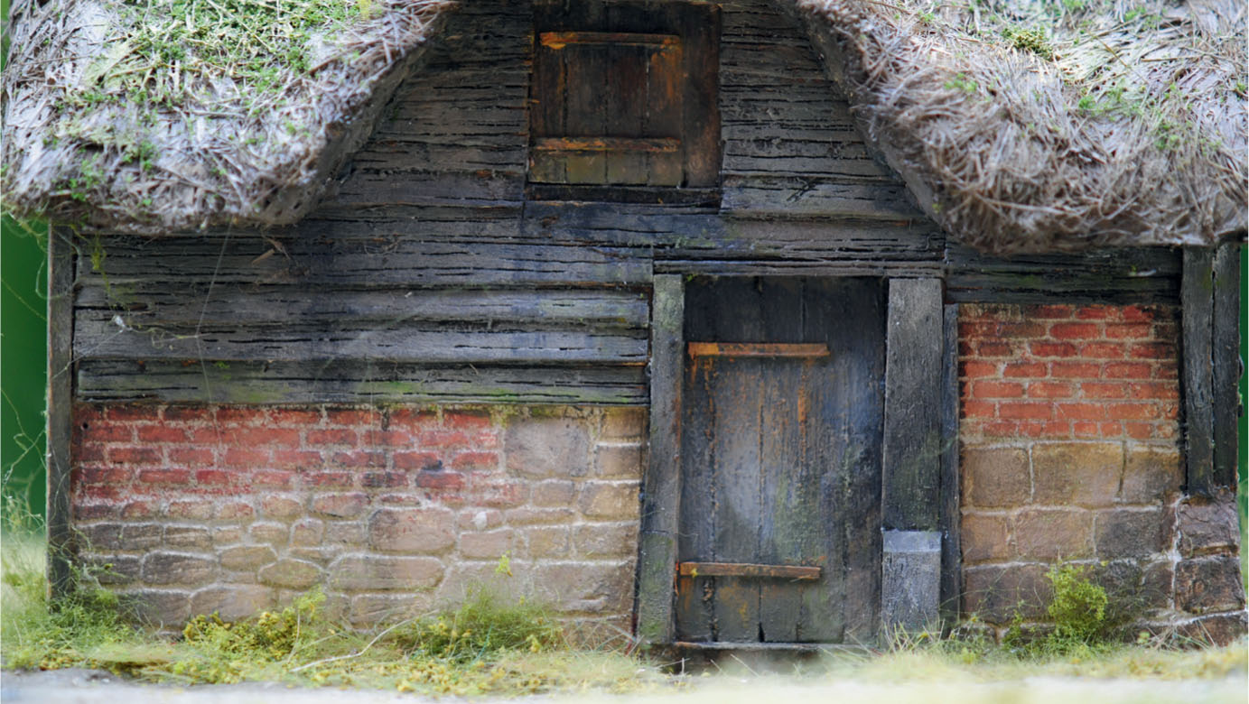
This close-up view shows how the overall weathering has been replicated on the model, including the rust on the barn door hinges.
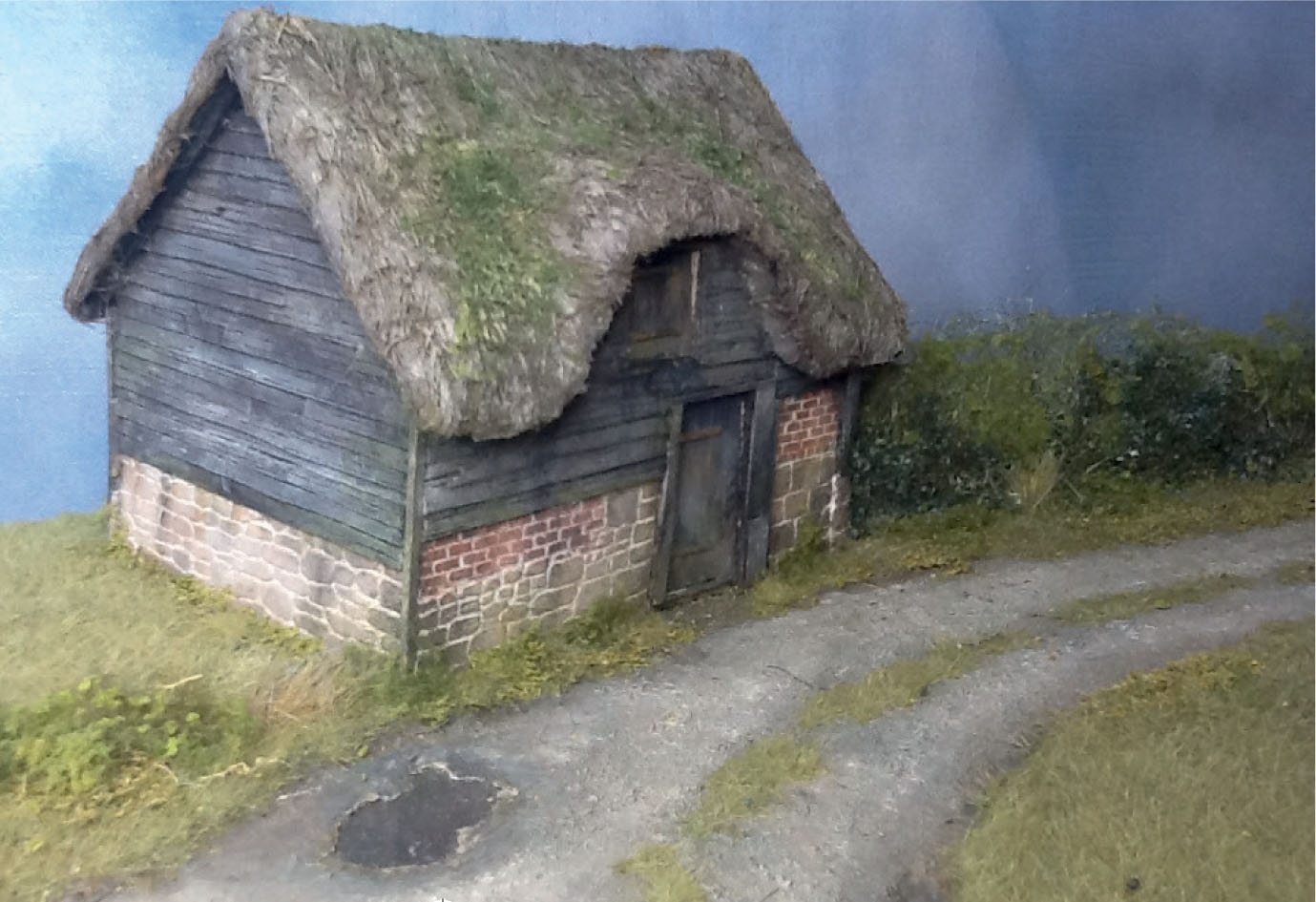
The barn seen in its final position on the scenic diorama. The modelled hedge helps the building to blend with its scenic surroundings.
The gypsy caravan has been brought in to create a finishing touch to this view of the barn in its rural setting.
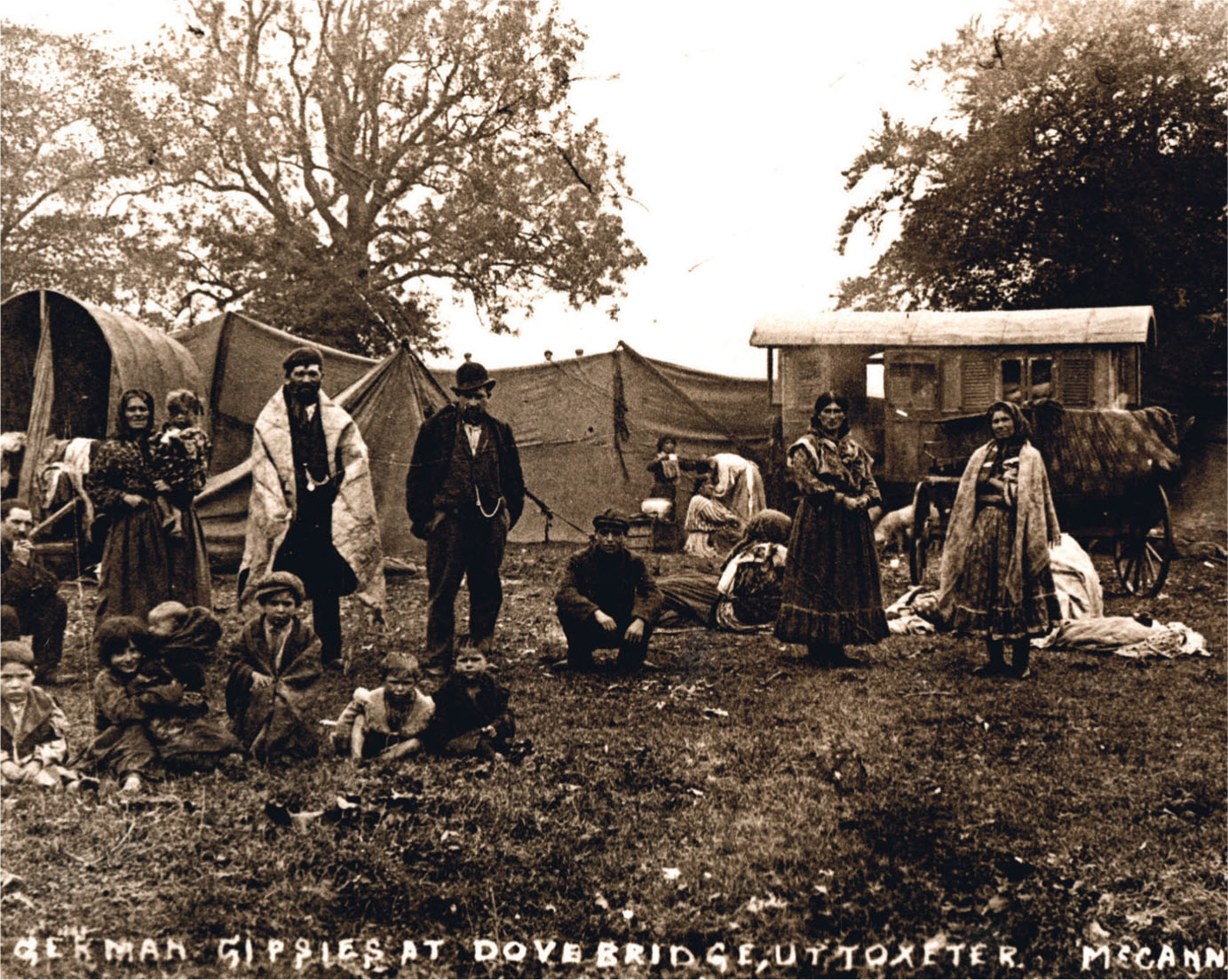
The idea for adding the caravan to the diorama came from this photograph. It is scenes of rural life like this that inspire us to recapture the spirit of days gone by in miniature form.
PROJECT 5: MAKING A SCENIC WATERFALL
To complete the water-based modelling projects in this chapter, I have included a totally scenic diorama featuring a waterfall. A feature like this will appear on any fast-flowing river or stream where the contours and the local geology force a watercourse to drop from a higher level to a lower one. This drop can range from less than a foot through to many feet. In other cases the total drop may be spread over a distance that includes a series of waterfalls.
A waterfall is always an interesting addition to the representation of a river or stream on a model railway or scenic diorama. This is why I have chosen to include a high waterfall breaking over a rocky crag and falling into a large pool below. When choosing this project, like any other, the first stage would be to obtain reference. This prompted visits to a number of waterfalls, including the Light Spout waterfall high on the Long Mynd in Shropshire, which provided the inspiration for this project.
MAKING A START
The starting point for this model would again be the baseboard on which the diorama would be constructed. A piece of Daler Board was selected and cut to size, measuring 10 x 10in (240 x 240mm). The surface of this board would form the bed of the pool at the bottom of the waterfall, the very lowest level of the model. The pool area was then marked out on the board, keeping it within the nearest corner to the viewer. This would concentrate the line of the stream running diagonally from the far rear corner to the front corner.
The next task was to determine the height of the stream flowing above the waterfall. Once this had been decided, Corri-Cor was used to make a cardboard box that was just under the total height required. The box was then brought into position at an angle of forty-five degrees. Another piece of cardboard was positioned so that it was overhanging the front of the box by about 1in (25mm). This would form the lip for the waterfall and the surface would create the bed of the stream at this upper level. The rear of this piece of card was left oversize so it could be cut after the next stage. Two extra pieces of card were laid on top of one another, stepped back from the front and cut at different angles. These would form a couple of small falls as the stream approached the large fall, requiring the facing edge to be cut at an angle of around forty-five degrees.

Prototype inspiration found at Lumsdale Valley, Derbyshire.

This group of waterfalls inspired the modelling project and provided reference material.

The Light Spout waterfall on the Long Mynd in Shropshire was the main inspiration for this model diorama.
FORMING THE MAIN WATERFALL
The box was glued to the baseboard, with the card hanging over the front. The next task was to build up the rock crag over which the water would fall.
Pieces of tree bark were found to resemble the rock crag perfectly. These were glued into position right up to the front of the box, leaving the top piece of card overhanging the top of the bark. This could now be cut to follow the shape of the face of the bark, using a very sharp blade in the scalpel cutting at an angle rather than straight. It goes without saying that extreme care must be taken when using sharp blades to make these cuts.
The next stage would be to add further pieces of the bark at the top of the main fall and some at the bottom; these however, would be positioned and glued in horizontally rather than used vertically when forming the face of the crag.
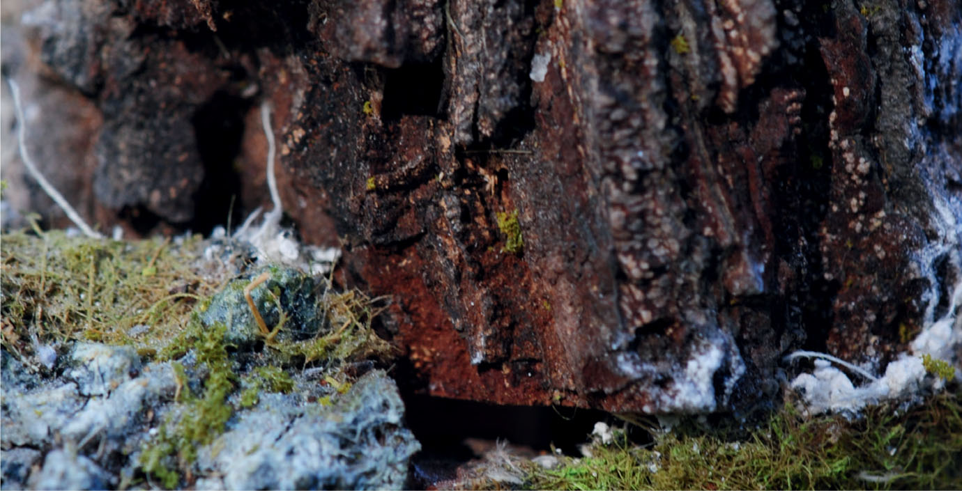
Tree bark was the chosen material to produce the crag and rock faces.

The crag and rock faces are here in position, together with the profile boards to form the land’s contours. Some of the lower scenery has already been completed.
Strips of card have been glued to the profile boards and attached to the lower landforms. These will provide support for the higher landform and around the crag.

The card strip supports are covered with plaster bandage and extra coats of Polyfilla are brushed on to fill any gaps around the crags.

The landform has now been painted and clumps of carpet underlay felt have been glued on to form the rough scrubland around the crag.
Smaller rocks were then glued in again, both at the top and bordering the pool at the bottom. Small stones collected on walks in the Peak District were used along with grey cat litter to create the smallest rocks positioned within the stream and the lower pool.
FORMING THE SURROUNDING LANDSCAPE
Moving on to the landscape, the first job was to make up the three profile boards, two for the sides and one for the back. Good-quality rigid corrugated cardboard was used and the three pieces were offered up into position to mark the contour profiles required. Once these had been cut to the top edge, they could fixed and glued into position with the aid of balsa wood supports fixed on the inside.
Additional small balsa supports were glued to follow the profile needed to support the card matrix. This would again be made by cutting strips of card from recycled packaging. Before these were fixed into position, some extra support was provided by inserting plenty of screwed-up newspaper to help support any material put on top. Now the strips were glued from the profile boards to the base first, followed with strips placed in the opposite direction, securing them again from the profile boards to either the tree bark or the face of the card forming the upper part of the stream. To secure the strips while the glue bonds, I would recommend pinning them in place with dressmaker’s pins. When constructing the matrix of card and weaving it together, PVA will be needed to secure the joins. As this will take a while to bond, place a paper clip over each join until the bond is made.
The land can be formed once the foundation support is complete and all the bonding has dried successfully. Torn strips of newspaper were soaked in PVA and then placed over the matrix framework. Extra PVA was next brushed over the positioned strips of newspaper to create a practical base for the scenery. This was then left for a while to set so that it would be ready for the next stage.
The newspaper would only create the sub-base for the scenery as a second skin would be added over the top to make a more substantial landform. For this Gaugemaster Mod Roc plaster bandage was selected. The best way to apply this material is to first cut it into manageable strips. The first strip should be immersed in a tray of water before being positioned over the top of the newspaper sub-base. Repeat as necessary, applying all the strips in the same direction. Once all the area has been covered, further strips can be applied in the opposite direction, until there is a double thickness skin all over. Extra plaster can be applied with a brush, mixing up some Polyfilla and brushing it over the main land formation, making sure to brush plaster into all the nooks and crannies around the rock faces.
Once all the plaster had completely dried, a solid skin was now ready for painting. A ground colour was made from mixing Payne’s Grey, Burnt Umber and Yellow Ochre together in a tin. This was brushed on with a large filbert brush, using a smaller brush to apply the paint into any awkward corners. The same mix of paint can also be applied to the bed of the stream and to the pool, making sure to avoid painting over any of the rocks.
The landscape was now ready for the grass and other scrub vegetation to be added. Static grass was added first into a bed of PVA, using the static grass applicator. This was followed with selected clumps of teddy bear fur and a number of scenic flocks and scatters. This model diorama would benefit from a small tree, but in such an exposed location the tree would be windswept.
CREATING THE WATERFALL
It was now time to model the main feature of this scenic model, the waterfall. Just as I have previously experimented with Making Waves from Deluxe Materials, here I have decided to try out Scenic Fibres from the same supplier. The fine nylon fibres were first cut, before being teased away from the bundle. Small amounts of the fibres were laid out, trying to keep them straight, and secured with PVA to the forward edge of the stream and to the top of the bark forming the rocky crag.
More lengths of the fibre were attached in the same way. When the glue had bonded, the fibres were gently combed in the direction of the falling water. This operation needs perseverance as it may take some time until it looks right. Extra fibres were now added around halfway down to where the water ran off the side of the crag. All the time I was positioning and gluing the fibres, I was referring to photographs of waterfalls.

The waterfall is now in place. Scenic Fibres, a soft nylon material produced by Deluxe Materials, has to be combed in the direction of the falling water.

An artists’ fixative spray is the first stage in creating the look of water. This also makes the fibres more solid.

The fibres are then painted with white oil paint and gloss varnish. White water is also added to the base of the falls and at the top where the flow is concentrated through the rocks.
Once all the fibres were in place and the visual appearance seemed correct, it was necessary to make the actual fibres look more like falling water. For this, the fibres were first sprayed with artist’s gloss fixative spray before painting on a mixture of white oil paint together with gloss clear picture varnish. This combination gave the required result, making for a convincing representation of real falling water.
Water would now need to be added to both the stream above the waterfall and the pool at the bottom. Gloss clear picture varnish was again used, brushing on a few coats and taking the varnish over the fibre at the top of the falls. The varnish was also carefully brushed on around all the exposed rocks. The white water was then added using thinned-down Titanium White oil paint, adding this to follow the flow of the water from the stream at the top through to the pool at the bottom. When adding the white water, always refer to photographs of the real thing.
In order to provide the finishing touches, I noticed that a build-up of green algae on the rocks and the crag of Light Spout waterfall was especially evident behind and next to the falling water. This type of growth would be inevitable as these areas are constantly damp. To reproduce the effect, some mid-green oil paint, mainly Sap Green, was mixed and applied to the suspected areas. Before the paint had completely dried, I went over it with gloss clear varnish to replicate the slimy wet finish. Besides the algae growing on the rocks, photographs showed lichens were growing in many areas. These were replicated in the usual way by stippling nearly dry paint onto the rocks.
This was the first time I had attempted to model a large waterfall and I was extremely pleased with the results using these materials. A waterfall such as this will make an interesting scenic feature for any modeller wishing to create a rural landscape.