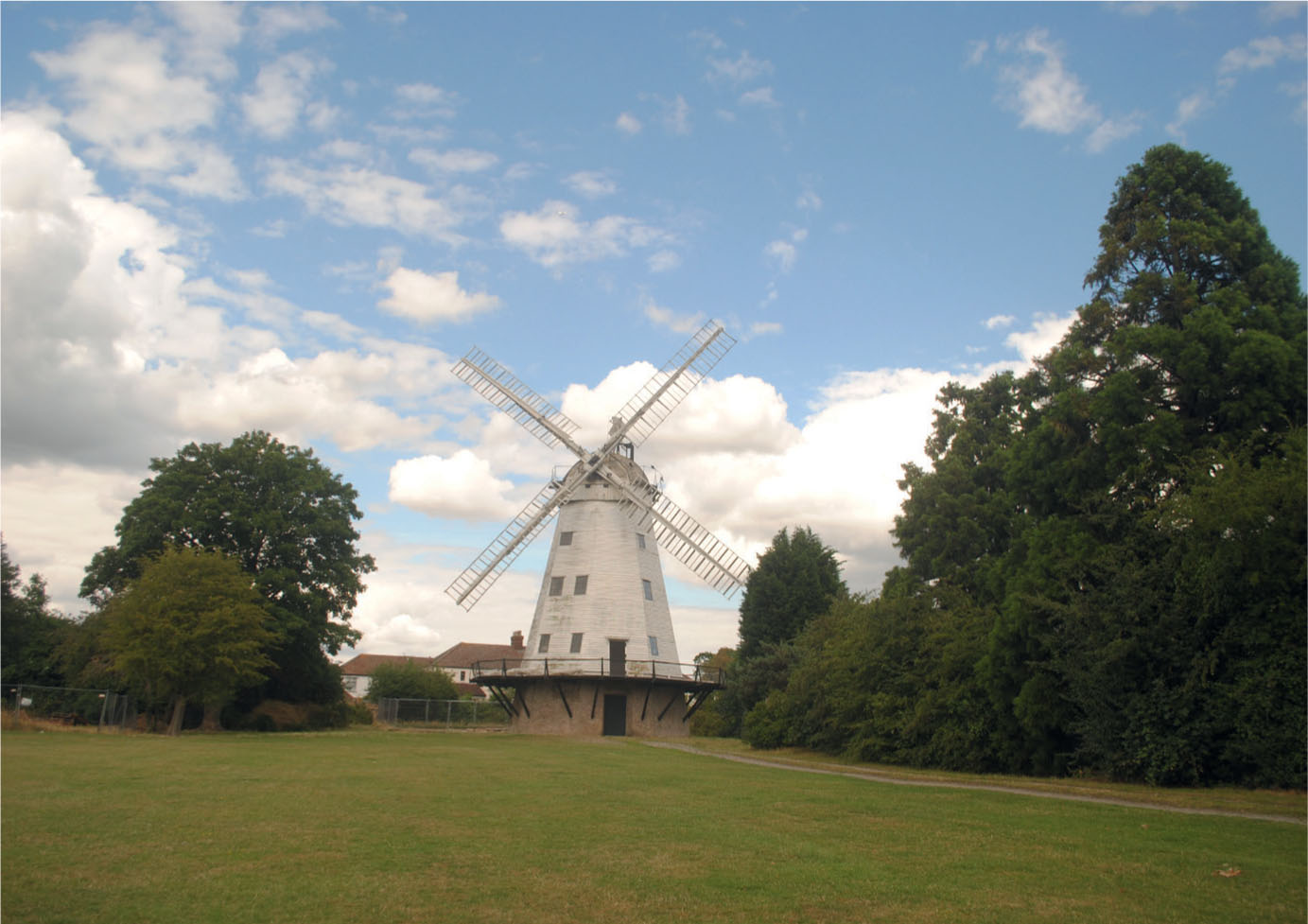
This fine example of a weatherboarded smock windmill is preserved at Upminster in Essex. KAREN WRIGHT
RURAL INDUSTRIES
Further outside the village you are likely to come across some of the industries associated with mills and milling. The miller works directly with farmers to grind the harvested cereal grains into flour or animal feed. The heavy grindstones between which this process is carried out are usually driven by wind or water power. With the crops grown in the vicinity, and the natural power sources readily available, milling became an important industry and feature of the rural scene.
THE WINDMILL
The need to exploit natural, self-renewing power sources has been around for many years. The problem with wind, which is otherwise an infinitely renewable power source, is that it was difficult to exploit when there was either no wind at all or the wind was just too strong. The latter circumstance can be very destructive and windmills can be easily damaged by strong or gale force winds. Windmills were purposely located in remote areas of flat land or on hillsides to take advantage of prevailing winds.
Windmills were first introduced into Britain around the fourteenth century, when advances in technology made it possible to construct powerful and reliable mills. Different designs were built depending on the area and the circumstances needed to harness the available wind.
The earliest form of windmill was the post mill, in which the whole top part of the mill’s superstructure can be turned into the wind. A later development that came to rival this was the tower mill, which features a tall conical tower with a cap that carries the sails and can be turned into the wind by rotating it on a rail positioned at the top of the tower.
This fine example of a weatherboarded smock windmill is preserved at Upminster in Essex. KAREN WRIGHT
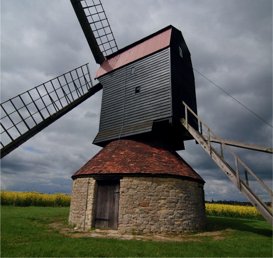
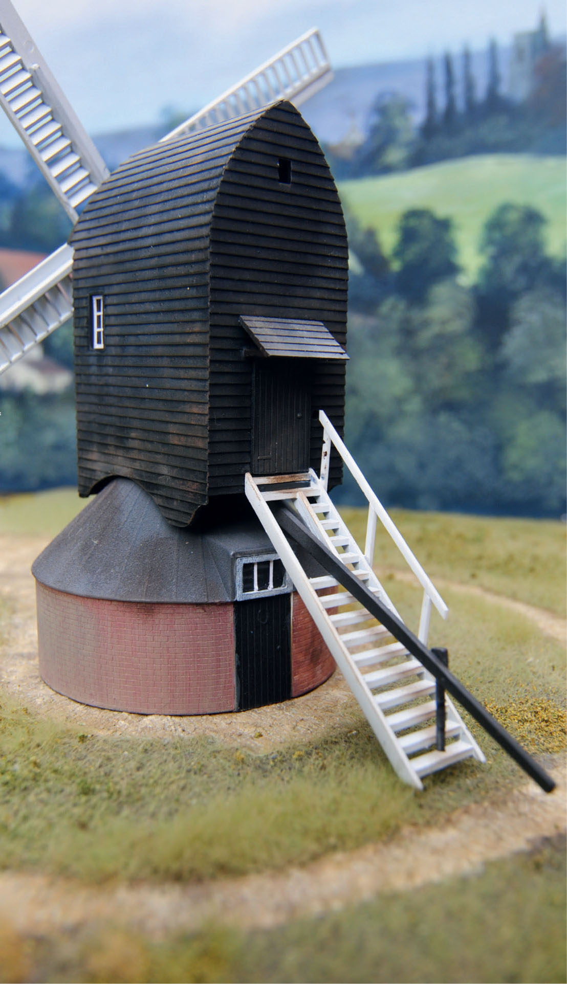
This preserved post mill consists of a timber-clad superstructure rotating on a stone roundhouse base. Note the steps up to the rear and the tail pole used to turn the mill into the wind.
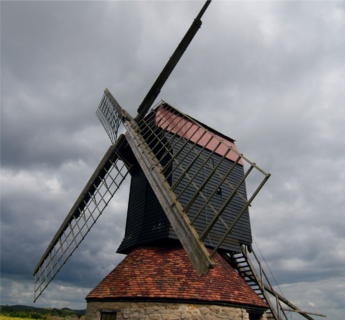
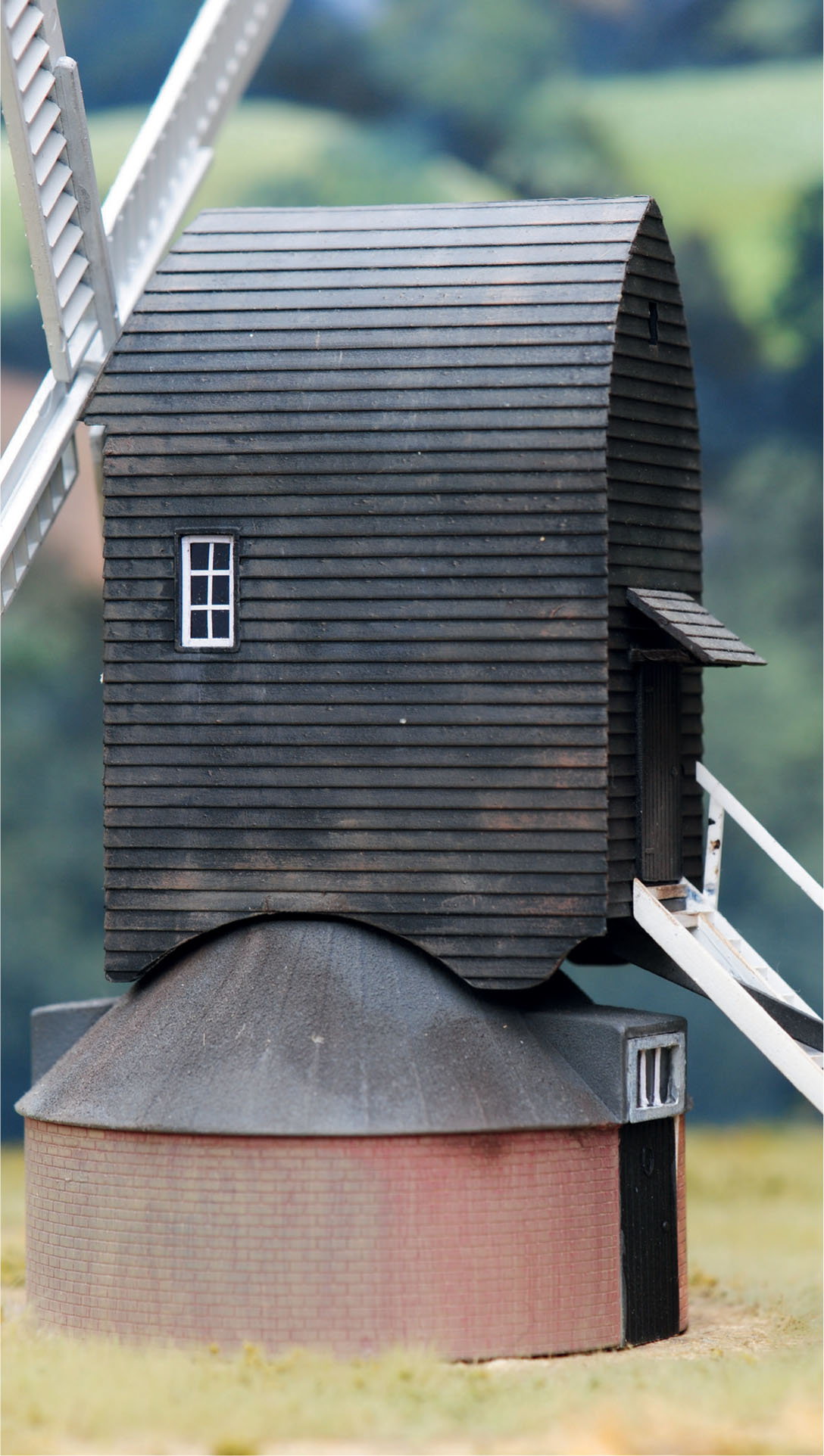
This view of the post mill from the front shows the construction of the sails.
The common factor that links the windmill designs is their reliance on a set of sails. The very early windmills would have sails with simple cloths attached to wooden frames. The sail area could be varied manually by the miller to control the amount of wind required for the task. The miller would also need a reliable brake to stop the sails from turning. Later sails featured shutters, again giving the miller more control of the wind used to grind the corn.
For maximum power to be extracted from the available wind, it was necessary for the axis of the sails to point into the wind. The earlier post mills had a tail pole that allowed the miller to push the body of the mill around until it pointed into the wind. The wind direction was often indicated by a vane fitted high up at the rear of the mill.
The later tower mills had a fantail, a mechanical device that enabled the cap to be turned automatically into the wind. In effect this was a small windmill with eight blades mounted within a frame on the rear of the cap. The fantail turns when the wind strikes it obliquely, driving the cap around on a low geared rack and pinion mechanism.
The other main feature common to mills would be the millstones used in matching pairs for grinding the grains into flour or animal feed. Two stones are mounted horizontally. The upper stone, known as the runner stone, rotates over the bed stone, which remains in a fixed position. Millstones are cut from a substantial single piece of grit stone. The stones are dressed with grooves that allow the milled flour to flow from the stones for collection in sacks.
This is a very basic description of the types and workings of windmills. Further information is available from numerous sources or by visiting one of the preserved working windmills scattered around the country. If you would like to build a model of one of these interesting structures that were so important to the rural economy, I would recommend learning more about the workings of windmills.
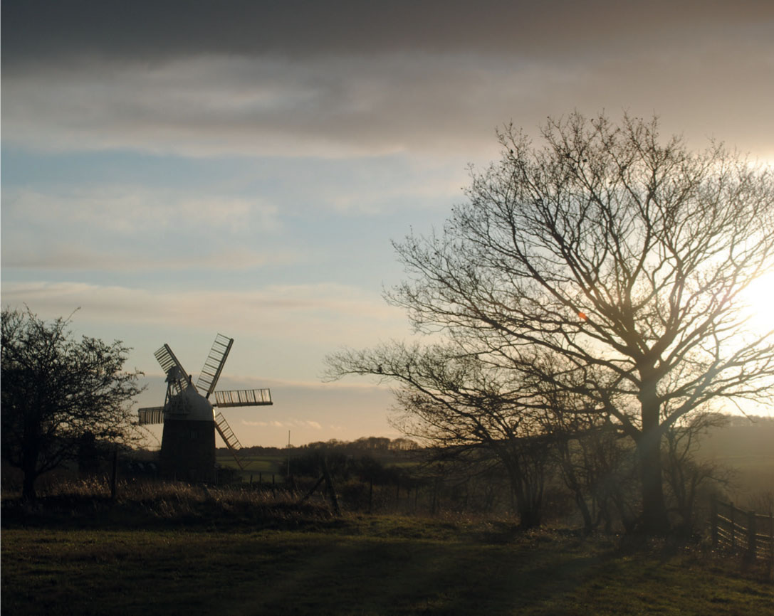
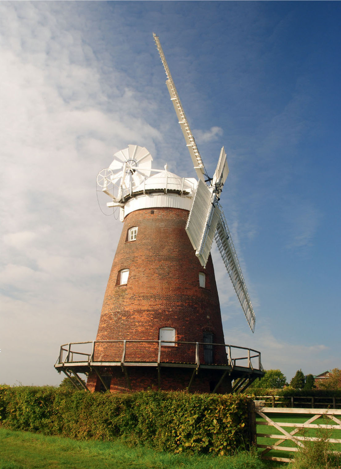
The squat tower mill at Heage in Derbyshire is located on the edge of a hill.
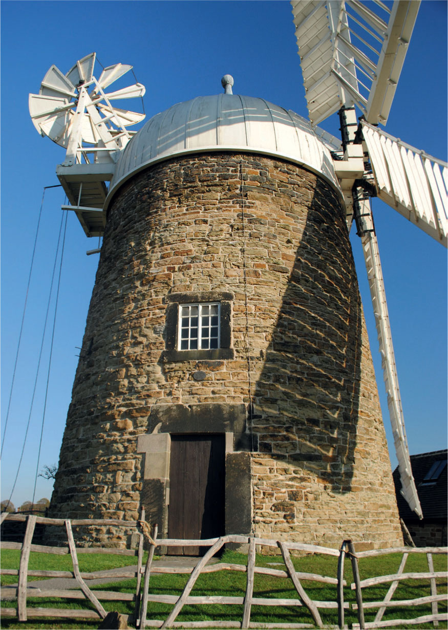
Close-up view of the mill at Heage, showing the rubble stone construction of the tower, together with the cap and fantail fixed to it.
MODELLING A WINDMILL
A windmill will always make an interesting feature to add to a model railway or when simply building a diorama around the mill itself. One of the most popular of the kits and ready to plant models of windmills on the market is a timber-clad post mill originally produced by Airfix and now available from Dapol. The kit has been around for some time, but it’s a very good model that gives a fair representation of this type of windmill.
In keeping with the interest in using scrap and recycled materials I described in Chapter 3, however, I instead propose taking up the challenge to scratch-build a tower windmill based on a card coffee cup. The cup’s profile resembles that of some of the smaller tower mills and its diameter makes it ideal for modelling in 4mm scale.
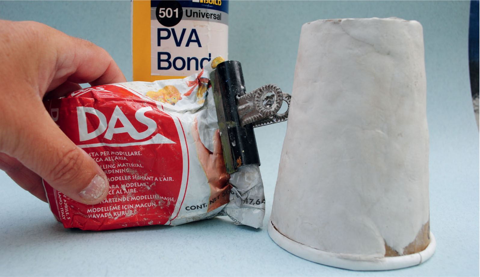
To transform a simple card coffee cup into a stone tower windmill, such as the one at Heage, Das modelling clay is first applied.
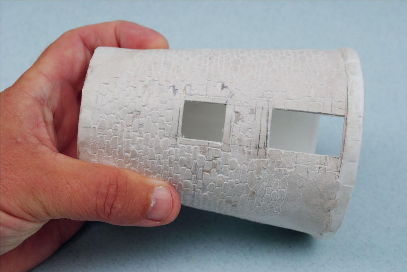
Apertures for the windows and doors are then cut out and the clay is scribed to produce the masonry.
An excellent example of a tower mill, now restored to full working order, is situated on a hillside at Heage, Derbyshire. As a result of this position it required only a small tower and its construction from local sandstone strongly suggested using a skin of Das modelling clay. I was surprised to find that the clay went onto the card cup with ease after applying a couple of coats of PVA.
Even with the reasonably thin skin that could be applied, once the clay was completely dry the cup was quite rigid. Before attempting to scribe the masonry, the windows and the door at the base of the mill were easily cut out using a sharp scalpel. The scribing started with the lintels, sills and upright stones around the windows. The rest of the stonework was then scribed following the rubble stone construction of the prototype.
I have not yet taken this model any further, although I have experimented with painting of stone to see what the results might be. One day I will finish the model just to see if it can be completed using mainly recycled materials.
This kit of a timber-clad post mill was originally made by Airfix and is now available from Dapol.
The Dapol post mill is a very good kit, but here the widows have been fabricated from card and the cladding has been weathered.
Water is a reliable and controllable power source that has been exploited throughout Britain over the years, especially about three hundred years ago. The drawback, however, is that water power is dependent on rainfall. Too much rain can lead to conditions that damage the premises and machinery, putting the mill out of action and destroying the stock.
Watermills were usually constructed of local materials and reflect the prosperity of the area. On tidal rivers mills were built to store and use the energy created by the rise and fall of the tide. Most mills, however, were built alongside a flowing river, from which water would be diverted to a holding pond situated above the mill. When required, a sluice gate was opened to allow the water through, forcing the waterwheel around and powering the machinery inside the mill. The water expelled from the wheel was then taken back to the river, passing through another pond or tail race. The overshot or breast shot wheels installed in most mills meant that a change of level was required for the water to drive the wheel. The main river therefore also needed a drop in level and a weir was built to accommodate this.
Early waterwheels were largely made from wood and were constructed by local craftsmen. Unfortunately wooden wheels had a limited service life due to wear and tear, especially timber rot. From the eighteenth century it became possible to replace them with cast iron counterparts, and it is wheels of this type that have survived. Most wheels were located outside the building, although it was not uncommon for the wheel to be installed inside the building. Outside wheels were commonly supplied with a roof or some other type of cover to help protect the wheel against icing up in the winter.

The old corn mill at Tutbury was converted into a tannery in 1913. Note the arches below the mill where the tail race enters the millpond. The wheel was installed inside the building.
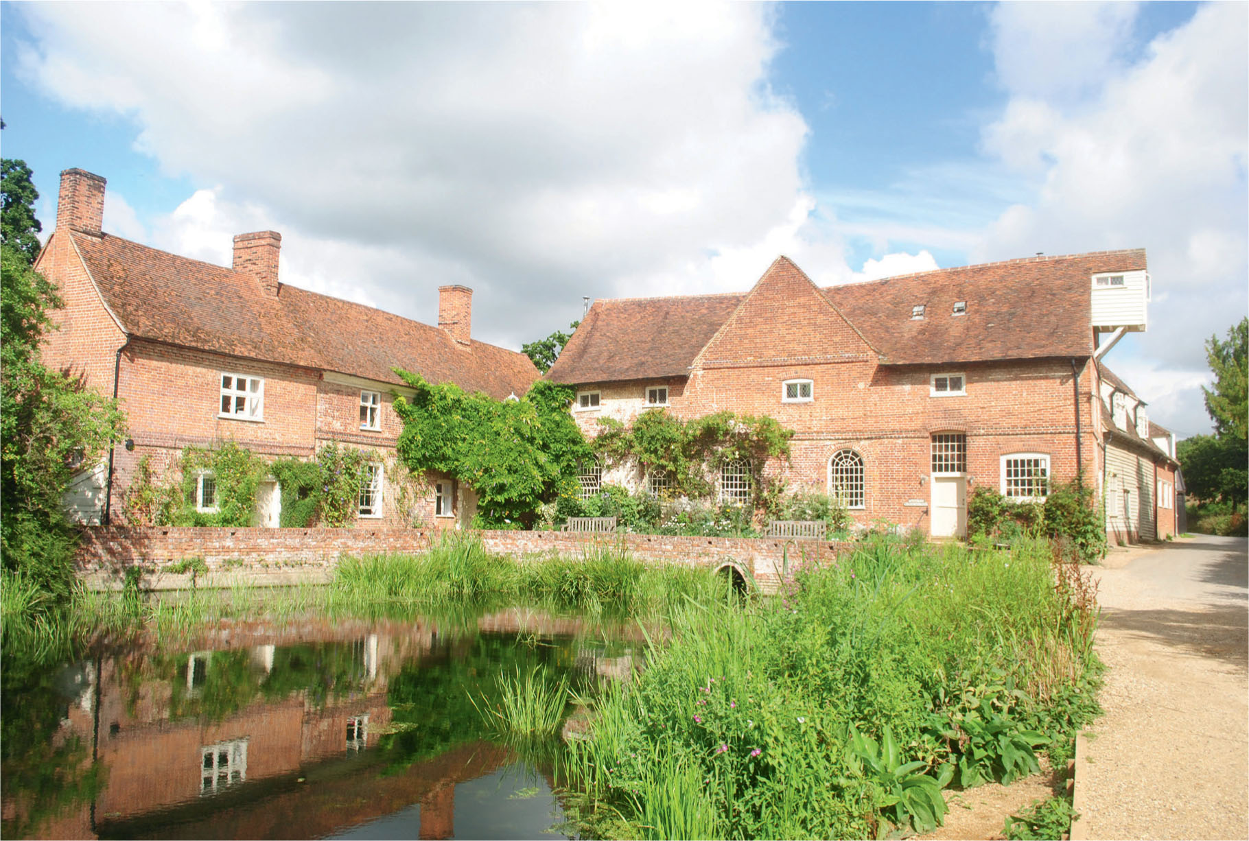
The famous watermill at Flatford in Suffolk.
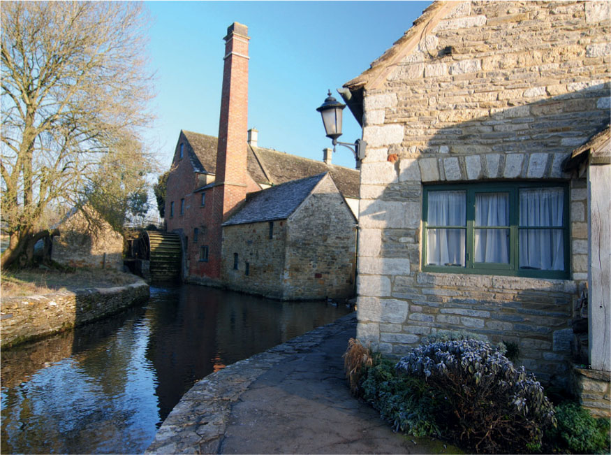
The breastshot watermill at Lower Slaughter, Gloucestershire.
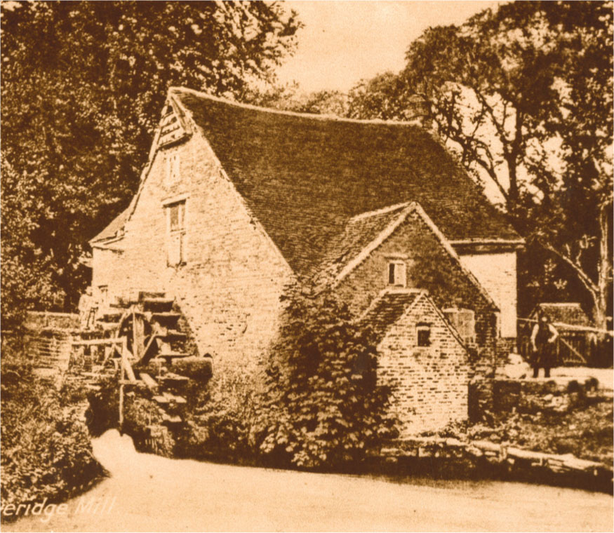
The old breastshot watermill at Doveridge in Derbyshire was demolished in the 1970s. The recesses on the apex of the gable end formed a dovecote.
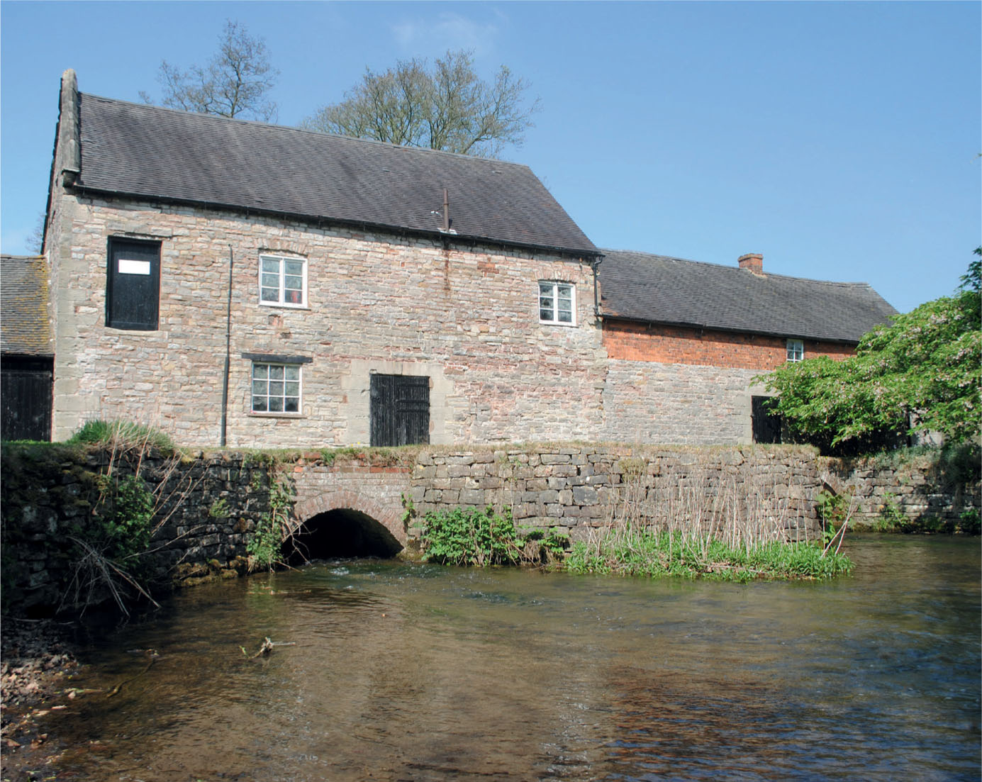
The limestonebuilt watermill at Mayfield on the Derbyshire/Staffordshire border. Note how the sluice exit into the millpond is through the arch, as the waterwheel is integral to the building.
The first watermill to be described below belongs to the river diorama presented in Chapter 3. This mill is situated beside the river and takes its water from a higher level upstream, so a weir is required. The higher levels were constructed on the river early on when making the model, while the weir was put in at the later finishing stages.
This model was based on Melin Bompren corn mill, now reconstructed at St Fagans National Museum of History, near Cardiff. The model, however, has only a single storey and the wheel is located to the side of the building rather than at an end. The roofline follows the prototype and consists of a slated mansard roof.
The components to make up the model were cut from foamboard and artist’s mount board. Next all the window and door apertures were cut out before assembly. For this model etched brass twelve-pane sash window frames were chosen, selected from the range produced by GT Models and available from Freestone Model Accessories. The frames were measured and the apertures cut for them to drop into. The window frames had a bow to the top and this required cutting with a compass cutter matching the curved tops.
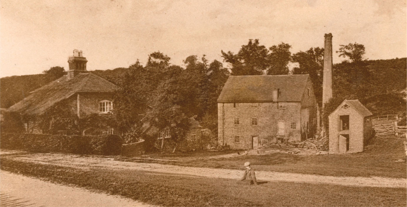
An archive photograph of the mill at Bretby, South Derbyshire. The boiler house and chimney, which has since been demolished, indicate that the mill had been converted to steam power for use when water levels were low.
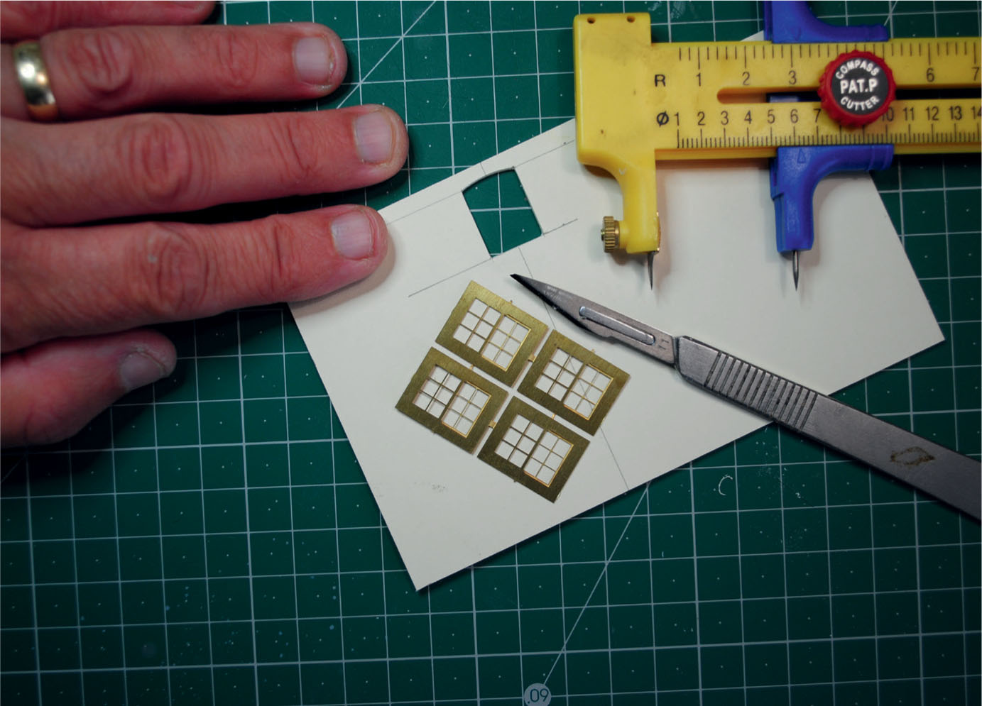
Etched brass sash window frames have been selected for the model of the watermill.
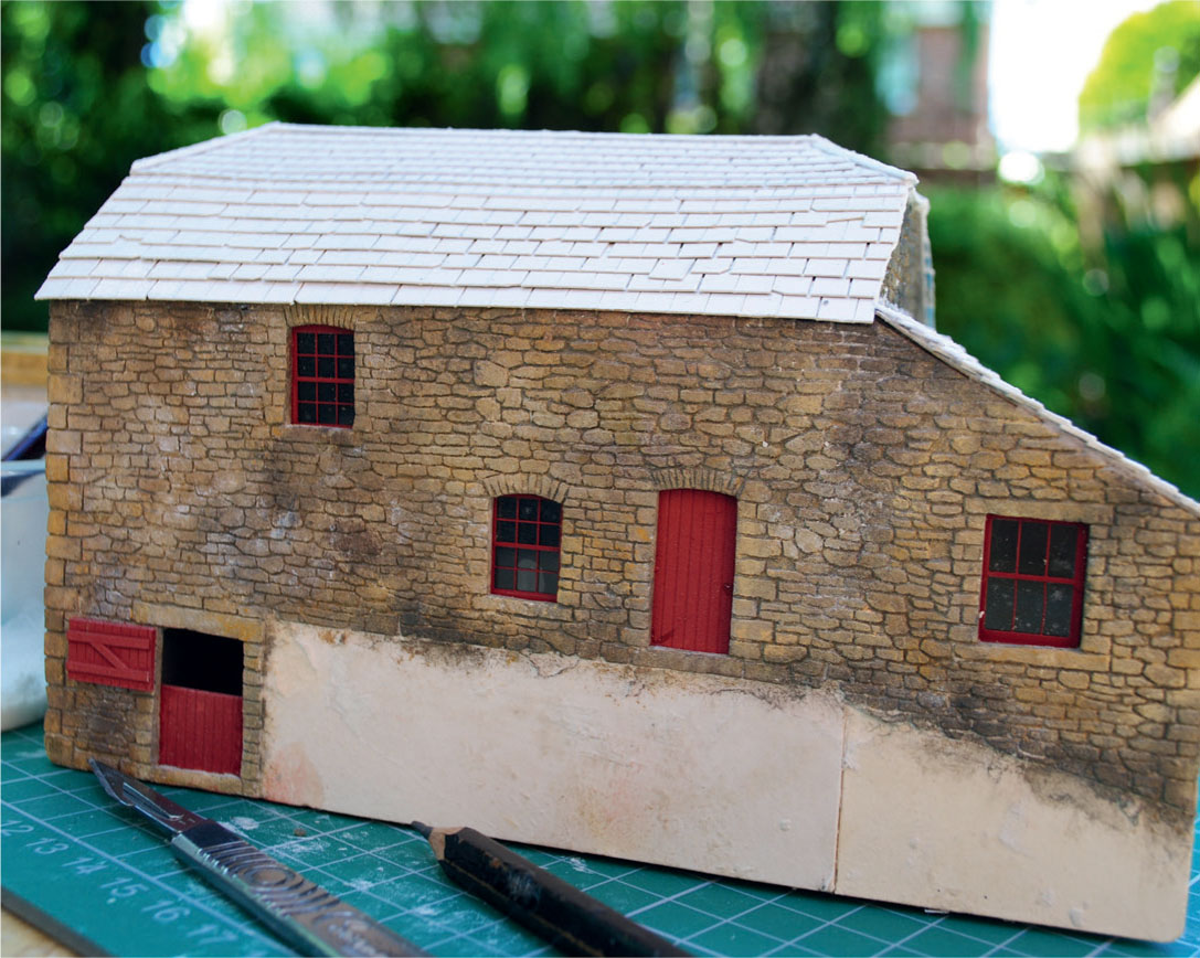
The elevations to form the shell of the watermill have been cut out from mounting card and foamboard, ready for assembly.
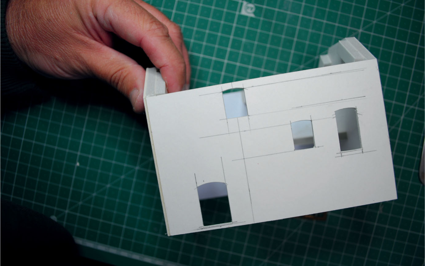
The assembled shell, showing all the window and door apertures cut out.
The shell of the building was then constructed, using foamboard for the gable ends. Offcuts of the foamboard were also used for corner and stretcher braces to give the building some rigidity and make supports to hold the roof. With all the walls now complete, the next stage was to add the masonry using a thin skin of Das modelling clay. The Das was added thinly into a bed of PVA, making sure that the corners were neatly finished. The clay was now left to air dry for about twenty-four hours before scribing could begin.
Before this, however, the apertures would need to be cleaned out with a small file and the corners sanded clean. The scribing started with the corner quoins and the lintels above the windows and the doors. After this the infill of rubble stone was scribed using a scalpel fitted with a 10A blade. The scribing process always creates a fair amount of powdered clay debris that will require brushing away with a toothbrush as progress is made.
When the scribing was completed attention turned to painting the building. The first stage was to add all the mortar using a wash of Payne’s Grey oil paint. This was followed by using a dry brushing technique to build up the colour added to the face of the masonry. The colours mixed to achieve this were the same as those given for painting the bridge in Project 3 of the previous chapter.
All the walls were painted before fitting the windows and the doors. The brass etchings selected for the windows were spray painted with Halfords Red Oxide primer. Strips of double-sided tape were added to the rear to make a fixing for the glazing material. The completed windows could now be fixed into the waiting apertures. The doors and any framework needed were made up using pre-grooved styrene sheet. The doors were then painted in the same Red Oxide before being fitted into position.
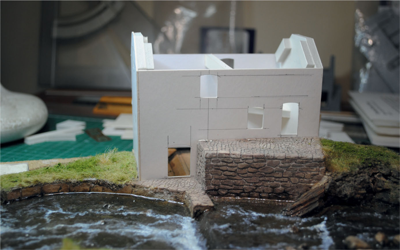
The shell has here been positioned onto the footings prepared on the diorama.
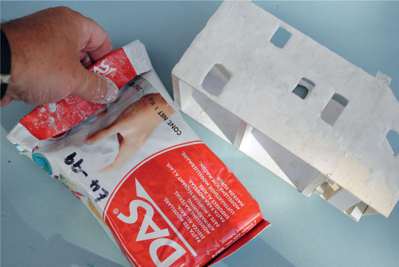
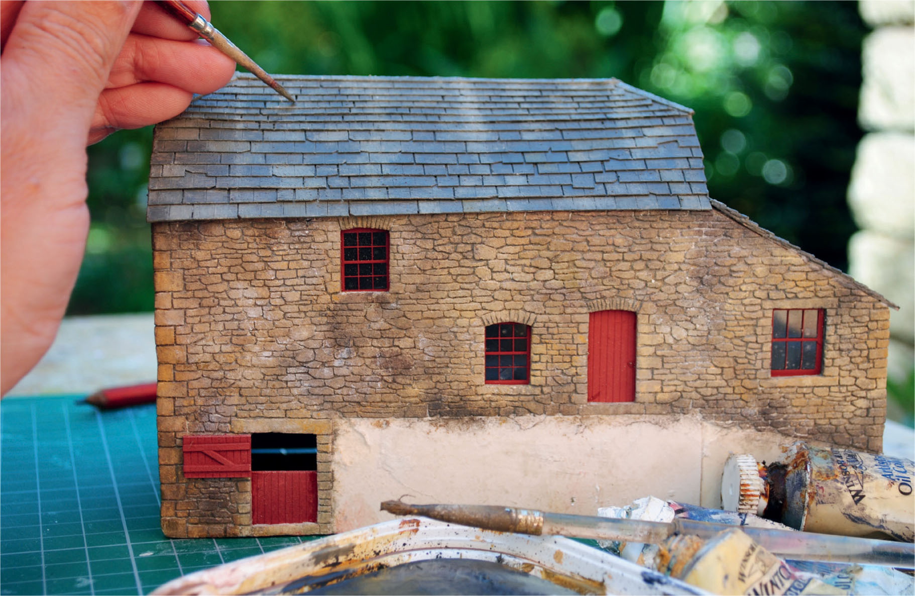
The masonry was created using Das modelling clay.
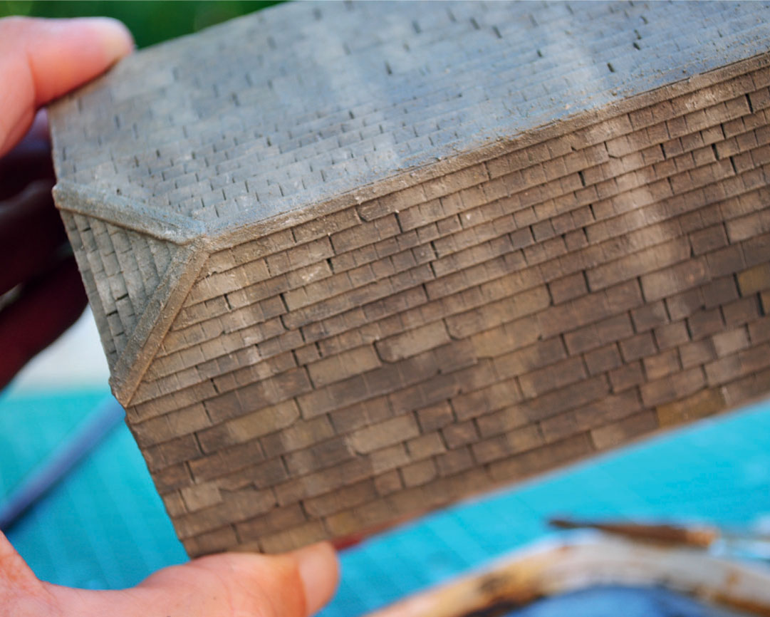
Seen from above, the roof has been added to the model, complete with slates made from Christmas cards.
The masonry has been painted using the dry brush technique. The windows and doors have been painted using Red Oxide spray paint.
The slates have been painted all over using a Matt Tank Grey from the Humbrol military spray range. Individual slates were then picked out in various shades of grey using a brush.
Applying rain staining to the roof adds to the general weathering of this building.
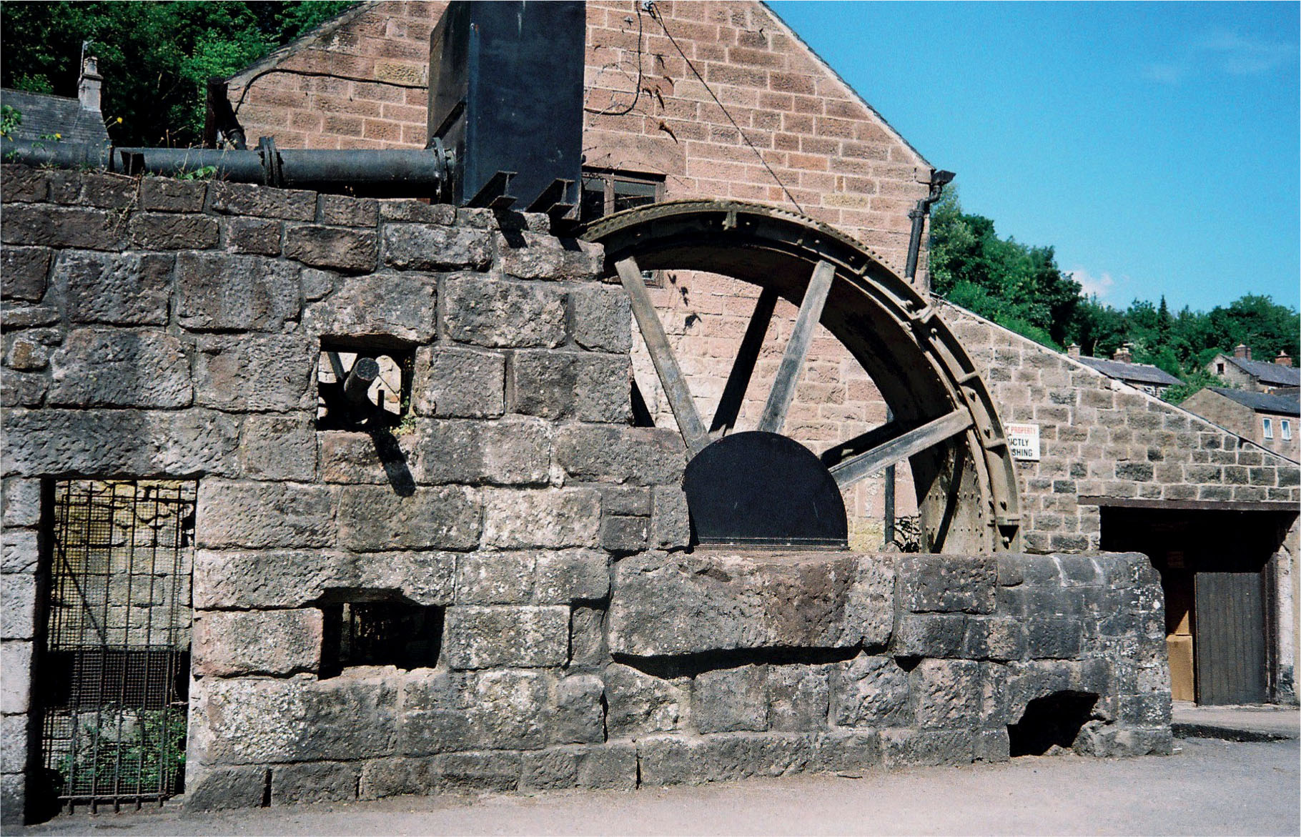
The prototype wheel on which that of the mill was based was at Cromford in Derbyshire.
The next stage would be to fabricate the mansard roof, using artist’s mounting card to make up a sub-base, first marking it out and then cutting it to shape. The main gable roof was fitted first. Two triangles were then cut to make the hipped ends. Once all the roof panels were secured to the sub-base, it was time to replicate the slate covering required.
Recycled greeting cards were used for the slates, marking them out first on the inside of the cards. These were cut into strips, with each individual slate cut to about two-thirds of the depth of the marked strip. Larger slates were cut first for adding to the lower section of the roof. The rest of the slates were cut to around a third of the size; these would complete the rest of the roof together with the hipped ends. The slates were fitted to the roof in the usual overlapping pattern and all the ridges were coped with a folded strip of card.
The first stage in painting was to mask off all the completed walls before applying a base coat of Humbrol Matt Tank Grey acrylic spray paint. Work could then begin on picking out the individual slates using different shades of grey mixed from oil paints. Payne’s Grey was next brushed all over the slates to blend them together.
The inspiration for this model came from Melin Bompren corn mill, now rebuilt at St Fagans National Museum of History.
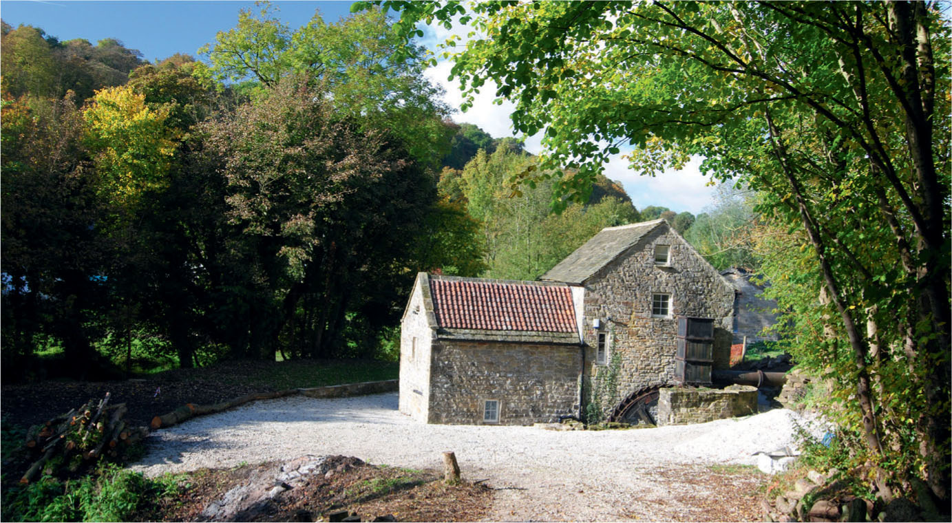
The centrepiece of a OO9 narrow gauge model railway project now under construction will be based on Fallgate Mill, near Ashover.
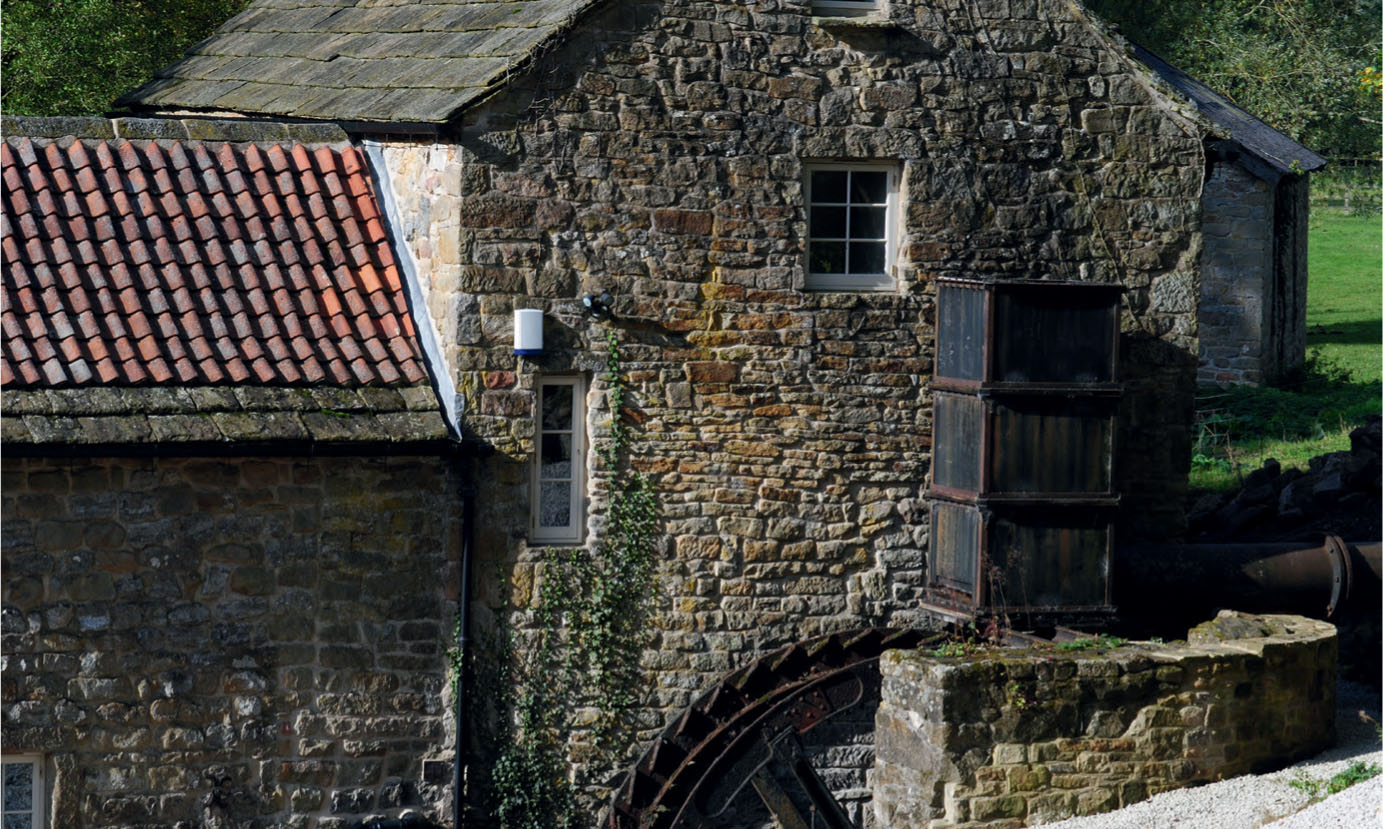
The rubble stone masonry used to construct Fallgate Mill. Photographs taken at the site will be a valuable reference source when constructing the model.
The finishing touches required adding all the weathering to the roof, applying rain staining by dragging a finger in a straight line down through the nearly dry grey paint. The lichens growing on the ridge and the edges were stippled on with a brush with cut-down bristles. Nearly dry Yellow Ochre oil paint was used for most of the lichens, together with some light green.
The second mill featured is still under construction as the centrepiece of a model railway project. The stone watermill alongside the River Amber at Fallgate, near Ashover, Derbyshire, was originally built for grinding corn. The redundant mill was acquired by the Clay Cross Company in 1918 and the machinery was put to use again crushing fluor spar for iron smelting. This period was chosen as a siding was provided in 1925 to link it to the nearby Ashover Light Railway.
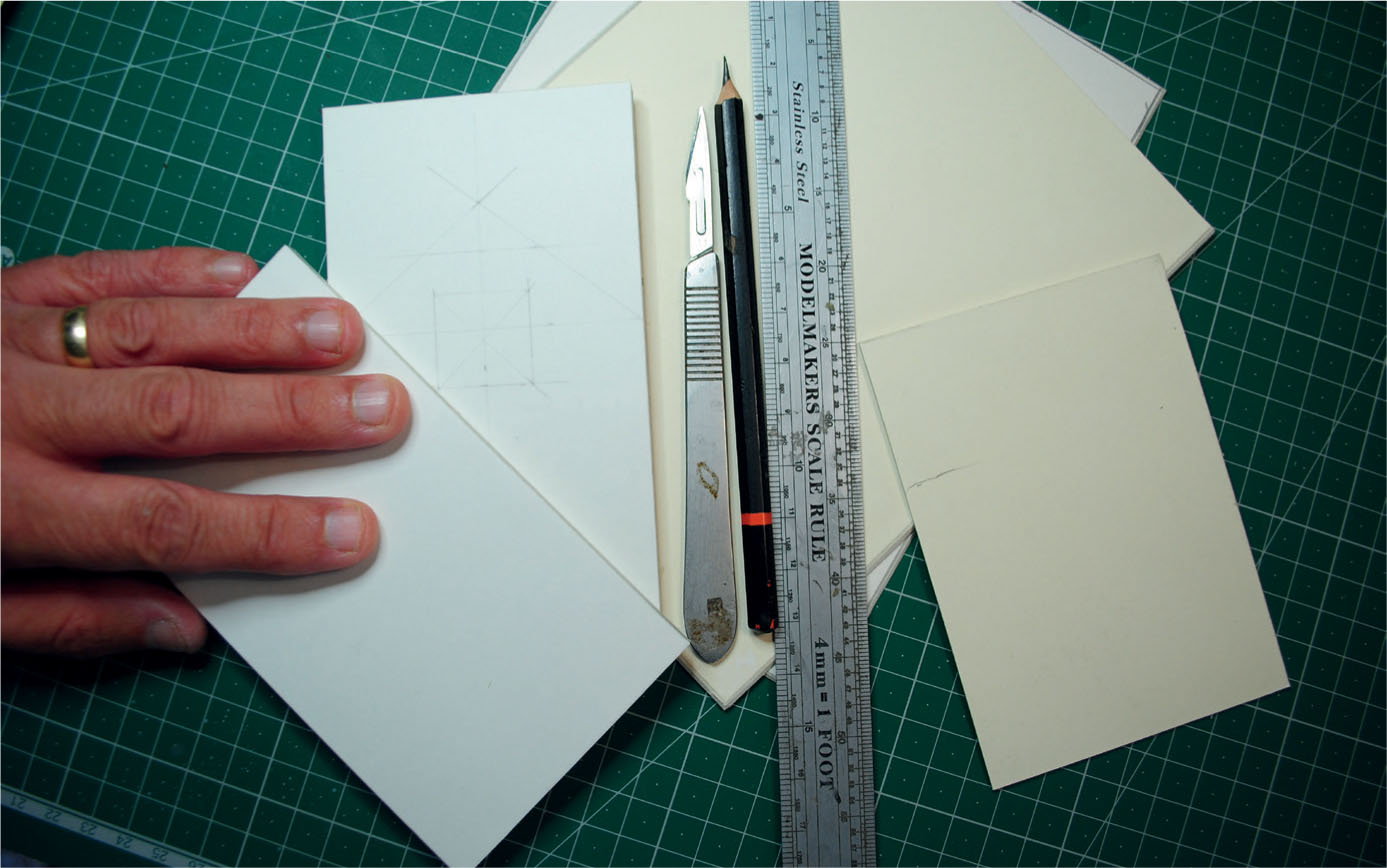
Scrap pieces of card are first selected for the model.
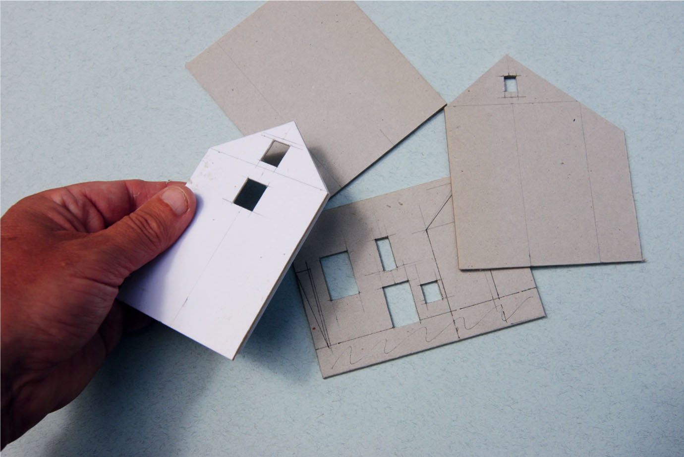
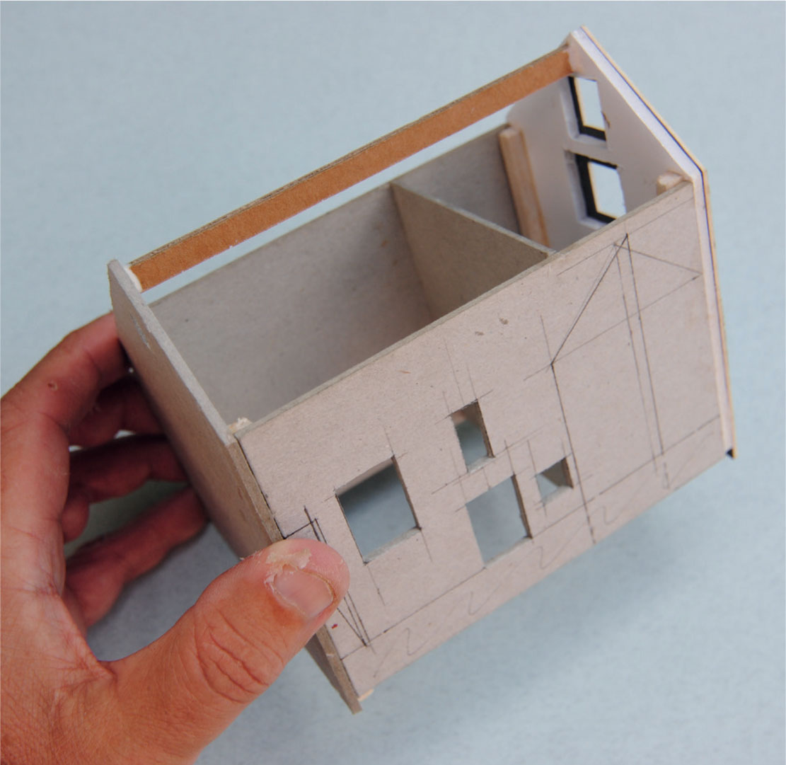
The elevations of the mill have been cut out ready for assembly.
The mill’s location meant that this model would have deep foundations, especially at the south gable end where the wheel pit was situated. Rigid cardboard was originally used as a backing board to contain the sheets of a sketch pad. The elevations were marked out on the card, working from measurements taken on site and from literature supplied by an estate agent (the building has been renovated as a private residence). A scale of 3.5mm to the foot was chosen as the building was going to be situated at the rear of the small OO9 gauge layout.
The wall profiles were all cut to include the extra depth of the foundations. The window and door apertures were cut out at the same time. The shell of the building was then assembled using square balsa wood strip on the inside of the corners, together with pieces of backing card for stretcher braces. The building was in three parts: the main mill itself and two smaller extensions, one on the front and the other added to the north gable end. The three parts were built up as separate units and would be brought together at a later stage.
The next stage was to create a skin for the stone masonry of the main building and the front extension only, as the other extension was constructed of brick. A thin skin of Das modelling clay was applied into the usual bed of PVA, which had been brushed on first. The clay was pushed in with fingers, keeping them wet to achieve the desired thickness. The clay was carefully sculpted around the corners of the building before being left to air dry for at least twenty-four hours.
Once dry, work could start on scribing the stonework, beginning at the corners and then scribing in the lintels, sills and any other structural stonework features. Once this had been successfully carried out according to reference photographs taken on site, the rest of the rubble infill could then be scribed out, once more matched to the photographs.
The shell of the mill has here been assembled, using balsa strip in the corners to join the walls together.
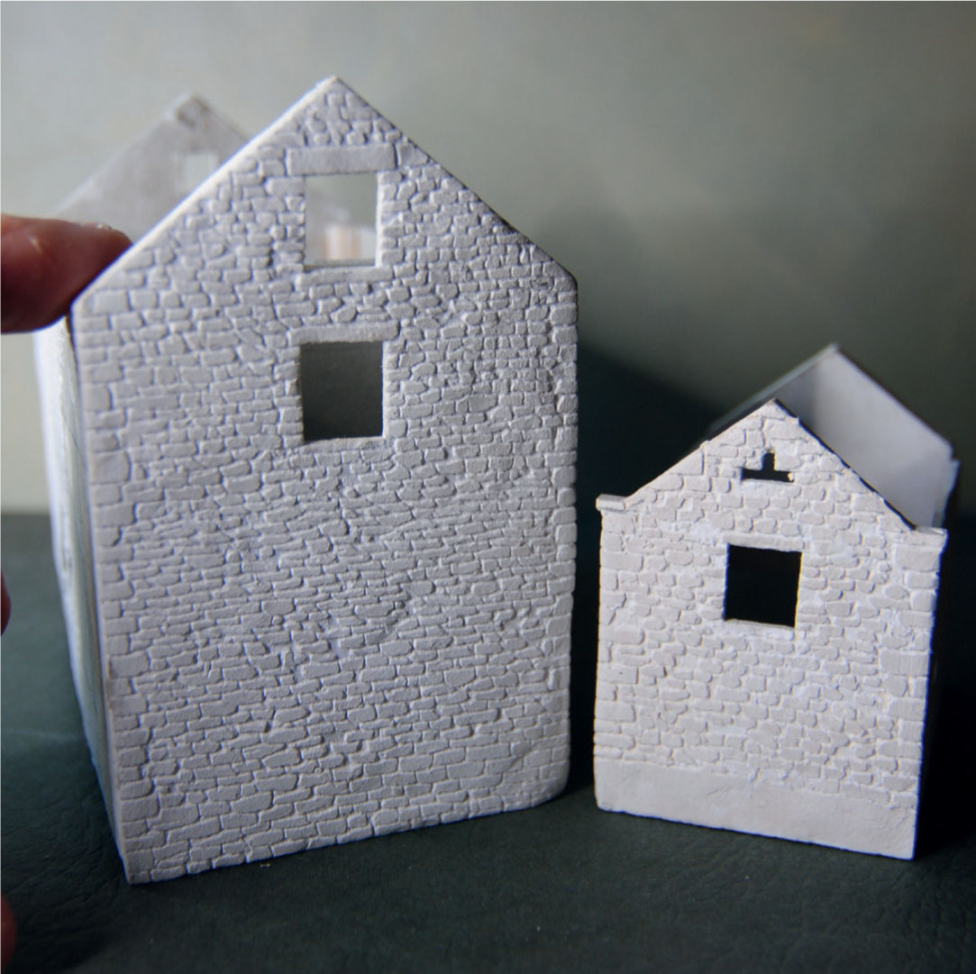
After adding a skin of Das modelling clay, the rubble stone masonry has been replicated on the gable end of the mill and the front extension.
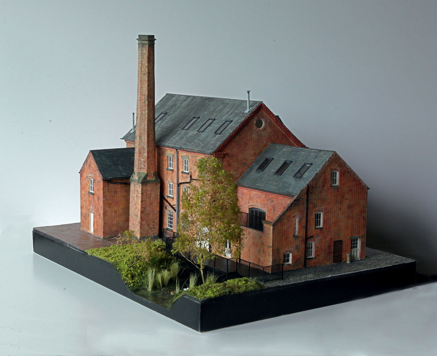
This model of Hilton Mill was constructed from card, with the brick masonry replicated using embossed styrene sheet. Like Bretby Mill, seen earlier, this has a boilerhouse and chimney for when the mill was converted to steam power.
CONCLUSION
This is as far as the model has progressed at the time of writing. It is intended to use a weathered brick printed sheet from the Redutex range to replicate the brickwork of the smaller extension. Greetings cards of various thicknesses will be used for the stone flags and the slates covering the roof areas. The painting process will be almost the same as described previously, except this time Derbyshire limestone and millstone grit will have to be replicated. It is hoped that the model will be completed by late 2018, along with the rest of the layout, and will be on display soon after.