This chapter covers the following subjects:
When the networks that eventually evolved into what we now call the Internet were first launched, they were the exclusive realm of academics and researchers. And when Vint Cerf and Bob Kahn invented TCP/IP for these networks, no one envisioned the Internet as it now is. At the time a 32-bit address space, yielding almost 4.3 billion addresses, seemed inexhaustible.
But as the kids who worked with these networks in college went out into the “real world,” they took with them an appreciation of the possibilities for what could be done with a peer-to-peer network built on open standards. Increasingly useful network applications began cropping up, and recognition of the value of corporate connections to a public network began the push for a commercial Internet. At the same time that all this was happening, desktop computers were becoming common not only in the office but, most significantly, in the home. Yet modems were not a common accessory on those early home computers because few home users saw the value of being connected to a public network.
That changed with the advent of the World Wide Web. Suddenly, easy acquisition and sharing of information exponentially increased the value of desktop computers as a tool for nontechnical users. As a result, in less than 20 years the Internet has changed the way we communicate, do business, and learn. It has made the world a much smaller place, and has had profound impact on world economics and politics.
But this explosion in the size and diversity of the “Internet population” has introduced, along with daily nuisances such as spam and viruses, a serious technical concern: The once inexhaustible supply of IPv4 addresses has become distinctly finite.
The problem of IPv4 address exhaustion was recognized in the early 1990s, when various experts made projections showing that if the increasing rate of the allotment of IPv4 addresses continued, the entire address space could be depleted in just a few short years. A new version of IP—known in the development stage as IP Next Generation or IPng, and which is now IPv6—was the proposed solution. But it was recognized that developing the new standards would take time, and that a short-term solution to IPv4 address depletion also was needed.
That short-term solution was Network Address Translation (NAT), which allows multiple hosts to share one or a few public IP addresses. Behind the NAT device, private IP addresses as specified in RFC 1918, and which you see in most examples in this book, are used. NAT has been so successful in slowing IPv4 address depletion, and has become such a standard part of most networks, that to this day many still question the need for a new version of IP. But the widespread use of NAT has changed the open, transparent, peer-to-peer Internet into something much more like a huge collection of client-server networks. Users are seen as being connected around the “edge” of the Internet, and services flow out to them. Seldom do users contribute to the overall wealth of the Internet. Seen from a more economic perspective, Internet users have become consumers only, not producers.
Although most of the IPv6 standards were completed years ago, it is only recently that serious interest in migrating from IPv4 to IPv6 has been shown. There are two fundamental drivers behind the growing recognition of the need for IPv6. The first is widespread vision of new applications using core concepts such as mobile IP, service quality guarantees, end-to-end security, grid computing, and peer-to-peer networking. NAT stifles innovation in these areas, and the only way to get NAT out of the way is to make public IP addresses abundant and readily available.
The second fundamental driver for IPv6 is the rapid modernization of heavily populated countries such as India and China. A compelling statistic is that the number of remaining unallocated IPv4 addresses is almost the same as the population of China: about 1.3 billion. With its aggressive expansion of its Internet infrastructure, China alone in the near future will represent an unsupportable pressure on an already strained IPv4 address pool. In India, with a population size close to China’s, 4- and 5-layer NAT hierarchies exist just to support the present demands for IP addresses.
IPv6 replaces the 32-bit IPv4 address with a 128-bit address, making 340 trillion trillion trillion IP addresses available. That number will meet the demands for public IP addresses, and answer the needs of the two fundamental drivers discussed here, well into the foreseeable future.[1]
IPv6 addresses are different from IPv4 addresses in far more ways than just their length. The “shorthand” for writing them is different, they have significantly different formats, and their functional organization is different. This section introduces you to those differences.
You certainly already know that 32-bit IPv4 addresses are represented by breaking them into four 8-bit segments and writing each of those segments in decimal between 0 and 255, separating them with periods; hence the term dotted decimal.
128-bit IPv6 addresses are represented by breaking them up into eight 16-bit segments. Each segment is written in hexadecimal between 0x0000 and 0xFFFF, separated by colons. An example of a written IPv6 address is
3ffe:1944:0100:000a:0000:00bc:2500:0d0b
Remembering more than a few such addresses is practically impossible, and writing them is not much fun either. Fortunately, there are two rules for reducing the size of written IPv6 addresses. The first rule is
The leading zeroes in any 16-bit segment do not have to be written; if any 16-bit segment has fewer than four hexadecimal digits, it is assumed that the missing digits are leading zeroes.
In the example address, the third, fourth, fifth, sixth, and eighth segments have leading zeroes. Using the first address compression rule, the address can be written as
3ffe:1944:100:a:0:bc:2500:d0b
Notice that only leading zeroes can be omitted; trailing zeroes cannot, because doing so would make the segment ambiguous. You would not be able to tell whether the missing zeroes belonged before or after the written digits.
Notice also that the fifth segment in the example address is all zeroes, and is written with a single zero. Many IPv6 addresses have long strings of zeroes in them. Take, for example, the following address:
ff02:0000:0000:0000:0000:0000:0000:0005
This address can be reduced as follows:
ff02:0:0:0:0:0:0:5
However, using the second rule can reduce this address even further:
Any single, contiguous string of one or more 16-bit segments consisting of all zeroes can be represented with a double colon.
Using this rule, the example address can be represented as the following:
ff02::5
The increased convenience in writing such an address is obvious. But notice that the rule says only a single contiguous string of all-zero segments can be represented with a double colon. Using the double colon more than once in an IPv6 address can create ambiguity. Take, for example, the following address:
2001:0d02:0000:0000:0014:0000:0000:0095
Either of the following reductions of the address is correct because they use a double colon only once:
2001:d02::14:0:0:95
2001:d02:0:0:14::95
But the following reduction is illegal because it uses the double colon twice:
2001:d02::14::95
It is illegal because the length of the two all-zero strings is ambiguous; it could represent any of the following IPv6 addresses:
2001:0d02:0000:0000:0014:0000:0000:0095
2001:0d02:0000:0000:0000:0014:0000:0095
2001:0d02:0000:0014:0000:0000:0000:0095
Unlike IPv4, in which the prefix—the network portion of the address—can be identified by a dotted decimal or hexadecimal address mask or a bitcount, IPv6 prefixes are always identified by bitcount. That is, the address is followed by a forward slash and a decimal number indicating how many of the first bits of the address are the prefix bits. For example, the prefix of the following address is the first 64 bits:
3ffe:1944:100:a::bc:2500:d0b/64
When you are writing just an IPv6 prefix, you set all the host bits to 0 the same way you do with IPv4 addresses. For example
3ffe:1944:100:a::/64
An IPv6 address consisting of all zeroes can be written simply with a double colon. There are two cases where an all-zeroes address is used. The first is a default address, discussed in Chapter 12, "Default Routes and On-Demand Routing," in which the address is all zeroes and the prefix length is zero:
::/0
The second all-zeroes IPv6 address is an unspecified address, which is used in some Neighbor Discovery Protocol procedures described later in this chapter. An unspecified address is a filler, indicating the absence of a real IPv6 address. When writing an unspecified address, it is differentiated from a default address by its prefix length:
::/128
The three types of IPv6 address follow:
• Unicast
• Anycast
• Multicast
Unlike IPv4, there is no IPv6 broadcast address. There is, however, an “all nodes” multicast address, which serves essentially the same purpose as a broadcast address.
A unicast address is an address that identifies a single device. A global unicast address is a unicast address that is globally unique. The general format of the IPv6 unicast address is shown in Figure 2-1. This format, specified in RFC 3587, obsoletes and simplifies an earlier format that divided the IPv6 unicast address into Top Level Aggregator (TLA), Next-Level Aggregator (NLA), and other fields. However, you should be aware that this obsolescence is relatively recent and you are likely to encounter some books and documents that show the old IPv6 address format.
Figure 2-1. The IPv6 general unicast address format.
The host portion of the address is called the Interface ID. The reason for this name is that a host can have more than one IPv6 interface, and so the address more correctly identifies an interface on a host than a host itself. But that subtlety only goes so far: A single interface can have multiple IPv6 addresses, and can have an IPv4 address in addition, in which case the Interface ID is only one of that interface’s several identifiers.
Perhaps the most striking difference between IPv4 addresses and IPv6 addresses, aside from their lengths, is the location of the Subnet Identifier as a part of the network portion of the address rather than the host portion. A legacy of the IPv4 address class architecture is that the subnet portion of an IPv4 address is taken from the host portion of the address. As a result, the host portion of the IPv4 address varies not only with its class, but also with the number of bits you use for subnet identification.
The immediate benefit of making the IPv6 Subnet ID field a part of the network portion of the address is that the Interface ID can be a consistent size for all IPv6 addresses, simplifying the parsing of the address. And making the Subnet ID a part of the network portion creates a clear separation of functions: The network portion provides the location of a device down to the specific data link and the host portion provides the identity of the device on the data link.
The Interface ID of the global IPv6 address is, with very few exceptions, 64 bits long. Also with very few exceptions, the Subnet ID field is 16 bits (Figure 2-2). A 16-bit Subnet ID field provides for 65,536 separate subnets; it seems that using a fixed Subnet ID size such as this, when in most cases the capacity will not be nearly fully used, is wasteful. But given the overall size of the IPv6 address space, and given the benefits of easy address assignment, design, management, and parsing that comes from using a fixed size, the waste is justified.
Figure 2-2. The standard field sizes of the global unicast IPv6 address.
The IANA and the Regional Internet Registries (RIRs)[2] assign IPv6 prefixes—normally /32 or /35 in length—to the Local Internet Registries (LIRs). The LIRs, which are usually large Internet Service Providers, then allocate longer prefixes to their customers. In the majority of cases, the prefixes assigned by the LIRs are /48. There are, however, as mentioned in the previous paragraph, a few exceptions in which the LIR might assign a prefix of a different length:
• If the customer is very large, a prefix shorter than /48 might be assigned.
• If one and only one subnet is to be addressed, a /64 might be assigned.
• If one and only one device is to be addressed, a /128 might be assigned.
The first few bits of the address specify the address type. For example, the first three bits of all global unicast addresses currently are 001. As a result, recognizing the hexadecimal representations of global unicast addresses is fairly easy: They all start with either 2 or 3, depending on the value of the fourth bit in the global routing prefix. So, for instance, currently allocated prefixes used by the 6Bone (the public IPv6 research network) begin with 3ffe, and IPv6 addresses currently allocated by the RIRs begin with 2001.
Binary 001 is expected to suffice for global unicast addresses for some time to come; a few other bit combinations are assigned to other defined address types, and the majority of leading bit combinations are reserved. Table 2-1 lists the currently allocated leading bit combinations, and the following subsections describe the other major IPv6 address types.
Table 2-1. High-order bits of IPv6 address types.
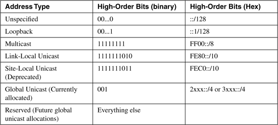
When we talk of global unicast addresses, we mean an address with global scope. That is, an address that is globally unique and can therefore be routed globally with no modification.
IPv6 also has a link-local unicast address, which is an address whose scope is confined to a single link. Its uniqueness is assured only on one link, and an identical address might exist on another link, so the address is not routable off its link. As you can see in Table 2-1, the first 10 bits of the link-local unicast address are always 1111111010 (FE80::/10).
As subsequent sections in this chapter demonstrate, link-local addresses have great utility for functions such as the Neighbor Discovery Protocol that communicates only on a single link. It also allows devices that are on links that do not have assigned global prefixes, or devices that do not yet know the global prefix assigned to the link, to create IPv6 addresses that allow them to communicate with other devices on the link. The section "Address Autoconfiguration" shows how link-local prefixes are used in this situation.
IPv6 originally defined a site-local unicast address in addition to the link-local address. A site-local address is unique only within a given site; devices in other sites can use the same address. Therefore a site-local address is routable only within the site to which it is assigned. Site-local IPv6 addresses are, then, functionally similar to private IPv4 addresses as defined in RFC 1918.
Advocates of site-local addresses cite several applications. One prominent application is for network operators that wish to use NAT, even with IPv6 addresses, to maintain independence of their address architecture from that of their service providers. Site-local addresses are also key to several proposed IPv6 multihoming mechanisms.
However, the IETF IPv6 Working Group determined that site-local unicast addresses introduced a number of difficulties. Not the least of the difficulties is the fact that the definition of a “site” is vague and can mean different things to different network administrators. Another problem is concern over, like RFC 1918 IPv4 addresses, the administrative difficulties introduced when such addresses are mistakenly “leaked” outside of their intended site boundaries. Other potential problems cited include increased complexity for applications and routers that must recognize and cope with site-local addresses. As a result of these concerns, and after some heated debate, the IPv6 Working Group deprecated site-local addresses in RFC 3879. An assurance has been given to those who see advantages in site-local addresses to introduce another scheme with similar “bigger scope than link but smaller scope than global” benefits, but as of this writing such a replacement scheme has yet to be seen.
The first 10 bits of site-local unicast addresses, as shown in Table 2-1, is 1111111011 (FEC0::/10).
An anycast address represents a service rather than a device, and the same address can reside on one or more devices providing the same service. In Figure 2-3, some service is offered by three servers, all advertising the service at the IPv6 address 3ffe:205:1100::15. The router, receiving advertisements for the address, does not know that it is being advertised by three different devices; instead, the router assumes that it has three routes to the same destination and chooses the lowest-cost route. In Figure 2-3 this is the route to server C with a cost of 20.
Figure 2-3. An anycast address represents a service that might appear on multiple devices.
The advantage of anycast addresses is that a router always routes to the “closest” or “lowest-cost” server.[3] So servers providing some commonly used service can be spread across a large network and traffic can be localized or scoped to the nearest server, making traffic patterns in the network more efficient. And if one server becomes unavailable, the router routes to the next nearest server. In Figure 2-3, for example, if server C becomes unavailable due to a network or server failure, the router chooses the path to server A as the next-lowest-cost route. From the router’s viewpoint, it is just choosing the next-best route to the same destination.
Anycast addresses are defined by their service function only, not by format, and theoretically might be any IPv6 unicast address of any scope. However, there is a format for reserved anycast addresses, defined in RFC 2526. Anycast addresses have been used for some time in IPv4 networks, but are formalized in their definition in IPv6.
A multicast address identifies not one device but a set of devices—a multicast group. A packet being sent to a multicast group is originated by a single device; therefore a multicast packet normally has a unicast address as its source address and a multicast address as its destination address. A multicast address never appears in a packet as a source address.
The members of a multicast group might include only a single device, or even all devices in a network. In fact, IPv6 does not have a reserved broadcast address like IPv4, but it does have a reserved all-nodes multicast group, which is essentially the same thing: a multicast group to which all receiving devices belong.
Multicasting is essential to the basic operation of IPv6, particularly some of its plug-and-play features such as router discovery and address autoconfiguration. These functions are a part of the Neighbor Discovery Protocol, discussed later in this chapter.
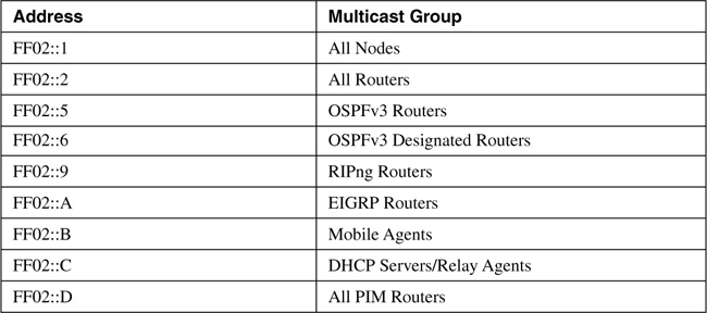
The format of the IPv6 multicast address is shown in Figure 2-4. The first eight bits of the address are always all ones, and the next four bits are designated as flags. Currently the first three of these bits are unused and always set to 0. The fourth bit indicates whether the address is a permanent, well-known address (0) or an administratively assigned transient address (1). The next four bits indicate the scope of the address as shown in Table 2-2. Table 2-3 shows several reserved, well-known IPv6 multicast addresses, all of which are link-local scope. Because a multicast group is always a set of individual nodes, there is no need—or sense—for having a subnet field in the multicast address. So the last 112 bits are used as the Group-ID, identifying individual multicast groups. Current usage sets the first 80 bits to 0 and just uses the last 32 bits.
Figure 2-4. The IPv6 multicast address format.
Table 2-2. Multicast address scopes.
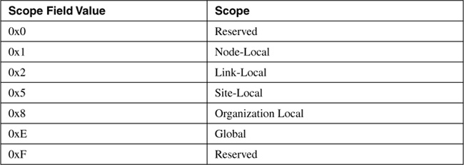
Table 2-3. Examples of well-known IPv6 multicast addresses.
There are several transition technologies—means of helping to transition a network from IPv4 to IPv6 or otherwise help IPv4 and IPv6 to coexist—that require an IPv4 address to be communicated within an IPv6 address. The individual technology specifies how the IPv4 address is to be embedded in the IPv6 address, and the implementation of the technology knows where among the 128 bits of the IPv6 address to find the 32 bits of the IPv4 address. But you will also find that many of these technologies have unique formats for their address representations that allow you to identify the embedded IPv4 address. Examples of IPv6 addresses with an embedded IPv4 address of 10.23.1.5 are
FE80::5EfE:10.23.1.5 (An ISATAP address)
::FFFF:10.23.1.5 and ::FFFF:0:10.23.1.5 (SIIT addresses)
FEC0:0:0:1::10.23.1.5 (TRT address)
In each of these examples, the IPv4 address is the last 32 bits of the IPv6 address and is represented in dotted decimal.
Other transition technologies using embedded IPv4 addresses do not use dotted decimal but encode the IPv4 address into hexadecimal. 6to4, for example, does this. 10.23.1.5 in hexadecimal is 0A17:0105. A 6to4 prefix with 10.23.1.5 embedded is then
2002:0A17:0105::/48
Transition technologies are not covered in this volume, and so you are not likely to see one of these address representations again in this book. They are shown here only because you are likely to encounter addresses like these if you work with IPv6.
The format of the IPv6 packet header is shown in Figure 2-5. There are some distinct similarities and some differences—some distinct, some subtle—with the IPv4 packet header shown in Figure 1.2 of the previous chapter.
Figure 2-5. The IPv6 packet header.
Version is, as with the IPv4 header, a four-bit field indicating the IP version. Here, of course, it is set to binary 0110 to indicate version 6.
Traffic Class is an eight-bit field that corresponds to the eight-bit IPv4 ToS field. But given the evolution of the ToS field over the years, both are now used for Differentiated Class of Service (DiffServ). So even though there is a correspondence of this field with the old ToS field, its name more accurately reflects the current usage of the values carried here.
Flow Label is a field unique to IPv6. The intention of this 20-bit field is to allow labeling of particular flows of traffic; that is, packets that are not just originated by the same source and going to the same destination, but that belong to the same applications at the source and destination. There are several advantages to differentiating flows, from providing a finer-grained differentiated class-of-service treatment to ensuring, when balancing traffic loads across multiple paths, that packets belonging to the same flow are always forwarded over the same path to prevent possible reordering of packets. Flows (or more accurately, microflows) typically are identified by a combination of source and destination address plus source and destination port.
But to identify the source and destination port, a router must look beyond the IP header and into the TCP or UDP (or other transport-layer protocol) header, adding to the complexity of the forwarding process and possibly affecting router performance. Finding the transport layer header in an IPv6 packet can be especially problematic because of extension headers, described in the next section. An IPv6 router must step through possibly many extension headers to find the transport-layer header.
By marking the Flow Label field appropriately when the packet is originated, routers can identify a flow by looking no further than the packet header. As of this writing, however, the complete specification of how to use the flow label field is still being debated, and routers currently ignore the field. It nevertheless holds promise of allowing IPv6 to provide better Quality of Service (QoS) features than IPv4 for applications such as Voice over IP (VoIP).
Payload Length specifies the length of the payload, in bytes, that the packet is encapsulating. Recall from Chapter 1, "TCP/IP Review," that IPv4 headers, because of the Options and Padding fields, can vary in length. Therefore, to find the payload length in an IPv4 packet, the value of the Header Length field must be subtracted from the Total Length field. The IPv6 packet header, on the other hand, is always a fixed length of 40 bytes, and so the single Payload Length field is enough to find the beginning and end of the payload.
Next Header specifies which header follows the IPv6 packet header. In this, it is very similar to the Protocol field in the IPv4 header and, in fact, is used for the same purpose when the next header is an upper-layer protocol header. Like that IPv4 field, this field is also eight bits. But in IPv6, the header following the packet header might not be an upper-layer protocol header, but an extension header (again, described in the next section). So the Next Header field is named to reflect this wider range of responsibility.
Hop Limit corresponds exactly, both in length (eight bits) and function, to the IPv4 Time to Live (TTL) field. As you read in Chapter 1, the original intention of the TTL field was that it would be decremented by the number of seconds a packet is queued in a router during forwarding, but that this function was never implemented. Instead, routers decrement the TTL by one no matter how long the packet is queued (and in modern networks it is highly unusual for a packet to be queued anywhere near as long as one second). Therefore, the TTL has always been a measure of the maximum router hops a packet can take on its way to a destination. If the TTL decrements to 0, the packet is discarded. Hop Limit is used for exactly the same, but is named more appropriately for this function.
Source and Destination Address correspond to the IPv4 Source and Destination fields, except of course these fields are 128 bits each to accommodate IPv6 addresses.
Noticeably missing from the IPv6 header is a Checksum field like that of the IPv4 header. Given the overall increase in reliability of modern transport media—wireless perhaps being a notable exception—along with the fact that upper-layer protocols usually carry their own error-checking and recovery mechanisms, checksumming of the IPv6 header itself adds little value, and is therefore eliminated.
Comparing the IPv6 header in Figure 2-5 with the IPv4 header in Figure 1.2, you can see that although the Source and Destination Address fields are each four times as long in the IPv6 header, the IPv6 header itself is not that much larger than an IPv4 header: 40 bytes for IPv6 versus a minimum of 20 bytes for IPv4. If extensive use is made of the IPv4 Options field, although unusual, the IPv4 header can actually be larger than the IPv6 header.
Also notice that in addition to the Options field, other fields that are not always used, such as those associated with fragmentation, are eliminated from the IPv6 header. So given its fixed length and exclusion of all fields that do not carry information necessary for the forwarding of every packet, the IPv6 header is both compact and efficient.
But what if you do want to use one of those optional IP features, such as fragmentation or source routing or authentication? When an optional function is used in IPv6, an extension header appropriate for the function is added after the packet header. If, for example, source routing, fragmentation, and authentication options are to be used, three extension headers formatted to carry the information needed for each of those functions are added as shown in Figure 2-6. Because of these headers, efficiency is added to IPv6 packets in two ways:
• The packet carries only the information required by that individual packet. No unused fields are carried.
• New optional functions can be added to the IPv6 packet by defining new extension headers.
Figure 2-6. Extension headers allow IPv6 packets to carry all the information required for that packet, but only the information required for that packet.
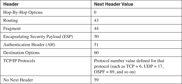
Each extension header, like the IPv6 header, has a Next Header field. So each header tells which header follows it. Table 2-4 shows the currently defined extension headers and their next header values. So, for example, in Figure 2-7, the Next Header value in the IPv6 header indicates that the next header is a Routing extension header (43), that header’s Next Header field indicates that the next header is a Fragmentation extension header (44), and so on. The last extension header, AH, indicates that the next header is a TCP header (Protocol Number 6).
Table 2-4. Next Header values.
Figure 2-7. The Next Header field in the IPv6 header and each extension header specifies which header follows it.
The format of each of the extension headers is described in RFC 1883. But briefly, the function of each extension header is as follows:
• Hop-By-Hop Options—carries information that must be examined by every node along the forwarding path, such as Router Alert and Jumbo Payload options.
• Routing—provides source routing functionality by listing nodes that the packet must pass through on the way to its destination.
• Fragment—is used when a packet is fragmented, to provide the information necessary for the receiving node to reassemble the packet. A significant difference between IPv4 and IPv6 is that only originating nodes can fragment packets; IPv6 routers do not fragment the packets. So originating nodes must either use Path MTU Discovery (PMD) to find the lowest MTU along a path to the destination, or never produce packets larger than 1280 bytes. PMD is described in the next section. IPv6 specifies that all links on which it runs must be able to support packet sizes of at least 1280 bytes so that originators can use the minimum-size option rather than PMD if they so choose.
• Encapsulating Security Payload (ESP)— is used when the payload is encrypted.
• Authentication Header (AH)— is used when the packet must be authenticated between the source and destination.
• Destination Options— carries information to be examined only by the destination node or possibly by nodes listed in the Routing header.
RFC 1883 also specifies the order in which extension headers, if they are used, should appear. The only hard-and-fast rule here is that if the Hop-By-Hop Options header is used, it must directly follow the IPv6 header so that it can be easily found by the transit nodes that must examine it. The recommended extension header order is as follows:
1 IPv6 Header
2 Hop-By-Hop Options
3 Destination Options (only if intermediate routers specified in the Routing header must examine this header)
4 Routing
5 Fragment
6 Authentication
7 Encapsulating Security Payload
8 Destination Options (if only the final destination must examine this header)
9 Upper-Layer Header
IPv6 requires a control protocol for exchanging and processing error and informational messages, just as IPv4 does. And like IPv4, it uses ICMP to do this. But the ICMP used by IPv6 is not the same ICMP as used by IPv4. Although ICMP for IPv4 has a Protocol Number of 1, ICMPv6 for IPv6 has a Next Header value of 58.
ICMPv6 is specified in RFC 2463. Many of the functions defined in this RFC are the same ones defined for ICMP for IPv4; but there are many ICMP messages, such as Source Quench and Timestamp, that have no equivalent in ICMPv6.
Comparing the ICMPv6 header shown in Figure 2-8 to the ICMP header shown in Figure 1.28, you can see that they are identical. And like ICMP, ICMPv6 uses a combination of type and code values to identify general types and then subtypes under them. The values defined in RFC 1885 are listed in Table 2-5.
Figure 2-8. The ICMPv6 header format.
Table 2-5. ICMPv6 Message Type and Code fields.
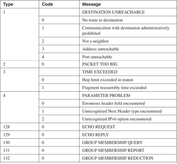
In addition to the basic error and informational functions of ICMPv6, there are mechanisms that use the ICMPv6 messages. For example, the Path MTU Discovery mechanism mentioned in the previous section sends packets of increasing size to a destination. When the smallest MTU of the links on the path to the destination is exceeded by a given packet size, the packet is dropped and a Packet Too Big message is sent to the source address; the source then knows the smallest MTU on the path. And, as with IPv4, Echo and Echo Reply messages are used by the Ping function.
But in addition to basic error and information messages, there is a separate set of ICMPv6 messages defined that are used by an essential IPv6 protocol: the Neighbor Discovery Protocol, described in the next section.
The most distinct characteristics of IPv6 after its increased address space are its plug-and-play features. Neighbor Discovery Protocol (NDP) is the enabler of these plug-and-play features, using the following functions:
• Router Discovery— A node can discover, when it is connected to an IPv6 link, the local routers without the aid of Dynamic Host Configuration Protocol (DHCP).
• Prefix Discovery— A node can discover, when it is connected to an IPv6 link, the prefix or prefixes assigned to that link.
• Parameter Discovery— A node can discover parameters such as the link MTU and hop limits for its connected link.
• Address Autoconfiguration— A node can determine its full address, again without the aid of DHCP.
• Address Resolution— A node can discover the link-layer addresses of other nodes on the link without the use of Address Resolution Protocol (ARP).
• Next-Hop Determination— A node on a link can determine the link-layer next hop for a destination, either as a local destination or a router to the destination.
• Neighbor Unreachability Detection— A node can determine when a neighbor on a link, either another host or a router, is no longer reachable.
• Duplicate Address Detection— A node can determine if an address it wants to use is already being used by another node on the link.
• Redirect— A router can notify a host of a better next-hop than itself to an off-link destination. The redirect function is a part of basic ICMP functionality in IPv4, but is redefined as part of NDP in IPv6.
NDP messages should always be link-local in scope, and therefore the packets encapsulating them always use either link-local IPv6 addresses or multicast addresses with a link-local scope. To add a further layer of security, the Hop Limit of the IPv6 packet carrying all NDP messages is 255. If one of these packets is received with a Hop Limit less than that value, it means the packet has passed through at least one router, and the packet is dropped. This prevents NDP from being attacked or spoofed from a source not attached to the local link.
NDP is defined in RFC 2461. It uses ICMPv6 to exchange the messages necessary for its functions; specifically, five new ICMPv6 messages are specified in RFC 2461:
• Router Advertisement (RA) messages are originated by routers to advertise their presence and link-specific parameters such as link prefixes, link MTU, and hop limits. These messages are sent periodically, and also in response to Router Solicitation messages.
• Router Solicitation (RS) messages are originated by hosts to request that a router send an RA.
• Neighbor Solicitation (NS) messages are originated by nodes to request another node’s link layer address and also for functions such as duplicate address detection and neighbor unreachability detection.
• Neighbor Advertisement (NA) messages are sent in response to NS messages. If a node changes its link-layer address, it can send an unsolicited NA to advertise the new address.
• Redirect messages are used the same way that redirects are used in ICMP for IPv4; they have merely been moved from being a part of the base ICMPv6 protocol to being a part of NDP.
Figure 2-9 shows the format of the Router Advertisement message. Its ICMPv6 type is 134 and the code is 0. The source address of the IPv6 packet encapsulating the RA is always the IPv6 link-local address of the interface from which the packet originates. The destination address is either the all-nodes multicast address (FF02::1) if the RA is a periodic transmit, or the link-local address of the soliciting node if the RA is sent in response to a Router Solicitation.
Figure 2-9. The Router Advertisement message format.
Hop Limit indicates the value of the Hop Limit field that nodes attached to the link should give to any packets they originate on the link. If no Hop Limit is specified by this router, the field is set to all zeroes.
M is the Managed Address Configuration flag. If this bit is set, the originating router is telling hosts on the link to use stateful address autoconfiguration via DHCPv6. If the flag is cleared, hosts on the link should use stateless address autoconfiguration. Address autoconfiguration is described later in this chapter.
O is the Other Stateful Configuration flag. When set, the originating router is telling hosts on the link to use DHCPv6 for the acquisition of other link information. The M and O flags can be used together. For example, by clearing the M flag but setting the O flag, the router is telling hosts to use stateless address autoconfiguration but then consult a DHCPv6 server for other configuration parameters.
Router Lifetime is set to a value other than 0 only if the originating router is a default router. In that case, this field specifies the lifetime of the default router in seconds, up to a maximum value of 18.2 hours.
Reachable Time is used by the Neighbor Unreachability Detection function of NDP. It specifies the time, in milliseconds, that a node should assume a neighbor is reachable after the node has confirmed reachability of the neighbor.
Retransmit Timer is used by the Address Resolution and Neighbor Unreachability Detection functions of NDP. It specifies the minimum time, in milliseconds, between retransmitted Neighbor Solicitation messages.
Possible options that can be carried in the Options field of the RA include the following:
• The link-layer address of the interface from which the RA is originated.
• An MTU specification for the link.
• One or more prefixes assigned to the link. This information is essential to stateless address autoconfiguration, telling hosts on the link what the link prefixes are.
Figure 2-10 shows the format of the Router Solicitation message. Its ICMPv6 type is 133 and the code is 0. The source address of the IPv6 packet encapsulating the RS is either the IPv6 address assigned to the originating interface or, if no address has been assigned (as would be the case if the originating host is beginning address autoconfiguration), an unspecified address of :: (all zeroes). The destination address is the all-routers multicast address (FF02::2).
Figure 2-10. The Router Solicitation message format.
The Options field can contain the link-layer address of the originating interface, if it is known. However, the source link-layer address must not be included if the source address of the encapsulation packet is unspecified, such as when the originator is soliciting a router during address autoconfiguration.
Figure 2-11 shows the format of the Neighbor Solicitation message. Its ICMPv6 type is 135 and the code is 0. The source address of the IPv6 packet encapsulating the NS is either the IPv6 address assigned to the originating interface or, if the NS is sent for Duplicate Address Detection, the unspecified address of :: (all zeroes). The destination address is either a solicited-node multicast address corresponding to the target address, or the target address.
Figure 2-11. The Neighbor Solicitation message format.
Target Address is the IPv6 address of the target of the solicitation. The target address is never a multicast address.
The Options field of the NS can contain the link-layer address of the originating interface.
Figure 2-12 shows the format of the Neighbor Advertisement message. Its ICMPv6 type is 136 and the code is 0. The source address of the IPv6 packet encapsulating the NS is always the IPv6 address assigned (or autoconfigured) to the originating interface. The destination address is either the source address of the packet containing the NS to which the NA is sent in response, or the all-nodes multicast address (FF02::1).
Figure 2-12. The Neighbor Advertisement message format.
R is the Router flag. When set, it indicates that the originator is a router. This bit is used during Neighbor Reachability Detection to detect a router that has changed to a host.
S is the Solicited flag. This bit is set when the NA is sent in response to an NS.
O is the Override flag. When set, it indicates that the information in the NA should override any existing neighbor cache entry and update the cached link-layer address. When the O bit is cleared the NA will not override an existing neighbor cache entry.
Target Address is, when the NA is sent in response to a NS, the address in the Target Address field of the NS. If the NA is unsolicited (that is, sent to advertise a change of the originator’s link-layer address), the Target Address is the originator’s address.
The Options field of the NA can contain the target link-layer address—that is, the link-layer address of the NA’s originator.
Figure 2-13 shows the format of the Redirect message. Its ICMPv6 type is 137 and the code is 0. The source address of the IPv6 packet encapsulating the Redirect is always the link-local IPv6 address of the interface from which the message is originated. The destination address is always the source address of the packet that triggered the redirect.
Figure 2-13. The Redirect message format.
Target Address is the address of the better first-hop—usually the link-local address of another router on the link.
Destination Address is the IPv6 address of the destination that is redirected to the target address.
The Options field of the Redirect message can contain the link-layer address of the target, and as much of the header of the packet that triggered the redirect, without making the redirect packet exceed 1280 bytes.
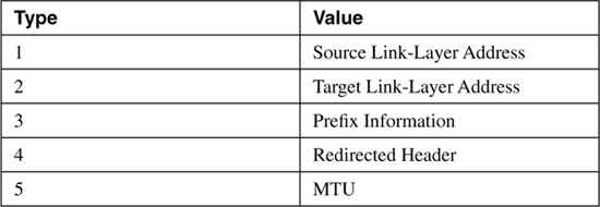
The Options field of all of these five messages, when it contains any information, consists of one or more Type/Length/Value (TLV) triplets. Each TLV consists, as shown in Figure 2-14, of an 8-bit Type field specifying the type of information carried in the value field, an 8-bit Length field specifying the length in units of 8 octets of the value field, and the variable length Value field.
Figure 2-14. The format of the TLVs used in the Options fields of the NDP messages.
Table 2-6 shows the possible values and their associated type numbers. The format of the individual value fields is not provided in this chapter; consult RFC 2461 for the details on the value fields.
Table 2-6. Value fields and their types.
A router makes its presence known, along with any parameters it has been configured to advertise, by periodically sending RAs on its attached links. Presumably the links on which the RA do the most good are broadcast links such as Ethernet, where hosts can receive the RAs and thus learn necessary information about the link.
RFC 2461 specifies that the period between transmissions of RAs should be between 4 and 1800 seconds, with a default of 600 seconds. It also specifies a minimum period between advertisements of RAs with a default of 200 seconds. The advertisements are jittered between the maximum and minimum values to prevent synchronization on a link.
These unsolicited RAs are sent with their source address set to the link-local IPv6 address of the router’s interface. The destination address is the all-nodes multicast address (FF02::1).
Cisco routers automatically send RAs on Ethernet and FDDI interfaces whenever IPv6 is enabled on the router with the command ipv6 unicast-routing. The default interval is 200 seconds, and can be changed with the command ipv6 nd ra-interval. The Router Lifetime of the transmitted RAs is 1800 seconds by default, and can be changed with the command ipv6 nd ra-lifetime. If you do not want a router to be a default router on a link, you can use this command to set the Router Lifetime value to 0. The default Reachable Time of the RAs is 0 (which means unspecified), and can be changed with the command ipv6 nd reachable-time. The Retransmit Timer field is set to a default of 0 ms (unspecified) and can be changed with the command ipv6 nd ns-interval. The M and O flags can be set with the commands ipv6 nd managed-config-flag and ipv6 nd other-config-flag, respectively. If you do not want an interface to transmit RAs at all, you can disable them with the command ipv6 nd suppress-ra.
By default, Cisco routers include in the RAs all IPv6 prefixes configured on the originating interface. You can control the prefixes advertised, and parameters associated with those prefixes, with the command ipv6 nd prefix.
Of course, 200 seconds is a long time for a host that has just attached to an interface to wait for an RA so that it can find the routers and learn the link parameters. So when a host first becomes active on a link, it can send an RS to solicit the immediate transmission of an RA. The source of the RS can either be the unspecified address (::) or the host’s link-local IPv6 address. The destination is always the all-routers multicast (FF02::2).
When a router receives an RS, it sends (after a delay of .5 seconds) an RA in response. If the source address of the RS that triggered the RA is a host’s link-local address, the RA is unicast to the host using its link-local address. If the source address of the RS was unspecified, the solicited RA is multicast to the all-nodes address.
When a host receives an RA, it adds the router to its default router list (unless the RA indicates by a Router Lifetime value of 0 that it cannot be used as a default). If there is more than one router on the default router list, how the host selects a default router is implementation-specific. It could either rotate through the list, or select and keep a single router as default. In either instance, the Redirect function is essential for updating the host when a different default than the one it selected should be used.
When an IPv6 host first becomes active on a link, it can self-configure its own interface address. The first step in this process is the determination of the 64-bit Interface ID portion of the address. On broadcast interfaces (where hosts are most likely to appear), a mechanism called MAC-to-EUI64 conversion is used. Quite simply, this mechanism takes the 48-bit Media Access Control (MAC) address of the interface—which can normally be assumed to be globally unique—and converts it into a 64-bit Interface ID by inserting a reserved 16-bit value of 0xFFFE into the middle of the MAC address and “flipping” the Universal/Local (U/L) bit of the MAC address to 1 (Universal).
Figure 2-15 illustrates this process. A MAC address, 0000:0B0A:2D51, is to be converted. The first step, shown in binary for easier understanding of what is happening, is to “split” the MAC address in the middle and insert 0xFFFE between the two 24-bit halves. The address is now 64 bits long. Next, the U/L bit of the original MAC address—which is always the 7th bit—is flipped from 0 to 1. The resulting address, 0200:0BFF:FE0A:2D51, is now a valid 64-bit Interface ID.
Figure 2-15. MAC-to-EUI64 conversion is used to create a 64-bit Interface ID from an interface’s 48-bit MAC address.
Of course, the Interface ID is only half of the IPv6 address; a 64-bit prefix is also required. Recall from Table 2-1 that the link-local prefix is a reserved, well-known value of 0xFE80::/10. Using this as a full 64-bit prefix (0xFF80::/64), it can be added onto the derived Interface ID, and the host now has a complete IPv6 address that can be used for communication with other devices on the same link. For example, combining the link-local prefix with the Interface ID derived in Figure 2-15 gives a link-local address of FF80::0200:0BFF:FE0A:2D51. 2-The following shows an example of a link-local address, in this case from an Ethernet interface “en1” on a Macintosh OS X host. Using the link-local prefix FE80::/10 and a MAC-to-EUI64 conversion, an IPv6 interface derives its link-local address with no help from any other device:
[Jeff-Doyles-Computer:~] jdoyle% ifconfig en1
en1: flags=8863<UP,BROADCAST,SMART,RUNNING,SIMPLEX,MULTICAST> mtu 1300
inet6 fe80::211:24ff:fe23:334e prefixlen 64 scopeid 0x5
inet 10.10.24.13 netmask 0xffffff00 broadcast 10.10.24.255
ether 00:11:24:23:33:4e
media: autoselect status: active
supported media: autoselect
[Jeff-Doyles-Computer:~] jdoyle%
If the host only needs to communicate with devices on the link, autoconfiguring its link-local address is sufficient. But if it needs to communicate with devices off-link, it needs an address with a wider scope—normally a global IPv6 address. There are two ways it can acquire this address: stateful or stateless address autoconfiguration.
If a host uses stateful address autoconfiguration, it consults a DHCPv6 server for the necessary address information. It might either be preconfigured to find a DHCPv6 server, or a received RA might have its M flag set telling it to use DHCPv6. DHCPv6, described in RFC 3315, is not much different in its end results than DHCP for IPv4.
Much more interesting is stateless autoconfiguration. With this very simple process, the host acquires one or more link prefixes from the RAs it receives. It then adds the prefix to its previously determined Interface ID, and it now has a globally unique IPv6 address. For example, if the host from Figure 2-15 received an RA advertising a prefix of 3FFE: 1104:404:1::/64, it would add that prefix to its Interface ID for a global address of 3FFE:1104: 404:1:0200:0BFF:FE0A:2D51.
Although the use of MAC addresses to derive an Interface ID almost always guarantees a unique address of any scope, it is wise to ensure that the address is unique. So whenever a device acquires a unicast address, it must perform Duplicate Address Detection before using the address. It does not matter whether the address was acquired via stateful or stateless configuration, or if the address was statically configured. The only exception to the rule is an anycast address, because anycast addresses by definition can appear on more than one device. There is also an assumption that if a Duplicate Address Detection has been performed on a link-local address that has an Interface ID that was derived from MAC-to-EUI64 conversion, and if the address passes, other addresses using the same Interface ID will also be unique, and so the Duplicate Address Detection does not need to be repeated.
A node that has acquired a new address classifies the address as tentative. The address cannot be used until the Duplicate Address Detection operation has been completed with verification that no other node on the link uses that address. The node sends an NS with the Target Address field set to the address to be verified. The source address of the NS is the unspecified address, and the destination of the NS is a solicited-node multicast address.
A solicited-node multicast address is formed by prepending the prefix FF02:0:0:0:0:1: FF00::/104 to the last 24 bits of the target address. For example, given the Interface ID derived in Figure 2-15, the solicited-node multicast address is FF02::1:FF0A:2D51. The reason for this is that if a node has autoconfigured more than one interface address, the last 24 bits of all of its addresses should be the same. So the one NS with a solicited-node multicast address should match all of its interface addresses. More important, using a solicited-node multicast address ensures that if two nodes attempt to do a Duplicate Address Detection on the same address simultaneously, they will detect each other.
If a node receives an NS and the target address matches one of its assigned addresses, it sends an NA with the Target Address and the destination address set to the tentative address. The node that had originated the NS, on receipt of the NA, knows that the tentative address is duplicate and cannot be used.
You know from Chapter 1 that when an IPv4 node wants to communicate with another IPv4 node on a local link, it must first discover the destination’s link-layer (or data link) address. This address is then used as the destination address in the frame that encapsulates the IP packets to that node. For example, a node might want to send a packet to examplehost.com. A DNS query returns the address 3FFE:521:2400:15:211:24FF:FE23:334E. The sending node must now discover the link-layer address to use as a destination address of the frame for the local link. As the previous chapter discussed, IPv4 uses ARP for this discovery. IPv6, however, uses NDP.
When the node examines the prefix of the IPv6 address returned by DNS, it either concludes that the destination is a neighbor on the local link or that it is off-link and therefore reachable through the default router. If the latter is the case, the node should already know the link-layer address of the default router from the RAs. But if the destination is on the local link, the node first looks in its neighbor cache to see if the address is known. The neighbor cache in IPv6 is very similar to the ARP cache in IPv4; it records known network-layer addresses and the link-layer addresses associated with them. The following shows a neighbor cache from a Microsoft Windows XP host. The neighbor cache stores known IPv6 addresses and their associated link-layer addresses:
C:\Documents and Settings\Jeff Doyle>ipv6 nc
5: fe80::202:2dff:fe25:5e4c 00-02-2d-25-5e-4c permanent
4: fe80::260:83ff:fe7b:2df3 00-60-83-7b-2d-f3 stale (router)
4: fe80::210:a4ff:fea0:bc97 00-10-a4-a0-bc-97 permanent
4: 3ffe:3700:1100:1:210:a4ff:fea0:bc97 00-10-a4-a0-bc-97 permanent
4: 3ffe:3700:1100:1:d9e6:b9d:14c6:45ee 00-10-a4-a0-bc-97 permanent
4: 2001:468:1100:1:210:a4ff:fea0:bc97 00-10-a4-a0-bc-97 permanent
4: 2001:468:1100:1:d9e6:b9d:14c6:45ee 00-10-a4-a0-bc-97 permanent
3: 2002:c058:6301::c058:6301 192.88.99.1 permanent
3: 2002:836b:213c::836b:213c 131.107.33.60 permanent
3: 2002:4172:a85b::4172:a85b 127.0.0.1 permanent
3: 2002:836b:213c:1:e0:8f08:f020:6 131.107.33.60 permanent
3: 2001:708:0:1::624 incomplete
2: ::65.114.168.91 127.0.0.1 permanent
2: fe80::5efe:65.114.168.91 127.0.0.1 permanent
2: fe80::5efe:169.254.113.126 127.0.0.1 permanent
1: fe80::1 permanent
1: ::1 permanent
If the address is not in the neighbor cache, it is entered but tagged Incomplete, indicating that address resolution is in progress. The node then sends an NS to the solicited-node multicast address associated with the target node. The NS should include the Source Link-Layer option (type 1), so that the solicited node would have the link-layer address of the soliciting node, and therefore would know where to send the responding NA. If a value other than 0 is included in the RAs, multiple NSs can be sent at that specified interval. If the Retransmit Timer value in the RAs is unspecified (0), the NS is retransmitted every 1000 ms until an NA is received. If no NA is received from the solicited node after three NS transmissions, the neighbor address resolution has failed and an ICMP message of type 1/code 3 (Destination Unreachable/Address Unreachable) is returned for each packet queued for transmission to the now unknown destination.
If the solicited node exists and the NS is valid, it responds with an NA. The Target Address field of the NA is set to the value of the Target Address field of the NS that triggered it. The soliciting node, upon receipt of the NA, can add the target node’s link-layer address to the neighbor cache entry and change the entry from Incomplete to Reachable.
The neighbor cache of a Cisco router can be observed with the command show ipv6 neighbors, as shown in Example 2-1.
Example 2-1. The neighbor cache of a Cisco router can be displayed with the command show ipv6 neighbors.
Confucius# show ipv6 neighbors
IPv6 Address Age Link-layer Addr State Interface
2001:201:1502:1:210:a4ff:fea0:bc97 0 0010.a4a0.bc97 REACH Ethernet0
fe80::210:a4ff:fea0:bc97 0 0010.a4a0.bc97 REACH Ethernet0
fe80::260:83ff:fe4c:5df2 0 0060.834c.5df2 REACH Ethernet0
3ffe:1300:a47:20:d9e6:b9d:14c6:45ee 0 0002.2d25.5e4c REACH Ethernet1
The stateless address autoconfiguration has raised a security concern for some: Even if a device moves from subnet to subnet or even major network to major network, its Interface ID always remains the same; and if the Interface ID remains the same, it can be tracked. At the least, this becomes a privacy issue. For example, suppose you are using IPv6 to connect to your company network. Recording and analyzing packets coming into some part of the network can identify you by your unchanging Interface ID. And by further analyzing the different prefixes prepended to that Interface ID, your employer can infer where you are at all times: at work, at home, traveling, or whatever. More insidious uses can also be made of such tracking, keeping record of your location and activities for everything from marketing to criminal exploitation.
RFC 3041 addresses this security concern by defining IPv6 privacy addresses. A privacy address is one in which the Interface ID is generated by an algorithm using a pseudo-random number. What is significant about it, and makes it reasonably private, is that the Interface ID changes approximately once a day (or on some configurable period) and also whenever the node acquires a new IPv6 prefix.
Of course, a constantly changing address is not practical for reachability. Nodes that want to communicate with you, and hence DNS servers, must know you by only one or a few static addresses. So the standard statelessly configured IPv6 address remains your public address. Anyone wanting to send packets to you uses this address as the destination. But when you send packets back, you use the private address. This is a bit like having Caller ID in your home but blocking your number from appearing on anyone else’s Caller ID. You can see who is calling you, but others cannot see your number when you call them.
The following shows the addresses assigned to a Microsoft Windows XP machine. There are two public IPv6 addresses assigned to the interface, and you can see that although the prefixes are different, the MAC-to-EUI64–generated Interface IDs are the same. You can easily identify the public Interface IDs by the 0xFFFE inserted in the middle. But for both of these public addresses there is also a private address (which Windows labels as “anonymous"). These private addresses are created by prepending the RA-discovered IPv6 prefix onto the randomly generated Interface ID. Public and private (called “anonymous" here) are used together to create anonymity for the host but at the same time maintain reachability:
C:\Documents and Settings\Jeff Doyle>ipv6 if 4
Interface 4: Ethernet: Local Area Connection 2
uses Neighbor Discovery
uses Router Discovery
link-layer address: 00-10-a4-a0-bc-97
preferred global 2001:484:1200:1:d9e6:b9d:14c6:45ee,
life 6d21h14m26s/21h12m4s (anonymous)
preferred global 2001:468:1200:1:210:a4ff:fea0:bc97,
life 29d23h59m25s/6d23h59m25s (public)
preferred global 3ffe:3705:1200:1:d9e6:b9d:14c6:45ee,
life 6d21h14m26s/21h12m4s (anonymous)
preferred global 3ffe:3705:1200:1:210:a4ff:fea0:bc97,
life 29d23h59m25s/6d23h59m25s (public)
preferred link-local fe80::210:a4ff:fea0:bc97, life infinite
multicast interface-local ff01::1, 1 refs, not reportable
multicast link-local ff02::1, 1 refs, not reportable
multicast link-local ff02::1:ffa0:bc97, 3 refs, last reporter
multicast link-local ff02::1:ffc6:45ee, 2 refs, last reporter
link MTU 1500 (true link MTU 1500)
current hop limit 64
reachable time 22000ms (base 30000ms)
retransmission interval 1000ms
DAD transmits 1
The discussion of neighbor address resolution in a previous section made mention of neighbor cache entries being labeled as Incomplete or Reachable. In fact, a neighbor cache entry can be in one of five states:
• Incomplete— Neighbor address resolution is in progress. An NS has been sent to the solicited-node multicast address for the entry, but no NA has yet been received.
• Reachable— The address has been recently confirmed as reachable. "Recently confirmed" means that some indication of its reachability has been received within the time specified in the Reachable Time field of the RAs. If no Reachable Time has been specified in RAs, a default Reachable Time of 30 seconds is used.
• Stale— The Reachable Time has elapsed since the last positive confirmation of reachability with the destination has been received.
• Probe— A confirmation of reachability is being sought by sending NS to the destination every Retransmit Time or (if no Retransmit Time has been specified) every 1000 ms.
• Delay— An address is put into this state when a packet is sent to a destination that was in the Stale state. It stays in the Delay state for 5 seconds, and if no confirmation of reachability is received within that time, the state is changed to Probe. This state is an optimization to give upper-layer protocols a chance to confirm reachability before a probe NS is sent.
Reachability of a neighbor is confirmed in one of two ways:
• "Hints" from an upper-layer protocol, such as an ACK of a TCP message.
• A response to a probe of the destination address by soliciting an RA or NA. This is necessary because some upper-layer protocols, such as UDP, do not actively acknowledge the receipt of transmitted messages.
Neighbor Unreachability Detection confirms not just reachability from the neighbor’s perspective, but confirms two-way reachability from the local node’s perspective. For this reason, an unsolicited NA or RA cannot change the state of a neighbor cache entry to Reachable; the received message only indicates one-way reachability from the originating node to the local node. Two-way reachability is confirmed only by either a remote response to a transmitted message (such as an ACK of a TCP packet) or an RA or NA sent in response to a solicitation.
The purpose of this and the previous chapter was to examine the basics of IP in both of its versions. Understanding the basics of IP addressing and the fundamental processes of IP provides the foundation for understanding IP routing. The next chapter delves into the information a router needs to successfully and accurately forward a packet toward its destination.
1 What is the length of an IPv6 address?
2 How are IPv6 addresses represented?
3 What are the two rules for compacting IPv6 addresses?
4 Why is it illegal to use more than one double colon in an IPv6 address?
5 What is the difference between the IPv6 addresses ::/0 and ::/128?
6 What is the part of the unicast IPv6 address that specifies the host, and what is its length?
7 What is the length of the Subnet ID portion of the unicast IPv6 address?
8 If the first 10 bits of an IPv6 address are FF80::/10, what type of address is it?
9 What type of address is 3FFE:204:100:90::1?
10 What is an anycast address?
11 What is a multicast address?
12 What is the length of the IPv6 header?
13 What is the purpose of the Flow Label field in the IPv6 header?
14 To what field in the IPv4 header does the IPv6 Next Header field correspond?
15 To what field in the IPv4 header does the IPv6 Hop Limit field correspond?
16 In what way is the IPv6 Next Header field like the IPv4 Protocol Number field, and in what way is it different?
17 How do extension headers make IPv6 packets more efficient?
18 What is the Next Header value of ICMPv6?
19 What is the significant difference between IPv4 fragmentation and IPv6 fragmentation?
20 What are the five ICMPv6 messages used by the Neighbor Discovery Protocol?
21 What is the purpose of the M and O flags in the RA?
22 What is the purpose of the Reachable Time field of the RA?
23 What is the purpose of the Retransmit Timer field in the RA?
24 What is indicated if the Router Lifetime field in the RA is set to 0?
25 What is the purpose and effect of the S flag in the NA?
26 What is the difference between stateful and stateless address autoconfiguration?
27 What two steps does MAC-to-EUI64 conversion use to derive an Interface ID?
28 When a device acquires a unicast IPv6 address it must perform Duplicate Address Detection, with one exception. What is that exception?
29 What does the prefix FF02:0:0:0:0:1:FF00::/104 signify?
30 What does IPv6 use in place of ARP and an ARP cache?
31 What is a privacy address?
32 What does an Incomplete state of an entry in the neighbor cache signify?
33 What does a Probe state of an entry in the neighbor cache signify?
34 What two ways does Neighbor Unreachability Detection use to verify two-way reachability of a neighbor?