Chapter 3. Getting Somewhat More Serious
This third chapter of the book applies what you have learned so far to some finished projects. I’ll show you how to make a wearable version of the “pulsing glow” project from Experiment 11, and will take you through the initial development process of an intrusion alarm. Looking further ahead, in Chapter Four you’ll move into the world of integrated circuit chips.
The tools, equipment, components, and supplies described below will be useful in Experiments 12 through 15, in addition to items that have been recommended previously.
Necessary Items for Chapter Three
As before, when buying tools and equipment, see “Buying Tools and Equipment” for a shopping list. If you want kits containing components and supplies, see “Kits”. If you prefer to buy your own components from online sources, see “Components”. For supplies, see “Supplies”.
Essential: Power Supply
You could continue to use 9-volt batteries for all the projects in the book, but I am now classifying an AC adapter as essential, because it’s so much more convenient. Also, I think it should turn out to be cheaper than buying batteries, as you start to build circuits that take more power.
To convert AC current from an outlet in your home, you have three options:
A universal adapter such as the one in Figure 3-1 is the most versatile option, providing a switchable range of outputs. Typically these will include 3V, 4.5V or 5V, 6V, 9V, and 12V. Universal adapters are intended to power small devices such as voice recorders, phones, and media players. They may not deliver a perfectly smooth or accurate DC output, but you should be able to smooth the power yourself with a couple of capacitors, as I will illustrate when we get to a project that uses the adapter.
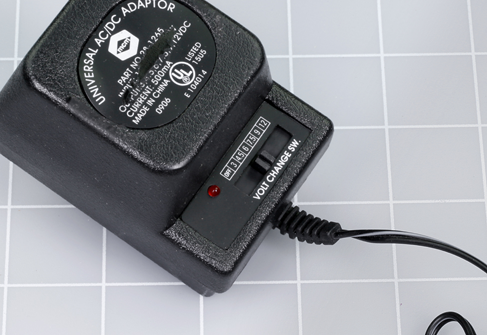
Figure 3-1. This AC adapter plugs into the wall and allows you a choice of DC voltages by moving a small switch.
Alternatively you can buy a single voltage AC adapter to deliver 9 volts DC, as shown in Figure 3-2. When you start using digital logic chips that require 5 volts, you can convert the 9 volts with a small, cheap component called a voltage regulator. (The regulator will also work with power from a 9-volt battery.)
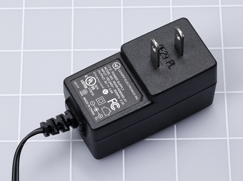
Figure 3-2. An AC adapter that delivers a fixed 9-volt DC output.
Your third option is to spend much more money on a proper benchtop power supply that provides variable DC outputs of 0V to +15V and 0V to −15V, plus a fixed 5V output. It should also have several breadboards mounted conveniently on top of its box. There is no doubt that this will be very useful if you continue into the field of electronics, but you may not feel sure about that yet.
If you decide to buy a universal adapter, see “Other Components” and scroll down to the part referring to Chapter Three of the book, for search instructions.
Whichever kind of adapter you buy, it must have these attributes:
-
The output must be DC, not AC. Almost all AC adapters give you a DC output, but there are a few exceptions.
-
Outputs must be rated for at least 500mA (which may be written as 0.5A).
-
It doesn’t matter what kind of plug is on the end of the DC power-output wire, because you’ll be cutting it off anyway.
-
For the same reason, if a universal adapter offers you a range of output plug adapters, don’t worry about what type they are, as you won’t be using them.
-
Very cheap AC adapters may become unreliable if you draw current up to their rated limit. In the United States, look for the UL symbol indicating certification from Underwriters Laboratories.
Essential: Low-Power Soldering Iron
While a breadboard is indispensable for putting together a circuit quickly to understand how it works, a soldering iron is necessary for making permanent electrical connections in a circuit that you want to keep. The soldering iron works by melting a thin wire composed of an alloy called solder until it forms a blob around the copper wires or components that you wish to join. When the solder cools, the joint becomes durable.
You don’t absolutely have to have a soldering iron. You can complete all the projects in this book just by breadboarding them. However, there is a special pleasure in building something durable, and soldering is a useful skill. For these reasons, I have categorized a soldering iron as “essential.”
Personally I like to have a low-power soldering iron for small parts that are vulnerable to excessive heat, and a separate general-duty soldering iron for heavier tasks (described immediately below). Some people prefer to use just one thermostatically controlled soldering iron for everything, but if it’s small, I don’t think it delivers the heat capacity that is sometimes required, and if it’s medium-sized, it isn’t so easy to use for delicate work. Also, a thermostatically controlled unit can be expensive.
A low-power soldering iron should be rated at 15W, and the smaller it is, the easier it is to handle. The tip should taper to a slender but rounded point, like a newly sharpened pencil. A plated tip is preferable, although the manufacturer may not state that the tip is plated. A well-used 15W soldering iron is shown in Figure 3-3. The discoloration is a normal consequence of heat, and does not degrade function.
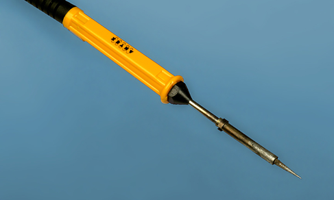
Figure 3-3. A low-wattage soldering iron designed for precise electronics work.
Essential: General Duty Soldering Iron
The limited heat capacity of a 15W soldering iron will be insufficient if you need to connect thicker wires, especially to components such as heavy-duty switches with terminals designed to handle substantial current. The terminals may sink heat so rapidly, the low-wattage iron will be unable to create a temperature high enough to melt solder. You may run into a similar situation when you try to attach a wire to a solder tab on a full-size potentiometer.
For these situations, you will need a soldering iron rated for 30 to 40 watts. While it is not required for most of the projects in this book, I do recommend it when you are creating your first solder joints, because the greater heat capacity will make the joints easier. A 30W iron is usually cheaper than a 15W iron, and represents a relatively small additional expense. I think a chisel-shaped tip enables better heat transfer, and since you will not be using this iron for delicate work, you don’t really need a pointed tip.
Soldering Iron Terminology
Some soldering irons have a desoldering pump built in, to help you undo a solder joint. This is a plunger which you pull with your fingers to suck a little air in through the tip of the iron. I don’t think it works very well. In any case, I have only seen it on 30W irons, which are too powerful to be used in many electronics applications.
A soldering iron may have the term “welding” in its product description. You can ignore the inaccurate use of this term, because soldering irons do not do welding in the usual sense.
A few soldering irons are packaged with a Helping Hand device that can hold small parts while you are working on them. This combination is worth considering, as it should cost less than if you buy the items separately. The Helping Hand device is described below.
If a soldering iron is sold with some solder included, don’t use it unless it is described as electrical solder that has a rosin core.
Many soldering irons are described as pencil type. The term is not very informative, because it can be applied either to a 15W or a 30W iron.
However, a pencil-type soldering iron is different in appearance from a pistol-grip soldering iron, such as the Weller Therma-Boost, shown in Figure 3-4. Some people prefer the ergonomics of this kind of grip, and the Therma-Boost has a nice quick-start feature that enables it to reach working temperature in less than a minute, making it ideal for someone who tends to be impatient. However, pistol-grip irons are all rated at 30W or higher, and tend to be more expensive than the ordinary pencil-type.

Figure 3-4. A Weller Therma-Boost 30W soldering iron can be useful when working with heavier wire and larger components.
Essential: Helping Hand
The so-called Helping Hand (sometimes known as a third hand) has two alligator clips that can hold components or pieces of wire precisely in position while you join them with solder. Some versions of the Helping Hand also feature a magnifying lens, a wire spiral in which you can rest your soldering iron, and a little sponge that you may use to clean the tip of your iron when it becomes dirty. These additional features are nice but not essential. See Figure 3-5.
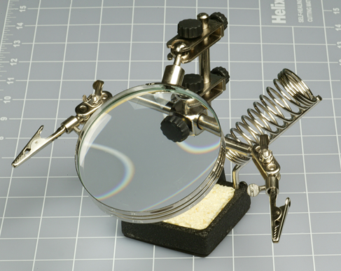
Figure 3-5. The Helping Hand, with additional accessories.
Essential: Magnifying Lens
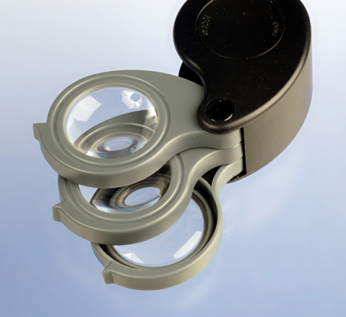
Figure 3-6. Handheld magnification is essential for inspecting solder joints.
No matter how good your eyes are, a small, handheld, powerful magnifying lens is essential when you are checking solder joints on perforated board. The three-lens set in Figure 3-6 is designed to be held close to your eye, and is more powerful than the large lens on a Helping Hand, which I do not find very useful. The folding lens in Figure 3-7 stands on your workbench for hands-free operation. Both are available from hobby stores or sources such as eBay and Amazon. Plastic lenses are quite acceptable if you are gentle with them.
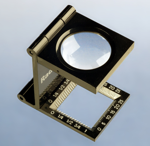
Figure 3-7. This kind of folding magnifier can stand on your desktop.
Optional: Clip-on Meter Test Leads
In previous experiments I have suggested that you can grab one of your meter probes with the alligator clip on a test lead, and use the alligator at the other end of the lead to grip a wire or a component.
A more elegant alternative is to buy a pair of “minigrabber” probes with little spring-loaded clips at the end. The Pomona model 6244-48-0 (shown in Figure 3-8) will do the job. However, this is a relatively expensive choice. You may prefer to look for meter leads that terminate in small alligator clips, such as those in Figure 3-9. These are usually the cheapest option. Or, you can just continue to use test leads in the manner that I suggested previously.
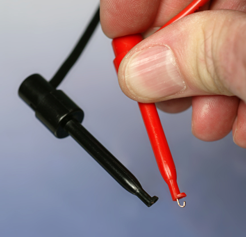
Figure 3-8. These “minigrabbers” on meter leads will grip wires or component leads.
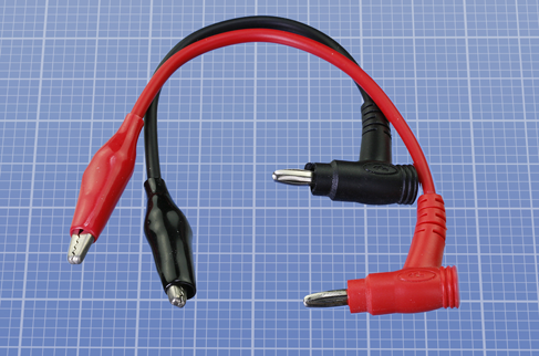
Figure 3-9. Meter leads that terminate in miniature alligator clips.
Optional: Heat Gun
If you join two wires with solder, you often need to insulate them. You can use electrical tape (sometimes called insulating tape), but it tends to come unstuck. A better option is heat-shrink tubing, which forms a safe, permanent sheath around a bare-metal joint. To make the tubing shrink, you use a heat gun, which is like a very powerful hair dryer. See Figure 3-10. They’re available from any hardware supply source, and I suggest you buy the cheapest one you can find.
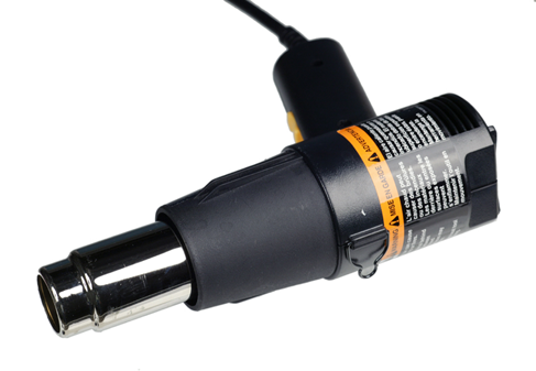
Figure 3-10. When a heat gun is applied to heat-shrink tubing, the tubing can create a snug, insulated sheath around bare wire.
For precise work, you may prefer to use a miniature heat gun, such as the one shown in Figure 3-11.
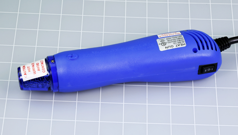
Figure 3-11. A miniature heat gun is slightly easier to handle than the full-sized type.
Optional: Desoldering Equipment
A desoldering pump is supposed to suck up hot, melted solder when you are trying to remove a solder joint that you made in the wrong place. See Figure 3-12. Some of my readers insist that this should be essential, not optional, but it’s a matter of taste. Personally if I make a soldering error, I prefer to snip it out and do it over.
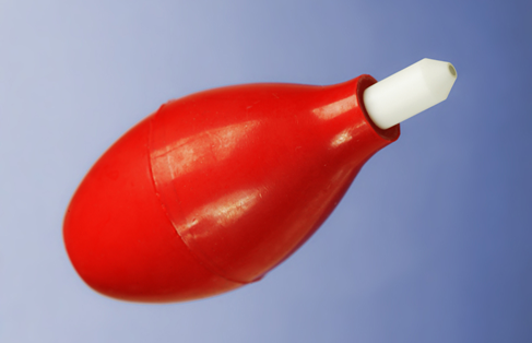
Figure 3-12. To remove a solder joint, you can suck melted solder into this squeezable rubber bulb.
Desoldering wick, also known as desoldering braid, is intended to soak up solder in conjunction with the solder pump. See Figure 3-13.
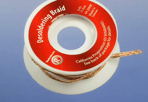
Figure 3-13. An additional option for removing liquid solder is to soak it up in this copper braid.
Optional: Soldering Stand
You place your hot soldering iron into a stand when you are not using it, in the same way that you would put a kitchen knife into a rack. See Figure 3-14. If you don’t want to spend the money on a stand, you can improvise a substitute, such as a piece of steel electrical conduit or even an old tin can nailed to a piece of wood. Or, you can rest the soldering iron on the edge of your work bench, and promise yourself to be veeery careful not to dislodge it. (Been there, done that.) When—not if—the soldering iron falls onto the floor, it will melt synthetic carpet or plastic floor tiles. Knowing this, you may attempt to catch it when you see it fall. If you grab it by the hot end, you will let go of it, so you might as well let it fall on the floor without the intermediate step of burning yourself.
Perhaps a soldering stand should be considered essential.

Figure 3-14. A safe and simple stand for a hot soldering iron. The yellow sponge can be wetted with water to clean the tip of the iron.
Optional: Miniature Hand Saw
Sooner or later, you may want to mount a finished electronics project in a decent-looking enclosure. For this purpose, you are likely to need tools to cut, shape, and trim thin plastic. For example, you may want to cut a square hole so that you can mount a square power switch in it.
Power tools are overkill for this kind of delicate work. A miniature handsaw (a.k.a. a “hobby saw”) is ideal for trimming things to fit. X-Acto makes a range of tiny saw blades. See Figure 3-15.
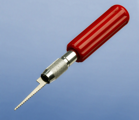
Figure 3-15. Useful for cutting small holes to mount components in plastic boxes.
Optional: Deburring Tool
A deburring tool instantly smooths and bevels any rough-sawn plastic or aluminum edge, and also can enlarge holes slightly. This may be necessary because some components are manufactured to metric sizes, which don’t fit in the holes that you drill with American bits. See Figure 3-16.
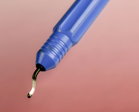
Figure 3-16. A deburring tool.
Optional: Calipers
These may seem like a luxury, but are very useful for measuring the external diameter of a round object (such as the screw thread on a switch or a potentiometer) or the internal diameter of a hole (into which you may want a switch or potentiometer to fit). See Figure 3-17. If you choose one that has a digital output powered by a button battery, it will be switchable between metric and inches.
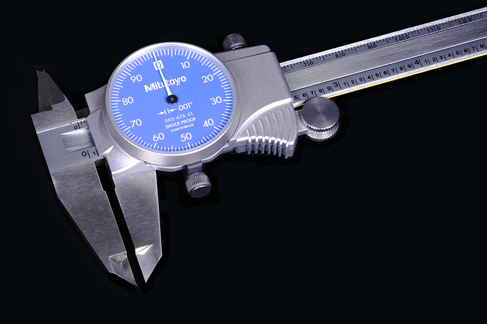
Figure 3-17. Calipers can measure internal and external diameters.
Supplies
While many of the tools that I listed are optional, supplies tend to be essential—unless you are absolutely positive that you never want to build a permanent version of a device. The tools and materials to build permanent projects will cost about the same as a month of cable TV. I think they’re a worthwhile investment.
Essential: Solder
This is the stuff that you will melt to join components together on a permanent (we hope) basis. It’s good to have very thin solder, 0.02” to 0.04” (0.5mm to 1mm) in diameter, for very small components. A range of solder thicknesses is shown in Figure 3-18. For projects in this book, a minimal amount of solder (half an ounce, or maybe three feet) will be sufficient.
Avoid buying solder that is intended for plumbers, or for craft purposes such as creating jewelry. The word “electronics” should appear in the manufacturer’s description of suitable purposes for the solder.
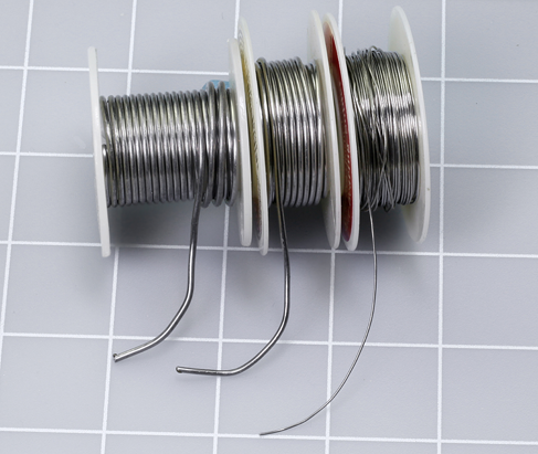
Figure 3-18. Spools of solder in various thicknesses.
There is some controversy about using solder that has lead in it. An experienced machinist assures me that this older type of solder makes better, easier joints at a lower temperature, and entails minimal health risk if used sparingly. He points out that lead-free solder has its own problems, as it contains more rosin, which creates more fumes. The issue has roused significant debate online, as you can see if you try this search:
lead tin solder safety
Personally, I lack the specialized knowledge to make a judgment call. I do know that if you live in the European Union, you’re not supposed to use solder with lead in it, for environmental reasons.
What you do definitely need is rosin-core solder intended for electronics use. Whether it contains lead is your choice.
Optional: Heat-Shrink Tubing
For use in conjunction with your heat gun, described previously. It’s good to have a range of sizes in any colors of your choice. See Figure 3-19. You slide heat-shrink tubing over a solder joint and then apply heat from a heat gun. The tube shrinks around the joint, insulating it. The diameter after shrinking is typically half of the original diameter, but some tubing has a higher shrink ratio. Different materials offer varying characteristics relating to insulation, abrasion resistance, and other factors. An amazing range of heat-shrink tubing will be found at McMaster-Carr, with details about the various properties. For our purposes, the cheapest tubing should be satisfactory, so long as it is rated for 240 volts (or higher). One bag or box containing an assortment of five or six diameters will be sufficient. You are more likely to use the small sizes than the large sizes.

Figure 3-19. A variety of heat-shrink tubing.
Essential: Copper Alligator Clips
These absorb heat when you are soldering delicate components. Don’t be deceived by steel clips that are copper-plated; you should really get the solid copper type. Buy as few as possible, as you can reuse them indefinitely. Just two will be enough.
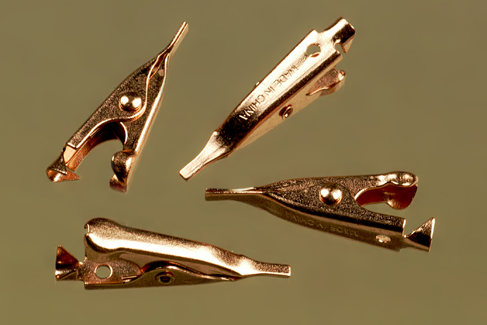
Figure 3-20. These small copper clips absorb heat to protect components when you’re soldering them.
Optional: Perforated Board
When you’re ready to move your circuit from a breadboard to a more permanent location, you’ll want to solder it to a piece of perforated board, often known as “prototyping board” and also called “perf board.”
The easiest type to use is plated with copper strips on the back in exactly the same layout as the conductors hidden inside a breadboard. This enables you to minimize errors by keeping the same layout of your components when they migrate to the perforated board. See Figure 3-21. Just buy one board, initially.
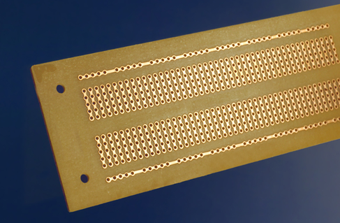
Figure 3-21. This perforated board has a pattern of copper traces identical to the pattern of conductors inside a breadboard.
The disadvantage of using the breadboard component layout is that it is not very space-efficient. To compress a circuit to minimal size, you can try point-to-point wiring on a plain perforated board—and I’ll show you how this is done in Experiment 14. You may only require a small piece of board, but you can buy a larger piece and cut as much as you need. See Figure 3-22.
Another possibility is to use perforated board with a different pattern of copper traces. Cut-board, for instance, features parallel traces that you can cut with a knife where you want to break a connection. Everyone who does much soldering seems to have a favorite type of board configuration, but I think you’ll need to get acquainted with the soldering process before you start exploring the options.
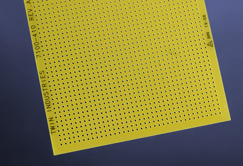
Figure 3-22. Plain perforated board (with no copper traces) for point-to-point wiring.
Optional: Plywood
When you use a soldering iron, hot drops of solder tend to fall onto your table or workbench. The solder solidifies almost instantly, can be difficult to remove, and will leave a scar. Consider using a two-foot square of half-inch plywood to provide disposable protection. You can buy it precut at any big-box hardware store.
Optional: Machine Screws
To mount components behind a panel, you need small machine screws (more commonly referred to as “bolts”). They look nice if they have flat heads that fit flush against the panel, provided you coutersink the holes. I suggest stainless-steel machine screws, #4 size, in lengths of 3/8” and 1/2”, with #4 locknuts of the type that have nylon inserts, so that they won’t work loose.
Essential: Project Boxes
A project box is just a small box (usually plastic) with a removable lid. As its name implies, its purpose is to hold one of your electronic projects. You mount your switches, potentiometers, and LEDs in holes that you drill in the lid, and you attach your circuit on a perforated board that goes inside the box. You can also use a project box to contain a small loudspeaker.
For the intrusion alarm project in Experiment 15, you can use a box measuring approximately 6 inches long, 3 inches wide, and 2 inches high.
Essential: Power Connectors
After you finish a project and put it in a box, you’ll need a convenient way to supply it with power. You can buy the kind of low-voltage DC plug-and-socket pair pictured in Figure 3-23. They are properly known as “barrel plugs” and “barrel sockets” but you may also find them described as “6VDC plug” and “6VDC socket.” They are available in various sizes, but this is unimportant, so long as your connectors are the same size as each other.
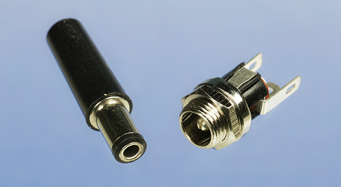
Figure 3-23. The socket on the right can be mounted on a project box to receive power from the plug on the left, which you can attach to the wire from an AC adapter.
Optional: Headers
After you have soldered a circuit to perforated board, you will need to connect it with separate switches or pushbuttons. An unpluggable connection is preferable, in case you ever need to fix a fault on the board.
Sometimes known as single inline sockets and headers, but also known as boardmount sockets and pinstrip headers, small connectors come in strips of 36 or more, and you can snap off as many as you need.
Figure 3-24 shows headers before and after being snapped into small sections. Make sure that the interconnects have a terminal spacing of 0.1 inch, to match your perforated board. (Some interconnects have metric spacing.)
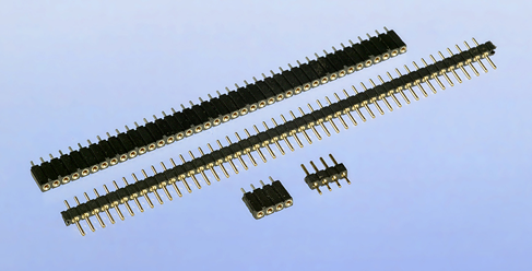
Figure 3-24. Miniature interconnects are often referred to as “headers.”
Components
Again I must remind you that component kits are available. See “Kits”. If you prefer to buy your own components from online sources, see “Components”. In addition to the components that I described at the beginning of Chapter Two (see “Components”), you’re going to need the following.
Diodes
A diode passes electric current in one direction, while blocking it in the opposite direction. The end of the diode that should be more negative is known as the cathode. It is marked with a line, as shown in Figure 3-25. The diode on the right, in this photograph, is a 1N4001, which is rated for slightly more current than the 1N4148 on the left. They’re cheap, and likely to be useful in the future, so buy 10 of each. The manufacturer is irrelevant.
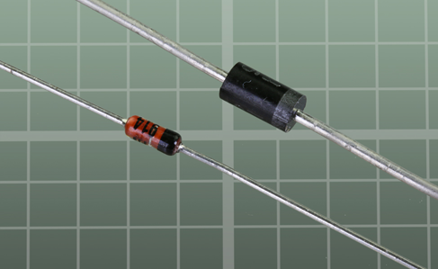
Figure 3-25. Two diodes. The more-negative end is marked.
Experiment 12: Joining Two Wires Together
Now you’re ready to begin using everything that I have just described, and the first item has to be a soldering iron.
Your adventure into soldering begins with the prosaic task of joining one wire to another, but will lead quickly to creating a full electronic circuit on perforated board. So let’s get started!
What You Will Need
-
Hookup wire, wire cutters, wire strippers
-
30-watt or 40-watt soldering iron
-
15-watt soldering iron
-
Thin solder
-
Optional: medium solder
-
“Helping Hand” to hold your work
-
Optional: shrink-wrap tubing, assorted
-
Optional: heat gun
-
Optional: a piece of heavy cardboard or plywood to protect your work area from drops of solder
Caution: Soldering Irons Do Get Hot!
Please take these basic precautions:
Use a proper stand (such as the one incorporated in a Helping Hand) to hold your soldering iron. Don’t leave the iron lying on a workbench.
If you have infants or pets, remember that they may play with, grab, or snag the wire to your soldering iron. They could injure themselves (or you).
Be careful never to rest the hot tip of the iron on the power cord that supplies electricity to the iron. It can melt the plastic in seconds and cause a dramatic short circuit.
If you drop a soldering iron, don’t be a hero and try to catch it.
Most soldering irons have no warning lights to tell you that they’re plugged in. As a general rule, always assume that a soldering iron is hot, even if it’s unplugged. It may retain sufficient heat to burn you for longer than you expect.
Your First Solder Joint
We’ll start with your general-duty soldering iron—the one rated for 30 or 40 watts. Plug it in, leave it safely in its holder, and find something else to do for five minutes. If you try to use a soldering iron without giving it time to get fully hot, you will not make good joints, because the solder may not melt completely.
Strip the insulation from the ends of two pieces of 22-gauge solid hookup wire and clamp them in your Helping Hand so that they cross each other and touch each other, as shown in Figure 3-26.

Figure 3-26. Ready for your first soldering adventure.
To make sure that the iron is ready, touch a thin piece of solder on the tip of it. The solder should melt instantly. If it melts slowly, the iron isn’t hot enough yet.
If the tip of your soldering iron is dirty, you should clean it. The usual procedure is to wet the sponge that is built into your soldering iron stand, and rub the tip of the iron in the sponge. Personally I prefer not to do this, as I believe that getting moisture on the tip causes thermal expansion and contraction, which may open small cracks in the plating of the tip. I rub a piece of crumpled paper over the hot tip of the soldering iron, quickly enough to avoid charring the paper. Then I apply a tiny amount of solder and rub the tip again, until it is uniformly shiny.
When the tip of your soldering iron is clean. follow the steps shown in Figure 3-27, Figure 3-28, Figure 3-29, Figure 3-30, and Figure 3-31.
Step 1. Touch the hot tip of the iron against the intersection of the wires steadily for three seconds to heat them.
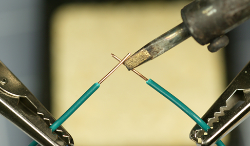
Figure 3-27. Step 1.
Step 2. While maintaining the iron in this position, feed a little solder to the intersection of the wires, also touching the tip of the soldering iron. Thus, the two wires, the solder, and the tip of the iron should all come together at one point.
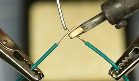
Figure 3-28. Step 2.
Step 3. At first, the solder may melt slowly. Be patient.

Figure 3-29. Step 3.
Step 4. Now you see the solder forming a nice round blob.
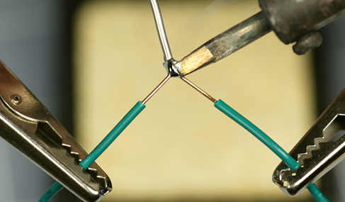
Figure 3-30. Step 4.
Step 5. Remove the iron and the solder. Blow on the joint to cool it. Within 10 seconds, it should be cool enough to touch. The completed joint should be shiny, uniform, and rounded in shape
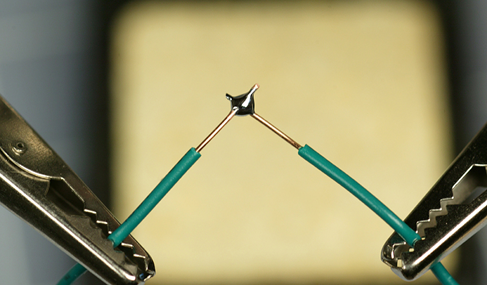
Figure 3-31. Step 5.
When the joint has cooled, unclamp the wires and try to tug them apart. Tug hard! If they defeat your best attempts to separate them, the wires are electrically joined and should stay joined. If you didn’t make a good joint, you will be able to separate the wires relatively easily, probably because you didn’t apply enough heat or enough solder. Figure 3-32 gives you the general idea.
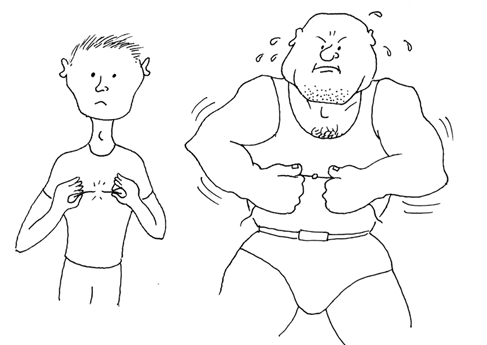
Figure 3-32. Telling the difference between a bad solder joint (left) and a good one (right) is really not very difficult.
The reason I asked you to begin by using the higher-powered soldering iron is that it delivers more heat, which makes it easier to use.
The soldering steps can be summarized like this: apply heat to the wires, bring in the solder while maintaining the heat, wait for the solder to start to melt, wait a moment longer for it to form a completely molten bead, and then remove the heat. The whole process should take between four and six seconds.
Background: Soldering Myths
Myth #1: Soldering is very difficult. Millions of people have learned how to do it, and they can’t all be more competent than you. I have a lifelong problem with a tremor in my hands that makes it difficult for me to hold small things steadily. I also get impatient with repetitive detail work. If I can solder components, almost anyone should be able to do it.
Myth #2: Soldering endangers your health with poisonous chemicals. You should avoid inhaling the fumes, but that also applies to everyday products such as bleach and paint. You should wash your hands after handling solder, and to do a really thorough job, use a nail brush. But if soldering was a significant health hazard, we should have seen a high death rate among electronics hobbyists decades ago.
Myth #3: Soldering irons are dangerous. A soldering iron is less hazardous than the kind of iron that you might use to iron a shirt, because it delivers less heat. In fact, in my experience, soldering is safer than most activities in a typical home or basement workshop. Of course, that doesn’t mean you can be careless. The iron is hot enough to burn your skin if you touch it.
Fundamentals: Eight Soldering Errors
Not enough heat. The joint looks OK, but because you didn’t apply quite enough heat, the solder didn’t melt sufficiently to realign its internal molecular structure. It remained granular instead of becoming a solid, uniform blob, and you end up with a dry joint, also known as a cold joint, which will come apart when you pull the wires away from each other. Reheat the joint thoroughly and apply new solder.
Carrying solder to the joint. A leading cause of underheated solder is the temptation to melt some solder onto the iron alone, and then carry the solder to the location where you want to apply it. This means that the wires will be cold when you try to make the solder stick to them. What you should do is touch the soldering iron to heat the wires first, and then apply the solder. This way, the wires are hot and help to melt the solder.
-
Because this is such a universal problem, I’ll repeat myself. You don’t want to put hot solder on cold wires. You want to put cold solder on hot wires.
Too much heat. This may not hurt the joint, but can damage everything around it. Vinyl insulation will melt, exposing too much wire and raising the risk of short circuits. You can easily damage semiconductors, and may even melt the internal plastic parts of switches and connectors. Damaged components must be desoldered and replaced, which will take time and is a big hassle. If your attempt at soldering isn’t working for some reason, pull back, pause, and allow everything to cool down a little before you try again.
Not enough solder. A thin connection between two conductors may not be strong enough. When joining two wires, always check the underside of the joint to see whether the solder penetrated completely.
Moving the joint before the solder solidifies. This may create a fracture that you won’t necessarily see. It may not stop your circuit from working, but at some point in the future, as a result of vibration or thermal stresses, the fracture can separate just enough to break electrical contact. Tracking it down will then be a chore. If you clamp components before you join them, or use perforated board to hold the components steady, you can avoid this problem.
Dirt or grease. Electrical solder contains rosin that cleans the metal that you’re working with, but contaminants can still prevent solder from sticking. If any component looks dirty, clean it with fine sandpaper before joining it.
Carbon on the tip of your soldering iron. The iron gradually accumulates flecks of black carbon during use, and they can act as a barrier to heat transfer. Clean the tip, as described previously.
Inappropriate materials. Electrical solder is designed for electronic components. It will not work with aluminum, stainless steel, or various other metals. You may be able to make it stick to chrome-plated items, but only with difficulty.
Failure to test the joint. Don’t just assume that it’s OK. Always test it by applying manual force. If you can’t get a grip on the joint, slip a screwdriver blade under it and flex it just a little, or use small pliers to try to pull it apart. Don’t be concerned about ruining your work. If your joint doesn’t survive rough treatment, it wasn’t a good joint.
Of the eight errors, dry/cold joints are by far the worst, because they are easy to make and can look OK.
Background: Soldering Alternatives
As recently as the 1950s, connections inside electronic appliances such as radio sets were still being hand-soldered by workers on production lines. But the growth of telephone exchanges created a need for a faster way to make large numbers of rapid, reliable point-to-point wiring connections, and wire wrap became a viable alternative.
In a wire-wrapped electronics project, components are mounted on a circuit board that has long, gold-plated, sharp-cornered square pins sticking out of the rear. Special silver-plated wire is used, with an inch of insulation stripped from its ends. A manual or power-driven wire-wrap tool twirls the end of a wire around one of the pins, applying sufficient tension to “cold-weld” the soft silver plating of the wire to the pin. The wrapping process exerts sufficient pressure to make a very reliable joint, especially as seven to nine turns of wire are applied, each turn touching all four corners of the pin.
During the 1970s and 1980s, this system was adopted by hobbyists who built their own home computers. A wirewrapped circuit board from a hand-built computer is shown in Figure 3-33. The technique was used by NASA to wire the computer in the Apollo spacecraft that went to the Moon, but today, wire-wrapping has few commercial applications.
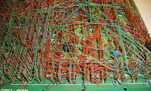
Figure 3-33. This picture shows some of the wire-wrapping in Steve Chamberlin’s custom-built, retro 8-bit CPU and computer. Connecting such a network of wires with hand soldering would have been unduly time-consuming and prone to faults. Photo credit: Steve Chamberlin.
The widespread industrial use of “through-hole” components, such as the chips on early desktop computers, encouraged development of wave soldering, in which a wave or waterfall of molten solder is applied mechanically to the underside of a preheated circuit board where chips have been inserted. A masking technique prevents the solder from sticking where it isn’t wanted.
Today, surface-mount components (which are significantly smaller than their through-hole counterparts) are glued to a circuit board with a solder paste, and the entire assembly is then heated, melting the paste to create a permanent connection.
Your Second Solder Joint
Time now to try your 15W soldering iron. Once again, you must leave it plugged in for a good five minutes to make sure it’s hot enough. In the meantime, don’t forget to unplug your other soldering iron, and put it somewhere safe while it cools.
Use thin solder to make this joint. It will take less heat from the less-powerful soldering iron.
This time I’d like you to align the wires parallel with each other. Joining them this way is a little more difficult than joining them when they cross each other, but it’s a necessary skill. Otherwise, you won’t be able to slide heat-shrink tubing over the finished joint to insulate it.
Five steps to create this joint are shown in Figure 3-34, Figure 3-35, Figure 3-36, Figure 3-37, and Figure 3-38. At the beginning, the two wires do not have to make perfect contact with each other; the solder will fill any small gaps. But as before, the wires must be hot enough for the solder to flow, and this can take an extra few seconds when you use the low-wattage iron.
Be sure to feed the solder in as shown in the pictures. Remember: don’t try to carry the solder to the joint on the tip of the iron. Heat the wires first, and then touch the solder to the wires and the tip of the iron, while keeping it in contact with the wires. Wait until the solder liquifies, and you will see it running eagerly into the joint. If this doesn’t happen, be more patient and apply the heat for a little longer.
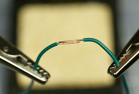
Figure 3-34. Step 1: Align the wires.
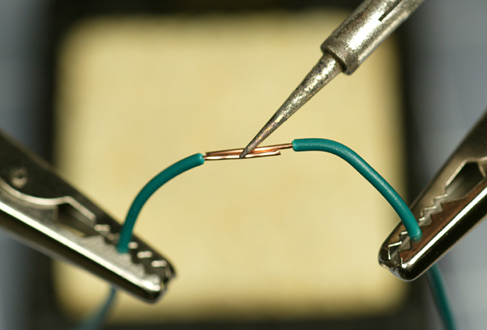
Figure 3-35. Step 2: Heat the wires.
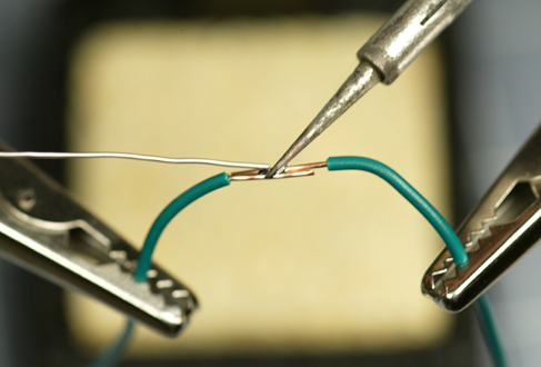
Figure 3-36. Step 3: While continuing to heat the wires, apply the solder. Wait for it to start melting. Be patient.
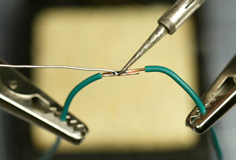
Figure 3-37. The solder is now melting into the joint.
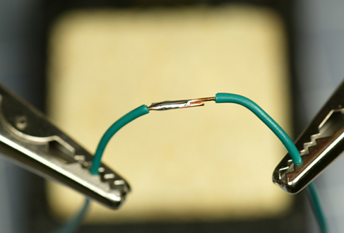
Figure 3-38. The finished joint is shiny, and the solder has spread across the copper wires.
The finished joint has enough solder for strength, but not so much solder that it will prevent heat-shrink tubing from sliding over it. I’ll get to that in a moment.
Theory: Heat Transfer
The better you understand the process of soldering, the easier it should be for you to make good solder joints.
The tip of the soldering iron is hot, and you want to transfer that heat into the joint that you are trying to make. For this reason, you should adjust the angle of the soldering iron so that it makes the widest possible contact. See Figure 3-39 and Figure 3-40.
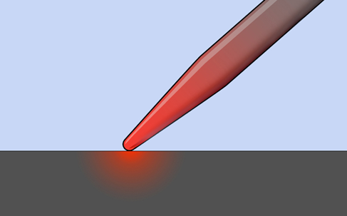
Figure 3-39. A small contact area between the iron and the working surface allows insufficient heat transfer.
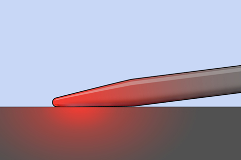
Figure 3-40. A larger area of contact increases the heat transfer.
Once the solder starts to melt, it broadens the area of contact, which helps to transfer more heat, so the process accelerates naturally. Initiating it is the tricky part.
The other aspect of heat flow that you should consider is that it can suck heat away from the places where you want it, and deliver it to places where you don’t want it. If you’re trying to solder a very heavy piece of copper wire, the joint may never get hot enough to melt the solder, because the heavy wire conducts heat away from the joint. You may find that even a 40-watt iron isn’t powerful enough to overcome this problem. At the same time, while the copper doesn’t get hot enough to melt the solder, it can be quite hot enough to melt insulation off the wire.
As a general rule, if you can’t complete a solder joint in 10 seconds, you aren’t applying enough heat.
Insulating the Solder Joint
After you’ve succeeded in making a good inline solder connection between two wires, it’s time for the easy part. Choose some heat-shrink tubing that is just big enough to slide over the joint with a little bit of room to spare.
Of course, you do need to plan ahead. Usually you need to slip some tubing over one of the wires before you join them together. You’ll see how this works when I get to the step-by-step procedure, below.
Assuming you have heat-shrink tubing on one of the wires, slide it along until the joint is centered under it. Hold it in front of your heat gun, and switch on the gun (keeping your fingers away from the blast of superheated air). Turn the wire so that you heat both sides. The tubing should shrink tight around the joint within half a minute. If you overheat the tubing, it may shrink so much that it splits, at which point you must remove it and start over. As soon as the tubing is tight, your job is done, and there’s no point in making it any hotter. Note that while tubing mostly shrinks at right angles to its length, a little shrinkage also occurs along its length.
Figure 3-41, Figure 3-42, and Figure 3-43 show the desired result. I used white tubing because it shows up well in photographs. Different colors of heat-shrink tubing all perform the same way.
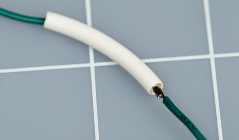
Figure 3-41. Slip the tubing over your wire joint.
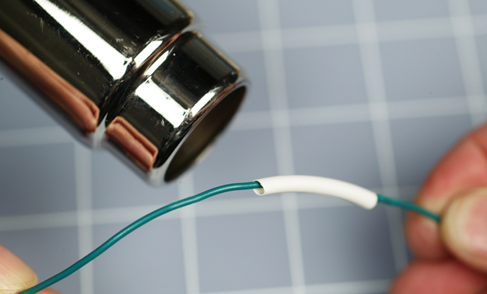
Figure 3-42. Apply heat to the tubing.

Figure 3-43. Leave the heat on the tubing until it shrinks to firmly cover the joint.
Caution: Heat Guns Do Get Hot!
Notice the chromed steel tube at the business end of a full-sized heat gun. Steel costs more than plastic, so the manufacturer must have put it there for a good reason—and the reason is that the air flowing through it becomes so hot that it would melt a plastic tube.
The metal tube stays hot enough to burn you for several minutes after you’ve used it. And, as in the case of soldering irons, other people (and pets) are vulnerable, because they won’t necessarily know that the heat gun is a hazard. Most of all, make sure that no one in your home ever makes the mistake of using a heat gun as a hair dryer (see Figure 3-44).

Figure 3-44. Members of your family should understand that a heat gun isn’t quite the same as a hair dryer.
This tool is just a little more hazardous than it appears. A mini heat gun may entail slightly less risk, but still should be treated with respect.
Wiring Your Power Source
The next application for your soldering skills will be more practical. You can add color-coded, solid-core wires to your AC adapter—or if you don’t have an adapter, you can add extensions to the thin wires from a 9V battery connector. Either way, your extended 22-gauge wires will plug conveniently into a breadboard.
You can use your larger soldering iron for this, as no heat-sensitive components are involved.
If you have acquired an AC adapter, I’m assuming it is a little plastic module that plugs straight into the wall. A pair of wires emerges from it, carrying the low DC voltage that you need, and they terminate in some kind of miniature plug. The plug is suitable for a device such as a media player or a phone that has a matching socket, but for the purposes of this book, the plug is not useful, because you will want to apply the power to a breadboard.
How can this be done? I will show you.
Step One: Cut and Measure
First, let’s make sure your AC adapter is doing what it’s supposed to do.
Do not plug the adapter into the wall just yet. Begin by cutting the little plug off the end of the low-voltage wire, as shown in Figure 3-45. (You may notice that this photograph is of a RadioShack adapter. Ah, memories.)
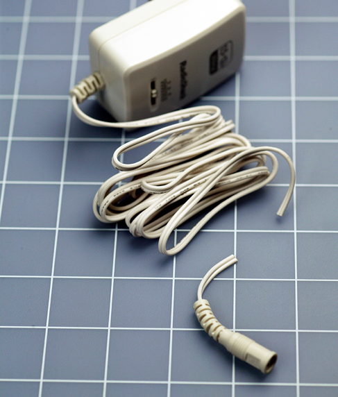
Figure 3-45. The first step in customizing an AC adapter.
Separate the two conductors, using wire cutters or a utility knife, and strip about 1/4” of insulation off each one. See Figure 3-46. The wires should be of unequal lengths, to reduce the risk of them touching.
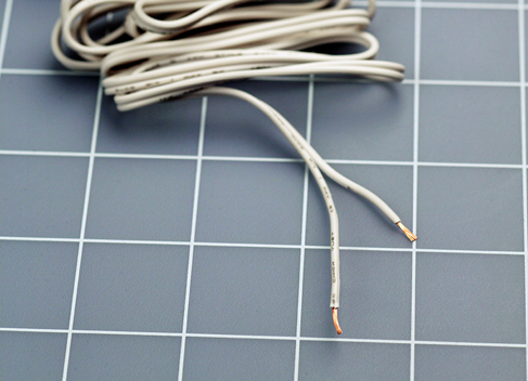
Figure 3-46. The stripped wires.
If the bare ends do touch each other while the adapter is plugged in, they may overload it or blow a fuse inside it. You may also get a spark that will be disconcerting, although I doubt it will hurt you. Not a big deal, but inconvenient.
Now set your meter to measure volts DC and attach it to the two wires from the AC adapter, preferably using alligator test leads to keep everything under control. After double-checking to make sure that your red meter lead is in the volts socket on the meter, not the mA socket, plug the AC adapter into the wall and measure how much voltage it is providing.
If you get a confusingly high reading, it could be because the voltage delivered by AC adapters is often greater when the adapter is not powering anything. The internal resistance of your meter is so high, the adapter will behave as if it isn’t being loaded at all.
For a more meaningful test, select a resistor with a value of 680 ohms and clip it across the output from the adapter, in parallel with your meter. This will pull the voltage from the adapter down to a more appropriate level. Now you should get a value that makes sense.
It’s not a good idea to use a resistor of much less than 680 ohms because the resistors on your shopping list are only rated at 1/4 watt, and if you try to push more power through them than that, they will overheat. If the 680-ohm resistor is attached to a 9-volt supply, Ohm’s Law tells us that the current flowing through it will be about 13mA, and therefore the power dissipation will be about 120mW, or 0.12W, which is well within the rated maximum of a 0.25W resistor.
If you want to see how the voltage output from your AC adapter varies with a load of lower resistance, you can clip several 680-ohm resistors together in parallel. This could be an interesting test—but let’s get back to the primary purpose here, which is to obtain power for your breadboard.
Step Two: Soldering
Use your meter to make absolutely sure there is no minus sign in front of the voltage that it measures on the wires from your AC adapter. If there is a minus sign, reverse the leads from your meter.
If the reading on your meter is positive, not negative, you know that the red wire from your meter is clipped to the positive side of your AC adapter. This is important, as you don’t want your adapter to destroy components in your circuits by applying power to them the wrong way around.
The next steps will be the same regardless of whether you are adding solid 22-gauge wires to an AC adapter or a 9V battery connector.
Cut two pieces of solid-conductor 22-gauge wire—one of them red, the other black or blue. Each should be about 2 inches long. Strip 1/4” of insulation from both ends of each piece of wire.
Solder the 22-gauge wires to the wires from the AC adapter or the battery connector, using the technique that you practiced previously. Naturally, you attach the red wire to the positive side of your power supply.
If you have heat-shrink tubing and a heat gun, use it as you did in the practice session. The result should look like Figure 3-47. Once again the wires should be of unequal lengths, to reduce the risk of them touching each other. When the job is done, you can plug the ends of the 22-gauge wires into your breadboard.
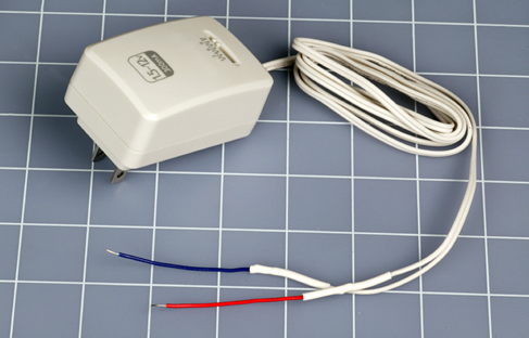
Figure 3-47. The 22-gauge wires can be plugged into a breadboard, to supply it with power.
Pruning a Power Cord
What else can you do with your newly acquired soldering skills? Here’s a suggestion. Those of us who don’t use Apple products may find ourselves with a laptop power supply that has a detachable AC power cord for plugging into the wall, in addition to the low-voltage DC wire that plugs into the computer. A typical power cord is shown in Figure 3-48.
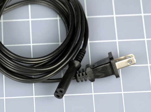
Figure 3-48. A detachable AC power cord for a non-Apple laptop computer.
What if you are an Apple fan? Maybe you have detachable power cords for other devices, such as a printer or a scanner. The purpose of this exercise is to reduce the length of a power cord so that it is exactly what you want, instead of lying around in a tangle. And if, like me, you have a laptop power cord that is longer than it needs to be, and you like to travel as light as possible, this exercise could be useful.
Twelve Steps to a Shorter Cord
In Figure 3-49 we see the first step, in which you boldly apply your wire cutters to chop a power cord. Needless to say, all of these steps require that the power cord should not be plugged in while you are working on it.
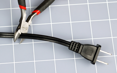
Figure 3-49. Step 1 of 12, to shorten a power cord.
Figure 3-50 shows the ends that you want to keep. You can store the rejected middle section of the power cord for some other purpose in the future.
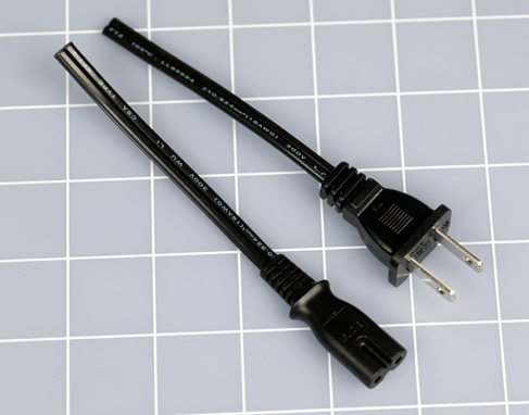
Figure 3-50. Step 2 of 12, to shorten a power cord.
In Figure 3-51, a utility knife on a cutting mat is an easy way to separate the two conductors in each segment of the power cord.
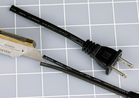
Figure 3-51. Step 3 of 12, to shorten a power cord.
In Figure 3-52, the segments of the power cord have been trimmed so that the conductors are of matching but unequal lengths. This way they will take up less room when you rejoin them, and there will be less risk of a short circuit if one of the joints fails for some reason.
Note that one conductor will be always marked, either with print or with molded ridges. Be sure that the marked conductors match each other when you join them.
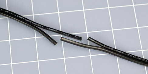
Figure 3-52. Step 4 of 12, to shorten a power cord.
Strip off a minimal amount of insulation. Just 1/8” (3mm) will be enough. Then cut some pieces of heat-shrink tubing, if you have it. Each smaller piece must be just large enough to slide over each individual conductor in the power cord, while the bigger piece, about 2” long, will cover the whole joint. See Figure 3-53.
Note that some heat-shrink tubing is rated only for low voltages. It should not be used for this project.
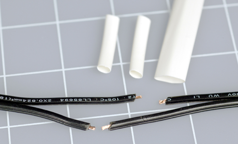
Figure 3-53. Step 5 of 12, to shorten a power cord.
Now for the most difficult part: activating your human memory. You have to remember to slide the tubing onto the wire before you make your solder joint, because the plugs on the ends of the wires will prevent you from adding any heat-shrink tubing later. If you’re as impatient as I am, it’s very difficult to remember to do this every time. See Figure 3-54.
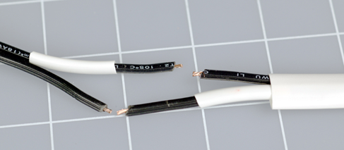
Figure 3-54. Step 6 of 12, to shorten a power cord.
Use your Helping Hand to align the first joint. Push the two pieces of wire together so that the strands intermingle, and then squeeze them tight between finger and thumb, so that there are no little bits sticking out. A stray strand of wire can puncture heat-shrink tubing when the tubing is hot and soft and is shrinking around the joint. See Figure 3-55.
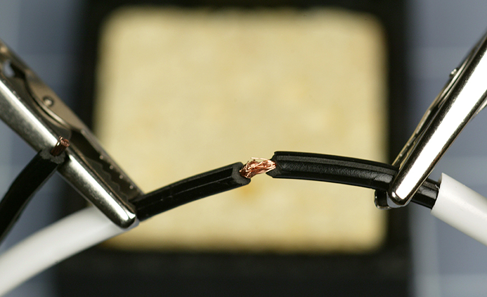
Figure 3-55. Step 7 of 12, to shorten a power cord.
The wire that you’re joining is much heavier than the 22-gauge wire that you worked with previously, so it will suck up more heat, and you must touch the soldering iron to it for a longer time. Make sure that the solder flows all the way into the joint, and check the underside after the joint is cool. Most likely you’ll find some bare copper strands there. The joint should become a nice solid, rounded, shiny blob. See Figure 3-56.
Be careful to keep the heat-shrink tubing as far away from the joint as possible while you’re using the soldering iron, so that heat from the iron doesn’t shrink the tubing prematurely, preventing you from sliding it over the joint later.
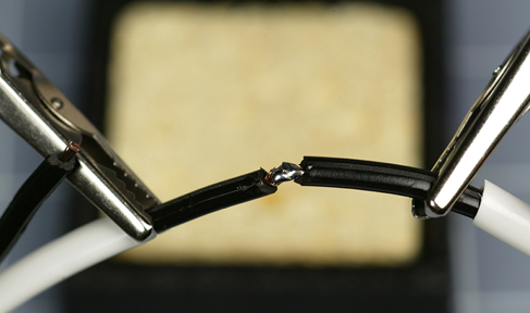
Figure 3-56. Step 8 of 12, to shorten a power cord.
Slide a section of heat-shrink tubing over the solder joint, and apply the heat gun, as shown in Figure 3-57. Don’t allow the other pieces of heat-shrink tubing to pick up stray heat.

Figure 3-57. Step 9 of 12, to shorten a power cord.
In Figure 3-58, the heat-shrink tubing has now shrunk.
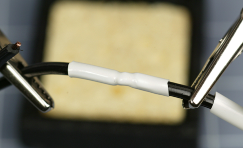
Figure 3-58. Step 10 of 12, to shorten a power cord.
Get ready to solder the other pair of conductors. See Figure 3-59.
Figure 3-60 shows that the second joint has been made. After you protect it with its own piece of heat-shrink tubing, you’ll be ready to slide the larger section of tubing over the whole assembly. Er—you did remember to put the large tubing onto the wire at the beginning, didn’t you?
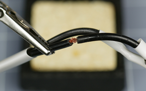
Figure 3-59. Step 11 of 12, to shorten a power cord.
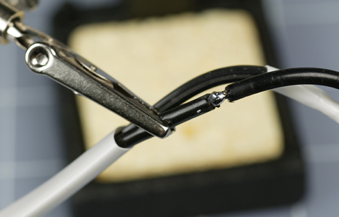
Figure 3-60. Step 12 of 12, to shorten a power cord.
Figure 3-60 shows the finished shortened power cord.
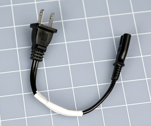
Figure 3-61. The power cord, shortened.
What’s Next?
If you have completed the soldering exercises so far, you have sufficient basic skills to build your first soldered electronic circuit. Although—maybe first we should just run through a quick demonstration of the consequences of unintentionally excessive heat. I’d hate for you to take a lot of trouble soldering things together, only to discover that you melted a transistor or an LED. Unsoldering damaged parts is much less fun than soldering them.
Experiment 13: Roasting an LED
In Experiment 4, you discovered how easy it is to burn out an LED. What really happened, in that little adventure, is that excessive current passing through the LED created excessive heat, and the heat killed the component.
If heat caused by electricity can destroy an LED, do you think heat from a soldering iron can do the same thing? It sounds plausible, but there’s only one way to make absolutely sure.
What You Will Need
-
9V battery and connector, or 9V AC-DC adapter
-
Long-nosed or sharp-nosed pliers
-
30-watt or 40-watt soldering iron
-
15-watt soldering iron
-
LEDs, generic (2)
-
470-ohm resistor (1)
-
Helping Hand to hold your work
-
One large or two small pure-copper alligator clips
The purpose of the experiment is to study the effects of heat. This means we need to know where the heat is going.
For this reason, you’re not going to use a breadboard. The contacts inside the board would absorb an unknown amount of heat. I don’t want you to use test leads, either, because they too will absorb heat.
Instead, please use some sharp-nosed pliers to bend each of the leads from an LED into little hooks, and do the same thing with the wires on a 470-ohm resistor. See Figure 3-62, where you will see that the wires from a 9-volt battery have been bent the same way. To make them maintain the hook shape, you may need to strip off a little extra insulation and apply a little solder.
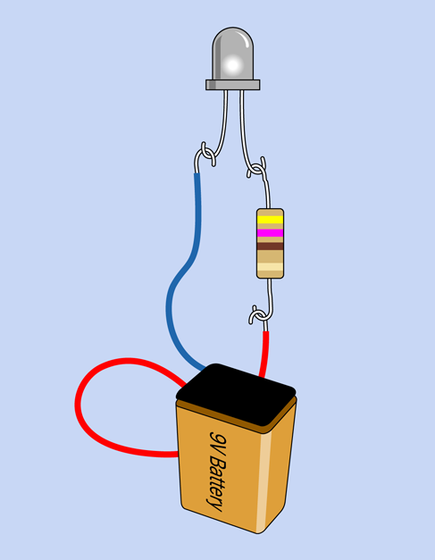
Figure 3-62. Measuring the heat tolerance of an LED. An AC adapter can substitute for the 9-volt battery.
To minimize heat loss through conduction, the resistor dangles from one of the leads on the LED, and the power-supply wire hangs from that, a little farther down. Gravity should be sufficient to make this work.
Grip the plastic body of the LED in your Helping Hand. Plastic is not a good thermal conductor, so the lens of the LED should not allow much heat to be conducted away through the Helping Hand.
Apply the 9 volts, and your LED should be shining brightly. I used a white LED in this experiment, because it’s easier to photograph.
You’ll need your low-powered 15W soldering iron, and the higher-powered one, too. Plug them in and wait at least five minutes, to make sure they are really hot. Now hold the tip of the 15W iron firmly against one of the leads on your glowing LED, while you check the time with a watch. Figure 3-63 shows the setup.
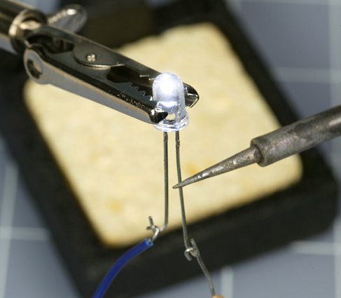
Figure 3-63. Applying heat with a 15-watt soldering iron.
I’m betting that you can sustain this contact for a full three minutes without burning out the LED. Now you know why a 15-watt soldering iron is recommended for delicate electronics work.
Allow your LED wire to cool, and then apply your more powerful soldering iron in the same location as before. I think you’ll find that the LED will go dark after as little as 10 seconds (note that some LEDs can survive higher temperatures than others). This is why you don’t use a 30-watt soldering iron for delicate electronics work.
The large iron doesn’t necessarily reach a higher temperature than the small one. It just has a larger heat capacity. In other words, a greater quantity of heat can flow out of it, at a faster rate.
Your LED has been sacrificed to satisfy the need for knowledge. It was an honorable death. Lay it to rest in your trash, and substitute a new LED, which we will try to treat more kindly. Connect it as before, but this time add a full-size copper alligator clip (or two small clips) to one of the leads near the body of the LED, as shown in Figure 3-64. Press the tip of your 30-watt or 40-watt soldering iron against the lead just below the alligator clip. This time, you should be able to hold the powerful soldering iron in place for a full two minutes without burning out the LED.

Figure 3-64. Using a copper alligator clip as a heat sink to protect an LED.
Where the Heat Goes
At the end of your experiment, if you touch the clip, you’ll find that it’s relatively hot, while the LED remains not so hot. Imagine the heat flowing out through the tip of your soldering iron, into the wire that leads to the LED—except that the heat meets the alligator clip along the way, as shown in Figure 3-65. The clip is like an empty container waiting to be filled. The heat prefers to flow into the copper clip, leaving the LED unharmed.
The alligator clip functioned as a heat sink. It works better than an everyday nickel-plated steel alligator clip, because copper is such a good conductor of heat.
Going back to the first part of this experiment, you saw that a 15-watt soldering iron failed to harm the LED, with no heat sink needed. Does this mean that a 15-watt iron is completely safe?
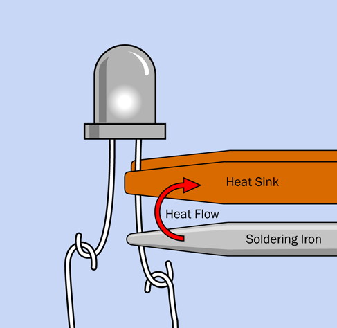
Figure 3-65. A copper alligator clip conducts heat away from an LED.
Well, maybe. The problem is, you don’t really know whether some semiconductors may be more heat-sensitive than LEDs.
Because the consequences of burning out a component can be so annoying, I suggest you should consider playing it safe and use a heat sink in these circumstances:
-
If you apply a 15-watt iron extremely close to a semiconductor for 20 seconds or more.
-
If you apply a 30-watt iron within half an inch of resistors or capacitors for 10 seconds or more. (Never use it near semiconductors.)
-
If you apply a 30-watt iron near anything meltable for 20 seconds or more. Meltable items include insulation on wires, plastic connectors, and plastic components inside switches.
Rules for Heat Sinking
-
Full-size copper alligator clips work best, but may not fit into tight corners. Ideally you should have small ones available too.
-
Clamp the alligator clip as close as possible to the component and as far as possible from the solder joint that you are trying to make. The joint does need to get hot. Divert heat from the component, not from the joint.
-
Make sure there is a metal-to-metal connection between the alligator clip and the wire to promote good heat transfer.
If you keep these points in mind, we can proceed with the fascinating challenge of point-to-point wiring.
Experiment 14: A Wearable Pulsing Glow
Until now, I’ve encouraged you to start putting things together without much of a theory or a plan. That’s what Learning by Discovery tends to be like. Sometimes, though, a plan can be essential, and this is one of those times. I’m going to outline the requirements of this project, and then I will take you step by step through the process of building it.
What You Will Need
-
9V battery and connector, or 9V AC-DC adapter
-
Hookup wire, wire cutters, wire strippers, multimeter
-
15-watt soldering iron
-
Thin solder (0.022 inches)
-
Plain perforated board (no copper plating necessary)
-
Helping Hand
-
Resistors: 470 (2), 100K (1), 4.7K (2), 470K (2)
-
Capacitors: 3.3µF (2), 220µF (1)
-
Transistors: 2N2222 (3)
-
Generic LED (1)
Fluctuations Revisited
Please turn back to Figure 2-116 to refresh your memory of that circuit. The task, now, is to make it as small as possible, so that someone could wear it.
Imagine that the leads of the components are interconnected with rubber bands, allowing you to shuffle them around on a tabletop without them losing their connections with each other. When the rubber bands are stretched as little as possible, the circuit is as small as possible, and you can link the parts with bare wires, supporting everything with a piece of perforated board.
The only problem is that bare wires under the board cannot cross each other. The idea is that after you have verified the function of your circuit, you could send the specification to a service that etches circuit boards.
Of course, modern printed circuits are double-sided, at the very least, and many have intermediate layers, allowing multiple conductors to cross each other without making electrical contact. But it’s always good to start on a simple, traditional basis, and the simplest board has components on one side and connections on the other. Components on top of the board can bridge the conductors beneath, because the insulating material of the board separates them. But conductors cannot cross each other.
My best attempt to reduce the size of this circuit is shown in Figure 3-66, on a piece of plain perforated board measuring 0.9” x 1.3”. If you can come up with a design that is significantly smaller, I’d love to see it. Here are some ideas:
-
Use smaller resistors rated for 1/8 watt instead of 1/4 watt.
-
Mount resistors vertically.
-
Thread two leads through one hole, if the holes in your board are big enough.
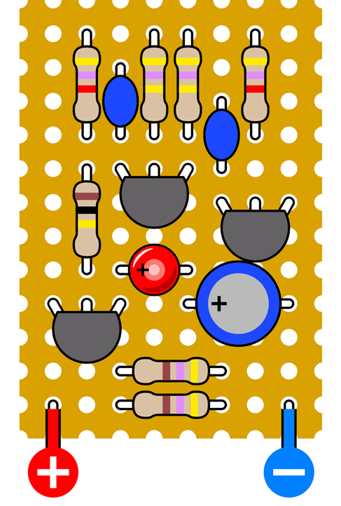
Figure 3-66. The oscillator circuit, reduced to occupy minimal space on perforated board.
Where are the connections between the components? They’re under the board. In Figure 3-67 I grayed out the components and disappeared the board, so that you can see the wiring.
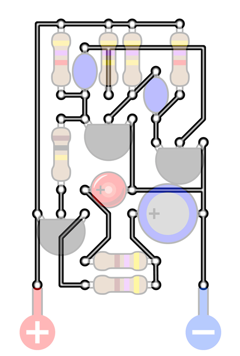
Figure 3-67. Connections in black are wires beneath the circuit board, which is transparent in this view.
If you compare this diagram very carefully with the schematic in Figure 2-116, you should find that the connections between components are the same—unless I made an error. (I sure hope not. I don’t want to have to redraw everything.)
Figure 3-68 shows yet another view, this time omitting the components while including the board, so that you can see how the connections fit the 0.1” x 0.1” grid of holes in the board.
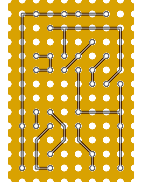
Figure 3-68. In this view, only the board and the connections are shown. Every circular dot indicates a connection that comes through a hole in the board.
Finally, Figure 3-69 shows the board flipped over, left to right, so that you are viewing it from behind. This will help you to make the connections when you’re putting the components together. You are going to give this a try, aren’t you?
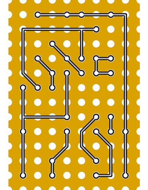
Figure 3-69. The previously shown connections are flipped left to right, so that this is the way the board should look from the underside.
Bend Wires, Add Solder
Now that you’ve seen the plan for this project, how are you supposed to make all those connections?
It’s not so difficult. Resistors, capacitors, and transistors have wire leads that are usually at least 1/2” long. So, you can push them through the holes in the perforated board, and then bend the leads over to touch each other. While they are touching, you solder them together. Snip off any surplus, add a battery connection, and you’re done.
There are three main issues to watch out for.
-
Holding the board steady while you work on it requires some care and patience. Your Helping Hand will be necessary.
-
The components and the solder joints that you make will be very close together. Use your copper alligator clips to provide heat protection.
-
Flipping between the top side of the board and the bottom side is confusing. You can easily put a wire in the wrong place. I think this is actually the hardest part.
Perhaps you have seen perforated board on which a little circle of copper has been added around each hole. Would that be suitable for this project? The copper circles have the advantage of anchoring components securely, but they can also create a short circuit between wires that are close together. I think bare board is easier for a small project like this. A sample was shown in Figure 3-22. Some perforated board has holes that are larger, but this does not make a significant difference.
Step by Step
Here’s the specific procedure for building the circuit:
Cut a piece of perfboard measuring 0.9” by 1.3” out of a plain sheet. (You don’t need a ruler calibrated in tenths of an inch. Just count the rows of holes in the board.) You can use a miniature hobby saw, or you may be able to snap the board along its lines of holes, if you’re careful. A hacksaw will also work. I suggest you should not use a good wood saw, because perforated board often has glass fibers in it, and they can blunt a saw.
Gather all the components and carefully insert three or four of them through holes in the board, counting the holes to make sure everything is in the right place. Flip the board over and bend the wires from the components to anchor them to the board and create the connections shown in Figure 3-69. If any of the wires isn’t long enough, you’ll have to supplement it with an extra piece of 22-gauge wire from your supply. Remove the insulation, which just gets in the way.
Trim the wires approximately with your wire cutters.
Make the joints with your soldering iron.
Now, the important part: check each joint using a close-up magnifying glass, and wiggle the wires with pointed-nosed pliers. If there isn’t enough solder for a really secure joint, reheat it and add more. If solder has created a connection that shouldn’t be there, use a utility knife to make two parallel cuts in the solder, and scrape away the little section between them.
Generally, I deal with just three or four components at a time, because I get confused if there are more than that. If I solder one component in the wrong location, undoing the error is not too difficult—unless I have already added more components to it by the time I discover the error.
Caution: Flying Wire Segments
The jaws of your wire cutters exert a powerful force that peaks and then is suddenly released when they cut through wire. This force can be translated into sudden motion of the snipped wire segment. Some wires are relatively soft, and don’t pose a risk, but transistors and LEDs tend to have harder wires. Little segments can fly in unpredictable directions at high speed, creating a real hazard for your eyes when you are doing close-up work.
Everyday eyeglasses can protect you when trimming wires. If you don’t use eyeglasses, plastic safety glasses are really a good idea.
Finishing the Job
I always use bright illumination. This is not a luxury; it is a necessity. Buy a desk lamp, if you don’t already have one. It doesn’t have to be expensive; a thrift-store item is okay.
I use a daylight-spectrum LED desk lamp, because it helps me to identify the colored bands on resistors more reliably. I stopped using a fluorescent desk lamp when I discovered that any small imperfection in the coating inside the tube can allow ultraviolet light to escape. This constitutes a hazard when you are working so close to the light.
No matter how good your vision is, you need to examine each joint with a magnifier. You’ll be surprised how imperfect some of them are. Hold the magnifier as close as possible to your eye, then pick up the board and bring it closer until the joint that you are inspecting comes into focus.
Finally, you should end up with a working circuit that pulses like a heartbeat. Or does it? If you have difficulty making it work, retrace every connection and compare it with the schematic. If you don’t find an error, apply power to the circuit, attach the black lead from your meter to the negative side, and then go around the circuit with the red lead, checking the presence of voltage. Every part of this circuit should show at least some voltage while it’s working. If you find a dead connection, you may have made a bad solder joint, or missed one entirely.
When you’re done, now what? Well, now you can stop being an electronics hobbyist and become a crafts hobbyist. You can try to figure out a way to make this thing wearable.
First you have to consider the power supply. Because of the components that I used, you really need 9 volts to make this work well. How are you going to make this 9-volt circuit wearable, with a bulky 9-volt battery?
I can think of three answers:
-
You can put the battery in a pocket, and mount the flasher on the outside of the pocket, with a thin wire penetrating the fabric.
-
You could mount the battery inside the crown of a baseball cap, with the flasher on the front.
-
You can put three 3-volt button batteries in a stack, held in some kind of plastic clip. I’m not sure how long they’ll last, though.
I have to note that the 2N2222 transistors in this project are not ideal, because they tend to use more power than field-effect transistors, also known as MOSFETS. However, I made a decision in this book that I only had space for one transistor family, and bipolar NPNs are the most fundamental type.
Regarding your choice of LED, those with a clear lens create a defined beam of light, which may not be appropriate for this project. Those that are diffused create a more pleasing glow. You can diffuse the light more by embedding the LED in a piece of transparent acrylic plastic, at least 1/4 inch thick, as shown in Figure 3-70. Roughen the front of the acrylic with fine sandpaper, ideally using an orbital sander that won’t make an obvious pattern. This will make the acrylic translucent rather than transparent.
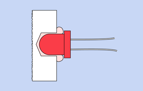
Figure 3-70. This cross-sectional view shows a sheet of transparent acrylic in which a hole has been drilled part of the way from the back toward the front. Because a drill bit creates a hole with a conical shape at the bottom, and because the LED has rounded contours, transparent epoxy or silicone caulking can be injected into the hole before mounting the LED.
Drill a hole slightly larger than the LED in the back of the acrylic. Don’t drill all the way through the plastic. Remove all fragments and dust from the hole by blasting some compressed air into it, or by washing it if you don’t have an air compressor. After the cavity is completely dry, get some transparent silicone caulking or mix some clear five-minute epoxy and put a drop in the bottom of the hole. Then insert the LED, pushing it in so that it forces the epoxy to ooze around it, making a tight seal.
Try illuminating the LED, and sand the acrylic some more if necessary. Finally, you can decide whether to mount the circuit on the back of the acrylic, or whether you want to run a wire to it elsewhere.
You can choose the resistors in the oscillator circuit to make the LED flash at about the speed of a human heart while the person is resting. This may make it look as if it’s measuring your pulse, especially if you mount it on the center of your chest or in a strap around your wrist. If you enjoy hoaxing people, you can suggest that you’re in such amazingly good shape, your pulse rate remains constant even when you’re taking strenuous exercise.
To make a good-looking enclosure for the circuit, I can think of options ranging from embedding the whole thing in clear epoxy to finding a Victorian-style locket. I’ll leave you to consider alternatives, because this is a book about electronics rather than craft projects. However, there is one craft-related issue that I want to mention, and this is a good moment to do so.
Background: Maddened by Measurement
Throughout this book, I’ve mostly used measurements in inches. Sometimes, though, I’ve ventured into the metric system, as when referring to “5mm LEDs.” This isn’t inconsistency on my part; it reflects the conflicted state of the electronics industry, where you’ll find inches and millimeters both in daily use, often in the very same datasheet. For instance, the pin spacing of surface-mount chips tends to be measured in millimeters, but through-hole chips still have pins 0.1” apart, and probably always will.
To complicate matters further, where inches are used, there are two different systems for dividing them into fractional amounts. Drill bits, for instance, are measured in multiples of 1/64ths of an inch. Metal shims are graded in 1/1,000ths of an inch (0.001”, 0.002”, and so on). To make things even more confusing, the thickness of sheet metal is often measured by “gauge,” as in 16-gauge steel, which happens to be about 1/16” thick.
Why doesn’t the US move to the metric system, since it’s so much more rational?
We can debate whether it really is rational. When it was formally introduced in 1875, the meter was defined as being 1/10,000,000 of the distance between the North Pole and the equator, along a line passing through Paris. Why Paris? Because the French came up with the idea. Since then, the meter has been redefined three times, in a series of efforts to achieve greater accuracy in scientific applications.
As for the usefulness of a 10-based system, moving a decimal point is certainly simpler than doing calculations in 1/64ths of an inch, but the only reason we count in tens is because we happen to have evolved with that number of digits on our hands. A 12-based system would really be more convenient, as numbers would be evenly divisible by 2 and 3.
This is all very hypothetical. The fact is, we’re stuck with conflicts in length measurement, so I’ve created four charts to assist you in converting from one system to another. From these you will see that when you need to drill a hole for a 5mm LED, a 3/16-inch bit is about right. (In fact, it results in a tighter fit than if you drill an actual 5mm hole.)
Figure 3-71 will help you to convert between 1/64ths and 1/100ths of an inch. The gray column is divided into 1/64ths, the blue column is in 1/32nds, the green column is in 1/16ths, and the orange column is in 1/8ths. Customarily, if a value can be precisely expressed in larger units, we use that option; thus instead of referring to 8/64ths of an inch, we would express this as 1/8th of an inch. This causes some confusion when you’re trying to figure out whether one measurement is larger than another—for instance, are 11/32nds of an inch larger than 5/8ths of an inch? Check the diagram to make sure.
Because datasheets often express dimensions using decimal fractions of an inch, a second chart in Figure 3-72 converts between decimals and 64ths. I think you’re quite likely to find a measurement such as 0.375”, and if you know that this is the same as 3/8”, the knowledge can be useful.
Many datasheets provide measurements in both millimeters and inches, but some now use millimeters only. If you are still thinking in inches, or if you want to know if a component will fit the 1/10” hole spacing in a breadboard or perforated board, it’s helpful to remember that 1/10” is equivalent to 2.54mm. Provided a component is small, pin spacing in multiples of 2.5mm is acceptable. However, when pins are 25mm or more apart, they may not fit into holes that are 25.4mm apart (that is, one inch or more).
Figure 3-73 enables conversion between millimeters, 1/100ths of an inch, and 1/64ths of an inch.
Figure 3-74 is a magnified version of the previous chart, showing tenths of millimeters and 1/1,000ths of an inch.
Some progress has been made during the past four decades toward adopting the metric system in the United States, but more decades will pass before this transition is complete. In the meantime, anyone using parts or tools manufactured or sold in the United States should be familiar with both systems. There’s no way around it.
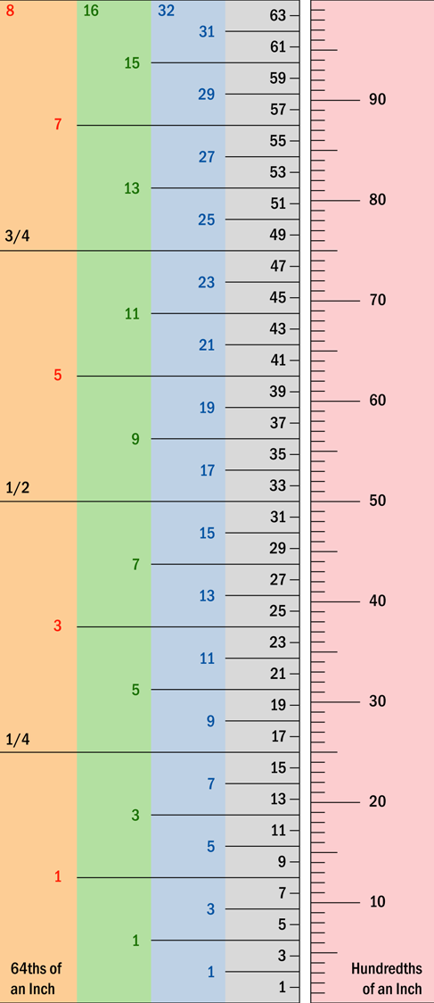
Figure 3-71. For conversion between 64ths of inch and 100ths.

Figure 3-72. For conversion between decimal inch values and 64ths.

Figure 3-73. For conversion between US measurements and metric (millimeters).

Figure 3-74. For conversion between smaller values of US measurements and metric (tenths of millimeters).
Experiment 15: Intrusion Alarm, Part One
Time now for an experiment that takes the knowledge you have acquired and applies it to a simplified but workable consumer product. You may not feel you need an intrusion alarm, but figuring out how to build one will be an excellent introduction to the process of creating circuits to perform tasks in the real world.
I should warn you that designing a circuit from scratch usually leads to unexpected problems and errors. It would be misleading to pretend otherwise. Consequently, in the sequence of steps described below, you’ll find at least one setback and reversal—until we finally end up with a solid, workable system.
What You Will Need
-
9V battery and connector, or 9V AC-DC adapter (your choice)
-
Breadboard, hookup wire, wire cutters, wire strippers, multimeter
-
Generic LED (1)
-
Transistor, 2N2222 (1)
-
DPDT 9VDC relay (1)
-
1N4001 diode (1)
-
Resistors: 470 ohms (1), 1K (1), 10K (1)
Wish List
This experiment is sufficiently complex; it requires a plan. But before I can develop a plan, I need to know what I want. This entails writing what I call a “wish list.” Along the way, I will also try to visualize how each requirement can be satisfied with the components that have been mentioned in previous experiments.
So, what does an intrusion alarm require?
1. Triggering system. The device has to detect if someone has entered the property. A sophisticated system using laser beams or ultrasound would be cool—but too difficult. Because this is a first attempt, I’ll stick with widely available magnetic sensor switches for windows and doors.
2. Sound. The alarm should make some kind of distinctive, attention-getting, fluctuating sound.
3. Tamper-proof. No one should be able to kill the alarm by cutting a wire. In fact, tampering should actually make the alarm go off.
4. Sensors in series. To tamper-proof the system I can run a very small but constant current through a lot of sensor switches that are normally closed, and are wired in series. If any one switch opens, or if the wire itself is broken, this interrupts the current, which will start the alarm. I think most wired alarms are designed on this principle.
5. Off-to-on. If I use sensors in series, an “off” event, caused by opening a switch or breaking the circuit, has to turn the alarm on. Maybe a double-throw relay could do this. Current through the relay coil holds a pair of contacts open, until the flow of current stops, at which point the contacts close by default. But the relay would draw significant power while it’s holding its contacts open. I want my alarm system to draw very little current while it’s in “ready” mode, so that it can be powered by a battery. Alarm systems should never depend entirely on AC house current.
6. Maybe use a transistor? If I don’t use a relay, a transistor could switch on the alarm when the circuit is interrupted. The base of the transistor can be held at a relatively low voltage until the circuit is broken. Then the voltage goes up, and the transistor switches on.
7. Arming the alarm. I need a little light that comes on when all the doors and windows are closed. This tells me that the alarm can be used. Then I want to press a button that starts a one-minute countdown, giving me time to leave. After a minute, the alarm is armed.
8. Self-sustaining. Once the alarm starts, I don’t want it to stop easily. If someone opens a window, the alarm should continue to make a noise even if the person closes the window again. Maybe the transistor can trigger a relay, and when the relay switches on, it keeps itself powered? Or can a transistor do this?
9. Initial delay. I don’t want the alarm to start whooping immediately, each time I walk into the protected area. I want it to wait for a minute, to give me time to reach it and switch it off. If I fail to deactivate it within that time window, then it can start making noise.
10. Deactivation with a code. Some kind of secret-code keypad would be good, to switch off the alarm.
Implementing the Wish List
This wish list sounds a bit ambitious, bearing in mind that the only thing you have built so far is a small oscillator using three transistors. But in fact most of the functions can be implemented fairly easily. I will leave some of the harder ones until later in the book, when I have established a broader knowledge base. In the end, I will be able to deal with everything on the list, and the components will all fit on a single breadboard (with the exception of a noisemaking circuit, which will be optional).
Magnetic Sensor Switches
Let’s start with the component that triggers the alarm. A typical sensor switch consists of two modules: the magnetic module and the switch module. These are shown side by side in Figure 3-75.
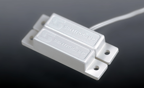
Figure 3-75. A typical alarm sensor consists of a magnet in a plastic pod (bottom left), and a magnetically activated reed switch in a similar pod (top right).
The magnetic module contains a permanent magnet, and nothing else. The switch module contains a reed switch, which makes or breaks a connection (like a contact inside a relay) under the influence of the magnet.
You attach the magnetic module to the moving part of a door or window, and attach the switch module to the window frame or door frame. When the window or door is closed, the magnetic module is almost touching the switch module. The magnet keeps the switch closed—until the door or window is opened, at which point the switch opens. See Figure 3-76 for a cutaway diagram of the magnet-switch combination.
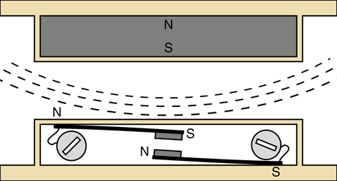
Figure 3-76. This cutaway diagram shows the two components in a typical sensor for an alarm system: a reed switch (bottom) and the magnet that activates it (top).
The switch consists of two flexible magnetized strips terminating in electrical contacts. Each strip connects with an external screw to which a wire can be attached.
When the magnet approaches the switch, it magnetizes the flexible strips, causing them to attract each other until the contacts close.
From my description, you can see that the reed switch is normally open (abbreviated NO), but is kept closed by the magnetic field. If you decide to buy alarm sensors, you should know that some of them contain reed switches that work the other way around. They are normally closed (abbreviated NC), but are opened by the magnetic field. Those are not the ones you want for this project.
A Break-to-Make Transistor Circuit
Now, how can we switch on the noisemaking part of the alarm? Remember, we will have a series of switches that are all normally closed, and when any one of them opens, the alarm must start.
Recall how an NPN transistor works. When the base is not so positive, the transistor blocks current between its collector and emitter. When the base is more positive, the transistor passes current.
Take a look at the schematic in Figure 3-77, which is built around our old friend the 2N2222 NPN transistor. For testing purposes, I have shown a normally closed pushbutton to represent an alarm sensor. I realize that you don’t have a normally closed pushbutton in your supply of parts to build this circuit, but just use your imagination until we’re ready to breadboard it.
So long as the pushbutton remains closed, it connects the base of the transistor to the negative side of the power supply through a 1K resistor. At the same time, the base is connected with the positive side of the power supply through a 10K resistor. Because of the difference in resistances, the base is closer to zero volts than nine volts, holding the transistor below its turn-on threshold. As a result, the transistor will not pass much current, and the LED should not have enough voltage to light up.
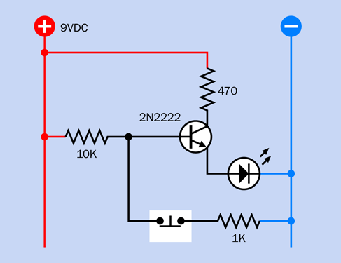
Figure 3-77. A basic circuit in which an LED lights up when a normally closed pushbutton is opened.
Now what happens when the pushbutton is opened? The base of the transistor loses its negative power supply and has only a positive power supply. It becomes much more positive, and tells the transistor to lower its resistance and pass more current. The LED now glows brightly. Thus, when the pushbutton breaks the connection, the LED is turned on.
This seems to be a workable system. Multiple sensors will be needed, for various doors and windows, but that’s OK—we can wire as many as we like in series, as shown in Figure 3-78, where an alarm sensor can be substituted for each pushbutton. The wiring can be laid all around the house, as its total resistance should be low relative to the 10K resistor.
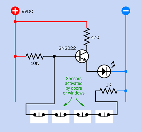
Figure 3-78. In a network of sensors, wired in series, any one sensor will break continuity and trigger the transistor.
While all the sensors remain closed, the transistor is drawing very little current—probably about 1mA. For development and demonstration purposes, you can run it with a 9-volt battery. For actual use, you would really want a 12-volt alarm battery that is maintained by an automatic charging system. That’s outside the scope of this book, but bear in mind that alarm batteries and chargers are widely available if you ever want them.
Now suppose we swap out the LED and put a relay in there instead, as shown in Figure 3-79. (I’ve shown a double-pole relay, even though we have no use for the second pole right now.) So long as all the pushbuttons remain closed, the base of the transistor is held at a relatively low voltage, so the transistor does not apply power to the coil of the relay, and its contacts remain in the state shown.
When any sensor is opened, the higher voltage on the base of the transistor causes it to conduct current to the relay coil, which starts the alarm, as in Figure 3-80. (It’s OK to use a relay in this mode, because the relay will not be “always on.” It will normally be off, and will draw power only when the alarm is triggered.) Note that I eliminated the 470-ohm resistor from the circuit, because the relay doesn’t need any protection from the power supply.
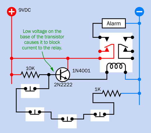
Figure 3-79. In this circuit, the relay will be activated when any switch in the sensor network is opened.
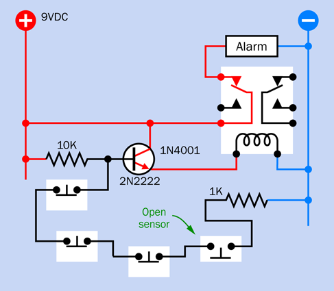
Figure 3-80. Now that a sensor in the circuit is open, the relay is activated by the transistor.
You can build this circuit yourself, using the same relay that you used in Experiment 7 (see “Experiment 7: Investigating a Relay”). But maybe you should wait until I develop it a little further.
A couple of things that you may want to consider:
-
Will the relay overload the transistor? You can find the answer by looking at the datasheets for these two components.
-
Remember that a transistor imposes a small voltage drop, even when it is “on.” Will the voltage still be sufficient to activate a 9-volt relay? The datasheet for the relay will tell you the minimum operating voltage for its coil. You can verify this by testing it.
Self-Locking Relay
The circuit that I have developed so far will activate the alarm when any sensor is opened. That’s good, but what happens if the sensor goes back into its closed state? The low voltage is reapplied to the base of the transistor, so it switches off the alarm. This is not good.
According to item #8 on my wish list, the alarm should be self-sustaining. It must continue making noise even after someone who has opened a door or window closes it again quickly. Therefore, the relay must lock itself on, somehow.
One way to do this would be by using a latching relay, which remains in either of two states, and only requires power to flip from one to the other. But a latching relay has two coils, and would require extra circuitry to unlatch it when you want to turn the alarm off. Really, it’s easier to use a nonlatching relay, and I can think of a way to keep the relay switched on indefinitely, after it has received just one jolt of power.
The secret is revealed in Figure 3-81. In this view, the far-right pushbutton has closed again after being open, so the transistor has switched off—but the relay is still on, because a wire now connects its contacts back to its own coil. When the relay activates the alarm, it also activates itself.
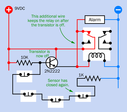
Figure 3-81. The sensor has closed again. The transistor is no longer active, but the alarm is locked on.
Figure 3-82 clarifies this concept by showing the path that current can take. So long as the contacts of the relay are closed, the coil of the relay is energized via its own contacts. In this way, it keeps itself switched on.
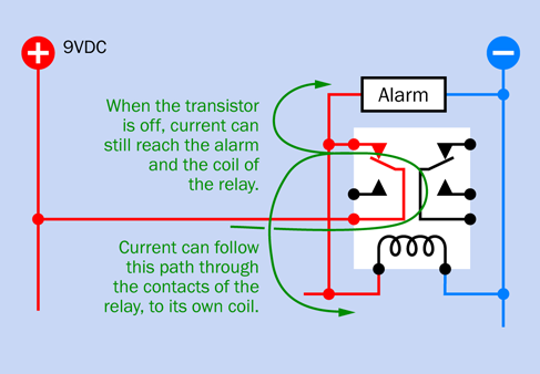
Figure 3-82. Close-up from the previous schematic, showing how the relay keeps itself switched on.
Blocking Bad Voltage
This looks promising, but there’s a problem. The picture in Figure 3-81 was not totally accurate. Take a look at Figure 3-83. The top part of this figure is another close-up of the relevant part of the circuit. When the alarm has locked itself on, but the transistor has turned off, current can run back from the relay coil to the emitter of the transistor. I should have colored this section of wire red, as it will be relatively positive.
Applying power backward through a transistor is not a nice thing to do. It can cause damage. What should be done about this? Maybe I can use something to block this reverse flow: a rectifier diode. This is shown in the bottom half of Figure 3-83.
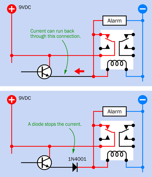
Figure 3-83. A diode can be added to prevent current from forcing its way back into the transistor when the alarm has locked itself on and the transistor switches off.
A new version of the full circuit, including the diode, is shown in Figure 3-84.
But what exactly is a diode? Is it the same as a light-emitting diode (LED)? Well, yes and no.
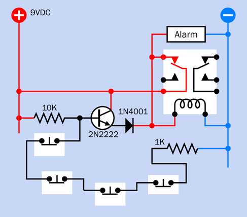
Figure 3-84. The full circuit, now including the diode.
Fundamentals: All About Diodes
A diode is a very early type of semiconductor. It allows electricity to flow in one direction, but blocks it in the opposite direction. Like its more recent cousin, the LED, a diode can be damaged by reversing the voltage and applying excessive power, but most diodes generally have a much greater tolerance for this than LEDs. In fact, they are designed to block reverse voltage, up to a limit specified by the manufacturer.
The end of the diode that stops positive voltage is always marked, usually with a circular band, as shown in Figure 3-25. The marked end is called the cathode. The other end is the anode, and remains unmarked. Diodes are sometimes useful in logic circuits, and can also convert alternating current (AC) into direct current (DC). If a diode isn’t strong enough to withstand the current that you want it to block, you simply use a bigger diode. They come in many sizes.
It’s good practice to use diodes at less than their rated capacity. Like any semiconductor, they can overheat and burn out if they are subjected to mistreatment.
The symbol for a diode looks like the heart of an LED, with the circle and the arrows removed. Three variants are shown in Figure 3-85.

Figure 3-85. Three schematic symbols that are used to represent a diode. They are functionally identical.
One Problem Creates Another
Previously, I had to solve the problem of how to make the relay keep itself switched on. I solved that problem by adding an extra wire, but the wire created a new problem, in which current could flow back to the transistor. I solved that problem by adding a diode, but this creates yet another problem.
We have to pay a fee for the service that the diode provides, just as we have to pay a fee for the service that the transistor provides. In fact, because both of these components are semiconductors, the fee is very similar. It consists of a reduction in voltage.
When the relay is off, current must switch it on by passing through the transistor and then through the diode. After the relay is on, it keeps itself on, and that’s not a problem. But a transistor imposes a penalty of around 0.7V, and the diode imposes an additional penalty of about 0.7V, making 1.4V total. This voltage penalty is fixed, regardless of the supply voltage.
I think 9-volt relays should work reliably at 7.6V. My Omron datasheet tells me that the G5V-2 series, which I have recommended, needs 75% of its supply voltage, which would be only 6.75V. That seems like a reasonable margin of error.
But what if someone substitutes a different relay? Some have narrower specifications than others. Or what if someone is using a battery to power the circuit, and its voltage drops below 9V? A designer should always expect the unexpected, and as a general principle, should use components as close to their rated values as possible.
A couple of readers wrote to me about the issue of voltage reduction when the circuit appeared in the first edition of the book. (Yes, I do pay attention to reader feedback.) At that time, I had specified a 12VDC power source, and felt that the 1.4V penalty imposed by the transistor and the diode would be acceptable. But in this edition, I decided that all the experiments should work with 9VDC power supplies, so that you don’t have to buy an AC adapter and can just use 9V batteries if that’s what you prefer. Unfortunately a deduction of 1.4V from 9V is not so acceptable.
You see how a decision leads to consequences. Now that I am using a 9VDC power supply, I think I need a better way to make the relay lock itself on.
Solving the Problem
The first step to solving a problem is to be very clear about what’s happening.
The task of controlling the alarm is shared by two components: the transistor and the relay. The transistor starts the alarm. After that, the transistor doesn’t do anything. It switches off, and the relay has the task of keeping itself locked on. The weakness in this system is that when a task is shared by two components, they can interfere with each other. A better plan would be to have one component in charge of everything. I should maintain the transistor in a controlling role. It should keep itself turned on, and so long as it is on, it will keep the relay on.
Ah—now I see how to fix it. All I need is to use the second pole of the relay (which is the same relay that you already used in Experiment 7). I can use the contacts in the second pole, which are normally closed, to ground the chain of sensors, as shown in Figure 3-86.
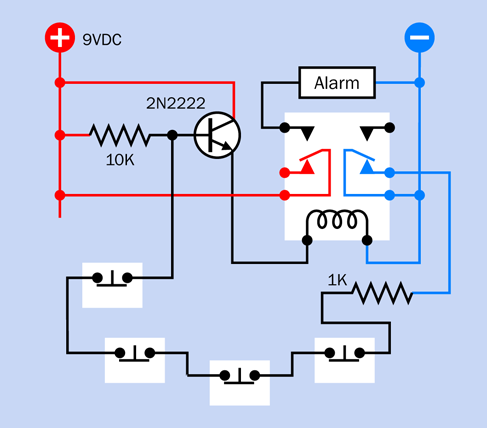
Figure 3-86. The chain of sensors is now grounded through the right-hand contacts in the relay, which are normally closed.
Here’s how it will work:
The base of the transistor now connects to the negative side of the power supply through all the sensors, and the 1K resistor, and the right-hand relay contacts (which are normally closed). So long as this chain of connections is unbroken, the base of the transistor is at a low enough voltage to stop the transistor from passing current.
Now someone opens a sensor. The base of the transistor isn’t grounded anymore, so the transistor activates the relay. The relay closes the left-hand contacts, which start the alarm. But the relay also opens the right-hand contacts.
Now if someone re-closes the sensor, it makes no difference anymore, because the right-hand contacts of the relay are open, and have cut off the connection to the negative side of the power supply. The transistor continues to pass current, and the relay remains active. This is shown in Figure 3-87.
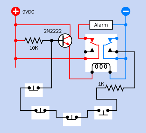
Figure 3-87. Now that a sensor has been opened, the transistor remains energized even if the sensor is subsequently closed.
This solves the problem.
Protection Diode
As you saw above, I eliminated the diode from the circuit. But if you take a look at Figure 3-88 (which I promise is the last version, at least for now) you will notice that the diode has found its way back in again, although it’s doing something very different. It is now in parallel with the coil of the relay. What’s it doing there, of all places?
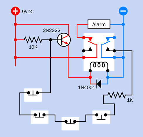
Figure 3-88. The diode has returned, now serving a function as a protection diode.
Much later in the book, I’ll be discussing coils. One thing I can tell you right now is that a coil of wire stores energy when you apply power, and releases the energy when you disconnect the power. The release of energy creates a surge of current that can harm some types of components, especially semiconductors.
Therefore, it is standard procedure to add a protection diode across a relay coil. The diode is oriented so that it blocks the normal flow of current, forcing it to go through the coil, which is where we want it. But when the flow stops, and the coil tries to release its energy, the diode is there, saying to the relay, “I have a very low resistance in that direction. Why don’t you shunt the current through me, instead of hassling the other components with it?”
And that is precisely what happens.
If you’re only using a small relay with a small coil that doesn’t take much current, you can get by without using a protection diode. Still, it’s good practice, and you should always be in the habit of using one.
Time to Breadboard
I’ve given you a lot of explanations in this experiment, which is not what I normally like to do. But I had to show how a circuit is developed from the ground up. Now, finally, I’d like you to build it—otherwise, how will you know if it really works?
Figure 3-89 shows a breadboard layout. Instead of a noisemaker for the alarm, I’ve used an LED for demonstration purposes. I’ll discuss noisemaking options in a moment.
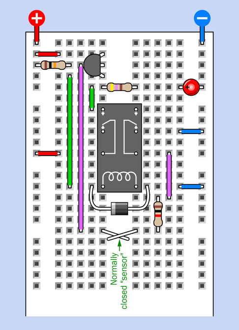
Figure 3-89. Breadboarded alarm circuit, final version.
Figure 3-90 shows an x-ray view of the breadboarded circuit
To simulate the alarm sensors on the breadboard, I should have used normally closed pushbuttons. But I wanted to minimize the component costs, and if you actually decide to use this alarm circuit, you’ll want magnetic sensors, not pushbuttons. Consequently, as a substitute, I used two normally closed pieces of wire. This is adequate for testing. I will call them the “sensor wires.” You can see them crossing over each other below the relay.
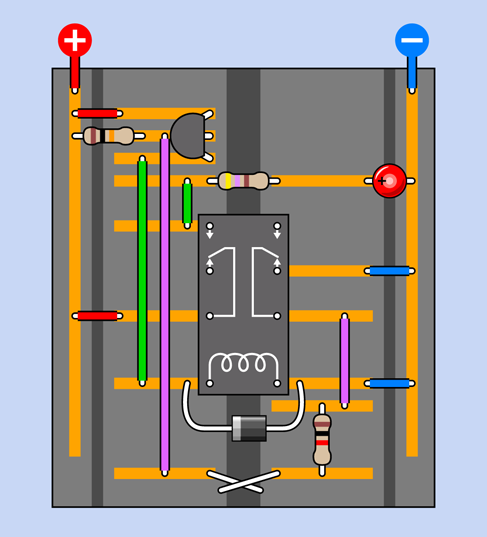
Figure 3-90. X-ray view of the breadboarded alarm circuit.
Make sure the wires are touching each other when you apply power to the circuit. Initially, nothing should happen.
Now disconnect the sensor wires. The LED comes on, and if you build the next version of this circuit, a noisemaker will sound, showing that the alarm has been triggered.
Now reconnect the sensor wires, imitating a situation where an intruder opened a window, heard the alarm, and quickly closed the window again. If you wired your circuit correctly, the LED will stay on.
So far so good. We have a functional circuit here. The alarm locks itself on.
But in that case—how do you ever get it to stop?
No problem. Just disconnect the power. The relay relaxes back to its default position, and the next time you apply the power, it will be in standby mode again. In a finished version of this project, you should have to enter some kind of secret code on a keypad to turn the alarm off. In Experiment 21, I’ll be suggesting a way to create a passcode-protected system. You’ll need to use logic chips, which we haven’t dealt with yet.
Adding the Sound
For the alarm sound, you could use the oscillator circuit and loudspeaker from Experiment 11. Really, though, there is a better way. A little integrated circuit chip known as a 555 timer is a better tool for the job—and it just happens to be the next thing that I want to tell you about, in Experiment 16.
The 555 timer can also satisfy items #7 and #9 on my wish list, which require a delay before the alarm starts. Therefore, I’m going to put the alarm project on hold, and we’ll finish it completely in Experiment 18.
Reference: Take-Home Messages
Even though the alarm project isn’t finished yet, it raised several important points. I’m going to summarize them here, for future reference.
-
You can use a transistor to provide a high output in response to a low input, and vice versa.
-
You can wire a relay to lock itself into “on” mode, simply by feeding current back to its own coil.
-
A diode can stop current from flowing into places where you don’t want it to go.
-
When forward current passes through a diode, the voltage is reduced by about 0.7V.
-
A transistor also reduces voltage by about 0.7V.
-
Voltage reduction imposed by semiconductors remains the same regardless of the supply voltage. Consequently, the reduction is more significant when the supply voltage is lower.
-
A relay coil can create back-EMF (a pulse of reverse current) when it is switched off.
-
A protection diode in parallel with a relay coil can suppress back-EMF. The diode should be oriented so that it blocks the normal flow of current but passes the reverse pulse created by the coil.