Chapter 5. What Next?
At this point, we can branch out in numerous directions. Here are some possibilities:
Audio: This is a large field including hobby projects such as amplifiers and “stomp boxes,” to modify guitar sound.
Electromagnetism: This is a topic that I haven’t even mentioned yet, but it has some fascinating applications.
Radio-frequency devices: Anything that receives or transmits radio waves, from an ultra-simple AM radio onward.
Programmable microcontrollers: These are tiny computers on a single chip. You write a little program on your desktop computer, and load it into the chip. The program tells the chip to follow a sequence of procedures, such as receiving input from a sensor, waiting for a fixed period, and sending output to a motor. Popular controllers include the Arduino, PICAXE, BASIC Stamp, and many more.
I don’t have space to develop all of these topics fully, so what I’m going to do is introduce you to them by describing just a few projects in each category. You can decide which interests you the most, and then proceed beyond this book by reading other guides that specialize in that interest.
I’m also going to make some suggestions about setting up a productive work area, reading relevant books, catalogs, and other printed sources, and generally proceeding further into hobby electronics.
Tools, Equipment, Components, and Supplies
No additional tools or equipment are needed for this final chapter of the book. For a summary of all the components, see Figure 6-8. See “Supplies” for a list of additional supplies (primarily wire, for the coils in Experiments 25, 26, 28, 29, and 31).
Customizing Your Work Area
At this point, if you’re getting hooked on the fun of creating hardware but haven’t allocated a permanent corner to your new hobby, I have some suggestions. Having tried many different options over the years, my main piece of advice is this: don’t build a workbench!
Many hobby electronics books want you to go shopping for 2 × 4s and plywood, as if a workbench has to be custom-fabricated to satisfy strict criteria about size and shape. I find this puzzling. To me, the size and shape is not very important. I think the most important issue is storage.
I want tools and parts to be easily accessible, whether they’re tiny transistors or big spools of wire. I certainly don’t want to go digging around on shelves that require me to get up and walk across the room.
This leads me to two conclusions:
-
You need storage around the workbench.
-
You need storage below the workbench.
Many DIY workbench projects allow little or no storage underneath. Or, they suggest open shelves, which will be vulnerable to dust. My minimum configuration would be a pair of two-drawer file cabinets with a slab of 3/4-inch plywood or a Formica-clad kitchen countertop placed across them. File cabinets are ideal for storing all kinds of objects, not just files, and you can often find cheap ones at yard sales and thrift stores.
Of all the workbenches I’ve used, the one I liked best was an old-fashioned steel office desk—the kind of monster that dates back to the 1950s. They’re difficult to move (because of their weight) and don’t look beautiful, but you can buy them cheaply from used office furniture dealers, they’re generous in size, they withstand abuse, and they last forever. The drawers are deep and usually slide in and out smoothly, like good file-cabinet drawers. Best of all, the desk has so much steel in it that you can use it to ground yourself before touching components that are sensitive to static electricity. If you use an antistatic wrist strap, you can simply attach it to a sheet-metal screw that you drive into one corner of the desk.
What will you put in the deep drawers of your desk or file cabinets? Some paperwork may be useful, perhaps including the following documents:
-
Product datasheets
-
Parts catalogs
-
Sketches and plans that you draw yourself
The remaining capacity of each drawer can be filled with plastic storage boxes. The boxes can contain tools that you don’t use so often (such as a heat gun or a high-capacity soldering iron), and larger-sized components (such as loudspeakers, AC adapters, project boxes, and circuit boards). You should look for storage boxes that measure around 11 inches long, 8 inches wide, and 5 inches deep, with straight sides. Boxes that you can buy at Walmart will be cheaper, but they often have tapering sides, which are not space-efficient.
The boxes that I like best are Akro-Grids, made by Akro-Mils (see Figure 5-1 and Figure 5-2). These are very rugged, with optional transparent snap-on lids. Perspective in the photographs make the boxes look as if they taper downward, but they don’t. You can download the full Akro-Mills catalog online and then search online for retail suppliers. You’ll find that Akro-Mils also sells an incredible variety of parts bins, but I don’t like open bins because their contents are vulnerable to dust and dirt.
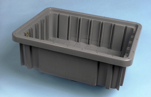
Figure 5-1. Akro-Grid boxes contain grooves allowing them to be partitioned into numerous compartments for convenient parts storage. The height of the box in this photograph allows three to be stacked in a typical file-cabinet drawer.
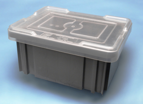
Figure 5-2. Lids are sold separately for Akro-Grid boxes to keep the contents dust-free. The taller box shown here allows two to be stacked in a file-cabinet drawer.
For medium-size components, such as potentiometers, power connectors, control knobs, and toggle switches, I like storage containers measuring about 11 inches long, 8 inches wide, and 2 inches deep, divided into four to six sections. You can buy these from Michaels (the craft store), but I prefer to shop online for the Plano brand, as they seem more durably constructed. The Plano products that are most suitable for medium-size electronic parts are classified as fishing-tackle boxes.
For undivided, flat-format storage boxes, the Prolatch 23600-00 is ideally sized to fit a file-cabinet drawer, and the latches are sufficiently secure that you could stack a series of them on their long edges. See Figure 5-3.
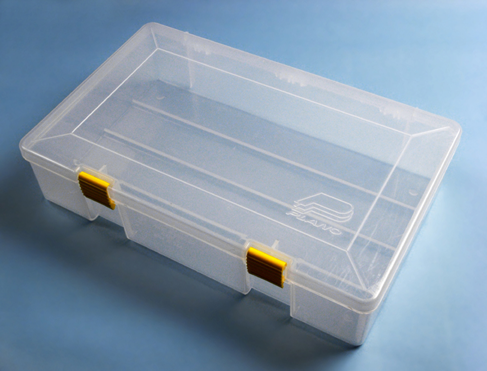
Figure 5-3. This Plano brand box is undivided, making it useful for storing spools of wire or medium-size tools. When stacked upright on its long edge, three will fit precisely in a file-cabinet drawer.
Plano also sells some really nicely designed toolboxes, one of which you can place on your desktop. It will have small drawers for easy access to screwdrivers, pliers, and other basics. Because you need a work area that’s only about three feet square for most electronics projects, surrendering some desk space to a toolbox is not a big sacrifice.
If you have a steel desk with relatively shallow drawers, one of them can be allocated for printed catalogs. Don’t underrate the usefulness of hardcopy, just because you can buy everything online. The Mouser catalog, for instance, has an index, which is more useful in some respects than their online search feature, and the catalog is divided into helpful categories. Many times I’ve found useful parts that I never knew existed, just by browsing, which is much quicker than flipping through PDF pages online, even with a broadband connection. Currently, Mouser is still quite generous about sending out their catalogs, which contain over 2,000 pages. McMaster-Carr will also send you a catalog, but only after you’ve ordered from them, and only once a year. It is probably the most comprehensive, most wonderful catalog of tools and hardware in the world.
Now, the big question: how to store all the dinky little parts, such as resistors, capacitors, and chips? I’ve tried various solutions to this problem. The most obvious is to buy a case of small drawers, each of which is removable, so you can place it on your desk while you access its contents. But I don’t like this system, for two reasons. First, for very small components, you need to subdivide the drawers, and the dividers are never secure. And second, the removability of the drawers creates the risk of accidentally emptying the contents on the floor. Maybe you’re too careful to allow this to happen, but I’m not. In fact, on one occasion I tipped the entire case of drawers onto the floor.
My personal preference is to use Darice Mini-Storage boxes, shown in Figure 5-4. You can find these at Michaels in small quantities, or buy them more economically in bulk online—just search for:
darice mini storage box
The blue boxes are subdivided into five compartments that are exactly the right size and shape for resistors. The yellow boxes are subdivided into 10 compartments, which are ideal for semiconductors. The purple boxes aren’t divided at all, and the red boxes have a mix of divisions. All the boxes share the same stock number: 2505-12.
The dividers are molded into the boxes, so you don’t have the annoyance associated with removable dividers that slip out of position, allowing components to mix together. The box lids fit tightly, so that even if you drop one of the boxes, it probably won’t open. The lids have metal hinges, and a ridge around the edge that makes the boxes securely stackable.

Figure 5-4. Darice Mini-Storage boxes are ideal for components such as resistors, capacitors, and semiconductors. The boxes can be stacked stably, stored on shelves, or grouped in larger boxes. The brand sticker is easily removed after being warmed with a heat gun.
After considerable searching, I found cheap plastic bins, with lids, measuring about 8 inches by 13 inches by 5 inches deep. Each bin will hold nine Darice parts boxes. The bins can then be categorized and stored on shelves.
Labeling
No matter which way you choose to store your parts, labeling them is essential. Any ink-jet printer will produce neat-looking labels, and if you use peelable (nonpermanent) labels, you’ll be able to reorganize your parts in the future, as always seems to become necessary. I use color-coded labels for my collection of resistors, so that I can compare the stripes on a resistor with the code on the label, and see immediately if the resistor has been put in the wrong place. See Figure 5-5.
Even more important: you need to place a second (non-adhesive) label inside each compartment with the components. This label tells you the manufacturer’s part number and the source, so that reordering is easy. I buy a lot of items from Mouser, and whenever I open their little plastic bags of parts, I snip out the section of the bag that has the identifying label on it, and slide it into the compartment of my parts box before I put the parts on top of it. This saves frustration later.

Figure 5-5. To check that resistors are not placed in the wrong compartments, print the color code on each label.
If I were really well organized, I would also keep a database on my computer listing everything that I buy, including the date, the source, the type of component, and the quantity. But I’m not that well organized.
On the Bench
Some items are so essential that they should sit on the bench or desktop on a permanent basis. These include your soldering iron(s), Helping Hand with magnifier, desk lamp, breadboard, power strip, and power supply. For a desk lamp, I prefer to use one that contains an LED bulb, for reasons explained in Experiment 14.
A power supply for your projects is a matter of personal preference. If you’re serious about electronics, you can buy a unit that delivers properly smoothed current at a variety of properly regulated and calibrated voltages. Your little wall-plug AC adapter cannot do this, and its output may vary depending on how heavily you load it. Still, as you’ve seen, it is sufficient for basic experiments, and when you’re working with logic chips, you need to mount a 5-volt regulator on your breadboard anyway. Overall, I consider a good power supply optional.
Another optional item is an oscilloscope. This will show you, graphically, the electrical fluctuations inside your wires and components, and by applying probes at different points, you can track down errors in your circuit. It’s a neat gadget to own, but it will cost a few hundred dollars, and for our tasks so far, it has not been necessary. If you plan to get seriously into audio circuits, an oscilloscope becomes far more important, because you’ll want to see the shapes of the waveforms that you generate.
You can try to economize on an oscilloscope by buying a unit that plugs into the USB port of your computer and uses your computer monitor to display the signal. I have tried one of these, and was not entirely happy with the results. It worked, but did not seem accurate or reliable for low-frequency signals. Maybe I was unlucky, but I decided not to try any other brands.
The surface of your desk or workbench will undoubtedly become scarred by random scuffs, cut marks, and drops of molten solder. I use a piece of half-inch plywood, two feet square, to protect my primary work area, and I clamp a miniature vise to its edge. In the past I used to cover the plywood with a square of conductive foam, to reduce the risk of static discharge from me to sensitive components. Over the years, though, I realized that my particular combination of carpet, chair, and shoes does not cause me to suffer from static. This is a matter for you to determine by experience. If you see a tiny little spark sometimes when you touch a metal object, and you feel a little zap of electricity, you need to consider grounding yourself and perhaps using anti-static foam (or a piece of metal) on your working surface.
Inevitably, during your work you’ll create a mess. Little pieces of bent wire, stray screws, fasteners, and fragments of stripped insulation tend to accumulate, and can be a liability. If metal parts or fragments get into a project that you’re building, they can cause short circuits. So you need a trash container. But it has to be easy to use. I use a full-size garbage pail, because it’s so big that I can’t miss it when I throw something toward it, and I can never forget that it’s there.
Last, but most essential: a computer. Now that all datasheets are available online, and all components can be ordered online, and many sample circuits are placed online by hobbyists and educators, I don’t think anyone can work efficiently without quick Internet access. To avoid wasting space, you can place a tower computer on the floor and mount its monitor on the wall—or use a tablet, or a small, cheap laptop that has a minimal footprint.
A possible workbench configuration, using a steel desk, is shown in Figure 5-6. A more space-efficient configuration is suggested in Figure 5-7.
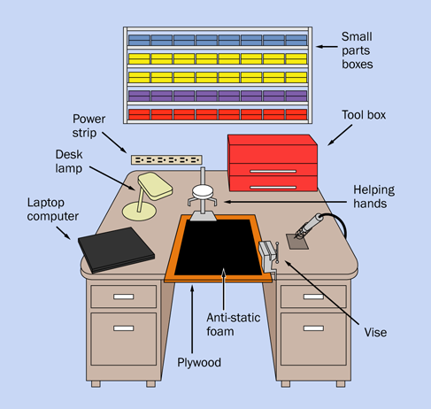
Figure 5-6. An old steel office desk can be as good as, if not better than, a conventional workbench when building small electronics projects. It provides a large work area and ample storage, and has sufficient mass for you to ground yourself when dealing with components that are sensitive to static electricity.
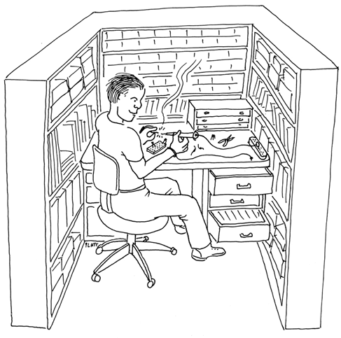
Figure 5-7. For maximum utilization of available space, consider walling yourself in.
Reference Sources Online
When people ask me to recommend a website offering basic information at entry level, I recommend Doctronics.
I like the way they draw their schematics, and I like the way they include many illustrations of circuits on breadboards, as I do myself. They also sell kits, if you’re willing to pay and wait for shipping from the UK.
My next favorite hobby site is also British-based: the Electronics Club. It’s not as comprehensive as Doctronics, but very friendly and easy to understand.
For a more theory-based approach, try ElectronicsTutorials.
This will go a little farther than the theory sections I’ve included here.
For an idiosyncratic selection of electronics topics, try Don Lancaster’s Guru’s Lair.
Lancaster wrote The TTL Cookbook more than 30 years ago, which opened up electronics to at least two generations of hobbyists and experimenters. He knows what he’s talking about, and isn’t afraid of getting into some fairly ambitious areas such as writing his own PostScript printer drivers and creating his own serial-port connections. You’ll find a lot of ideas there.
Books
Yes, you do need books. A few of the ones I use are stacked up in Figure 5-8.
As you’re already reading this one, I won’t recommend other beginners’ guides. Instead, I’ll suggest some titles that will take you farther in various directions, and can be used for reference.
Make: More Electronics is the sequel that I wrote to this book, which includes all the topics (such as op-amps) for which I did not have space here. Some of the circuits are more ambitious. If you read that book, and this book, you will cover most aspects of electronics that are accessible to an individual on a moderate budget.

Figure 5-8. A sun-damaged copy of Don Lancaster’s classic guide to TTL chips remains at the top of my stack of reference books. It opened up a whole new era of hobby electronics more than 40 years ago. Much of its information is still useful, and copies are available from secondhand sources, including Amazon.
The Encyclopedia of Electronic Components is a project that I began before I realized quite how demanding it would be. Consequently, its three volumes were repeatedly delayed. Volumes 1 and 2 are in print as I write this. By the time you read this, maybe Volume 3 will be in print too. The idea of these books is that they are ideal for quick reference. They can remind you of what you forgot, and they go into a lot of detail. By comparison, Make: Electronics is a teaching guide full of hands-on tutorials, in which I try not to get bogged down in detail.
Now let me list the books that I consider most important, written by other people:
Practical Electronics for Inventors, by Paul Scherz with Simon Monk (McGraw-Hill, Second Edition, 2013): This is a massive, comprehensive book, well worth the $40 cover price. Despite its title, you won’t need to invent anything to find it useful. It’s my primary reference source, covering a wide range of concepts, from the basic properties of resistors and capacitors all the way to some fairly highend math.
Getting Started with Arduino, by Massimo Banzi and Michael Shiloh (Make, 2014): This is the simplest introduction around, and will help to familiarize you with the processing language used in Arduino (similar to the C language, if you know anything about that).
Making Things Talk, by Tom Igoe (Make: Books, 2011): This ambitious and comprehensive volume shows how to make the most of the Arduino’s ability to communicate with its environment, even getting it to access sites on the Internet.
TTL Cookbook, by Don Lancaster (Howard W. Sams & Co, 1974): The 1974 copyright date is not a misprint! You may be able to find some later editions, but whichever one you buy, it will be secondhand. Lancaster wrote his guide before the 74xx series of chips was emulated on a pin-for-pin basis by CMOS versions such as the 74HCxx series, but it’s still a good reference, because the concepts and part numbers haven’t changed, and his writing is so accurate and concise. Just bear in mind that his information about high and low logic voltages is no longer accurate.
CMOS Sourcebook, by Newton C. Braga (Sams Technical Publishing, 2001): This book is entirely devoted to the 4000 series of CMOS chips, not the 74HCxx series that I’ve dealt with primarily here. The 4000 series is older and must be handled more carefully, because it’s more vulnerable to static electricity than the generations that came later. Still, the chips remain widely available, and their great advantage is their willingness to tolerate a wide voltage range, typically from 5 to 15 volts. This means you can set up a 12-volt circuit that drives a 555 timer, and use output from the timer to go straight into CMOS chips (for example). The book is well organized in three sections: CMOS basics, functional diagrams (showing pinouts for all the main chips), and simple circuits showing how to make the chips perform basic functions.
The Encyclopedia of Electronic Circuits, by Rudolf F. Graf (Tab Books, 1985): A totally miscellaneous collection of schematics, with minimal explanations. This is a useful book to have around if you have an idea and want to see how someone else approached the problem. Examples are often more valuable than general explanations, and this book is a massive compendium of examples. Many additional volumes in the series have been published, but start with this one, and you may find it has everything you need.
The Circuit Designer’s Companion, by Tim Williams (Newnes, Second Edition, 2005): Much useful information about making things work in practical applications, but the style is dry and fairly technical. May be useful if you’re interested in moving your electronics projects into the real world.
The Art of Electronics, by Paul Horowitz and Winfield Hill (Cambridge University Press, Second Edition, 1989): The fact that this book has been through 20 printings tells you two things: (1) many people regard it as a fundamental resource; (2) secondhand copies should be widely available, which is an important consideration, as the list price is over $100. It’s written by two academics, and has a more technical approach than Practical Electronics for Inventors, but I find it useful when I’m looking for backup information.
Getting Started in Electronics, by Forrest M. Mims III (Master Publishing, Fourth Edition, 2007): Although the original dates back to 1983, this is still a fun book to have. I think I have covered many of its topics here, but you may benefit by reading explanations and advice from a completely different source, and it goes a little farther than I have into some electrical theory, on an easy-to-understand basis, with cute drawings. Be warned that it’s a brief book with eclectic coverage. Don’t expect it to have all the answers.
Experiment 25: Magnetism
Now that I have surveyed your future options, let me deal with a very important topic that has been waiting in the background: the relationship between electricity and magnetism. Quickly this will lead us into audio reproduction and radio, and I’ll describe the fundamentals of self-inductance, which is the third and final basic property of passive components (resistance and capacitance being the other two). I left self-inductance until last because it has limited application to DC circuits. But as soon as we start dealing with analog signals that fluctuate, it becomes fundamental.
Fundamentals: A Two-Way Relationship
Electricity can create magnetism:
This principle is used in almost every electric motor in the world.
Magnetism can create electricity:
-
When a wire moves through a magnetic field, the field creates a flow of electricity in the wire.
This principle is used in power generation. A diesel engine, or a water-powered turbine, or a windmill, or some other source of energy can turn coils of wire through a powerful magnetic field. Electricity is induced in the coils. With the exception of solar panels, all practical sources of electric power use magnets and coils of wire.
In the next experiment, you’ll see a dramatic mini-demo of this effect. It should be a part of any school science class, but even if you’ve done it in the past, I suggest that you do it again, because setting it up takes only a matter of moments.
What You Will Need
-
Large screwdriver (1)
-
22-gauge wire, or thinner (no more than 6 feet)
-
9-volt battery (1)
-
Paper clip (1)
Procedure
This couldn’t be simpler. Wind the wire around the shaft of the screwdriver, near its tip. The turns should be neat and tight and closely spaced, and you’ll need to make 100 of them, within a distance of no more than 2 inches. To fit them into this space, you’ll have to make turns on top of previous turns. If the final turn tends to unwind itself, secure it with a piece of tape.
Now apply the 9-volt battery. At first sight, this looks like a very bad idea, because you’re going to short out your battery just as you did in Experiment 2. But when you pass current through a wire that’s coiled instead of straight, the flow of current is inhibited (in a way that I will explain shortly), and the current does some work (such as, it can move a paper clip).
Put a small paper clip near the screwdriver blade, as shown in Figure 5-9.
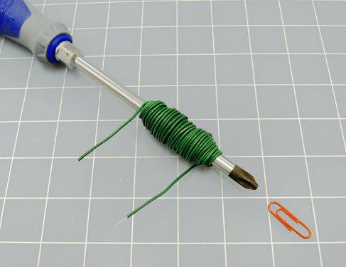
Figure 5-9. This most basic electromagnet is just strong enough to attract a paper clip.
The surface should be smooth, so that the paper clip can slide across it easily. Because many screwdrivers are already magnetic, you may find that the paper clip is naturally attracted to the tip of the blade. If this happens, move the clip just outside the range of attraction. Now apply the 9 volts to the circuit, and the clip should jump to the tip of the screwdriver.
Congratulations: you just made an electromagnet. The schematic is shown in Figure 5-10.

Figure 5-10. A schematic can’t get much simpler than this.
Theory: Inductance
When electricity flows through a wire, it creates a magnetic field around the wire. Because the electricity “induces” this effect, it is known as inductance. This is illustrated in Figure 5-11.
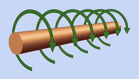
Figure 5-11. When the flow of electricity is from left to right along this conductor, it induces a magnetic force shown by the green arrows.
The field around a straight wire is very weak, but if we bend the wire into a circle, the magnetic force starts to accumulate, pointing through the center of the circle, as shown in Figure 5-12. If we add more circles, to form a coil, the force accumulates even more. And if we put a steel or iron object (such as a screwdriver) in the center of the coil, the effectiveness increases further.
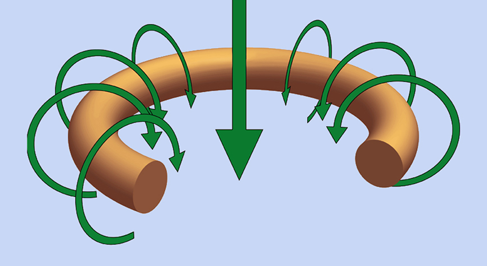
Figure 5-12. When the conductor is bent to form a circle, the cumulative magnetic force acts through the center of the circle, as shown by the large arrow.
Figure 5-13 shows this graphically, along with a formula known as “Wheeler’s approximation,” which allows you to calculate the inductance of a coil approximately, assuming you know the inner radius, the outer radius, the width, and the number of turns. (The dimensions must be in inches, not metric.) The basic unit of inductance is the henry, named after American electrical pioneer Joseph Henry. Because this is a large unit (like the farad), the formula expresses inductance in microhenries.
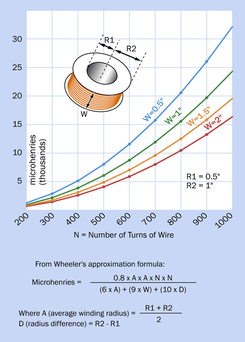
Figure 5-13. A graphical representation showing how the dimensions and number of turns in a coil affect its inductance, calculated approximately with a simple formula.
You’ll see from the graphs that if you keep the basic size of a coil the same, and double the number of turns (by using thinner wire or wire with thinner insulation), the reactance of the coil increases by a factor of four. This is because the formula includes the factor N x N at the top. Here are some take-home messages:
-
Inductance increases with the diameter of the coil.
-
Inductance increases approximately with the square of the number of turns. (In other words, three times as many turns create nine times the inductance.)
-
If the number of turns remains the same, inductance is lower if you wind the coil so that it’s slender and long, but is higher if you wind it so that it’s fat and short.
Fundamentals: Coil Schematics and Basics
Check the schematic symbols for coils in Figure 5-14. Moving from left to right, either of the first two symbols represents a coil with an air core (the first symbol is older than the second). The third and fourth symbols indicate that the coil is wound around a solid iron core, or a core composed of iron particles or ferrite, respectively.

Figure 5-14. Schematic symbols to represent coils. See text for details.
An iron core will add to the inductance of a coil, because it increases the magnetic effect.
If you measure the magnetic field created by a coil with a positive power source at one end and negative ground at the other end, the field will reverse if you reverse the polarity of the power supply.
Perhaps the most widespread application of coils is in transformers, where alternating current in one coil induces alternating current in another, often sharing the same iron core. If the primary (input) coil has half as many turns as the secondary (output) coil, the voltage will be doubled, at half the current—assuming hypothetically that the transformer is 100% efficient.
Background: Joseph Henry
Born in 1797, Joseph Henry was the first to develop and demonstrate powerful electromagnets. He also originated the concept of “self-inductance,” meaning the “electrical inertia” that is a property of a coil of wire.
Henry started out as the son of a day laborer in Albany, New York. He worked in a general store before being apprenticed to a watchmaker, and was interested in becoming an actor. Friends persuaded him to enroll at the Albany Academy, where he turned out to have an aptitude for science. In 1826, he was appointed Professor of Mathematics and Natural Philosophy at the Academy, even though he was not a college graduate and described himself as being “principally self-educated.” Michael Faraday was doing similar work in England, but Henry was unaware of it.
Henry was appointed to Princeton in 1832, where he received $1,000 per year and a free house. When Morse attempted to patent the telegraph, Henry testified that he was already aware of its concept, and indeed had rigged a system on similar principles to signal his wife, at home, when he was working in his laboratory at the Philosophical Hall.
Henry taught chemistry, astronomy, and architecture, in addition to physical science, and because science was not divided into strict specialties as it is now, he investigated phenomena such as phosphorescence, sound, capillary action, and ballistics. In 1846, he headed the newly founded Smithsonian Institution as its secretary. His photograph appears in Figure 5-15.

Figure 5-15. Joseph Henry was an American experimenter who pioneered the investigation of electromagnetism. This photograph is archived in Wikimedia Commons.
Experiment 26: Tabletop Power Generation
In Experiment 5, you saw that chemical reactions can generate electricity. Now it’s time to see electricity generated by a magnet.
What You Will Need
-
Wire cutters, wire strippers, test leads, multimeter
-
Cylindrical neodymium magnet, 3/16” diameter by 1.5” long, axially magnetized (1)
-
Hookup wire, 26-gauge, 24-gauge, or 22-gauge, total 200 feet
-
Low-current LED (1)
-
Capacitor, 1,000µF (1)
-
Switching diode, 1N4001 or similar (1)
Optional extras:
-
Cylindrical neodymium magnet, 3/4” diameter by 1” long, axially magnetized (1)
-
Half-inch diameter wooden dowel, 6” long (minimum)
-
Steel screw, #6 size with flat head
-
PVC water pipe, 3/4” internal diameter, 6” long (minimum)
-
Two pieces of 1/4” plywood, each about 4” x 4” (you will need a 1” hole saw or Forstner bit to drill a hole through the plywood)
-
Spool of magnet wire, quarter-pound, 26-gauge, about 350 feet (1)
Procedure
First, you need a magnet. Neodymium magnets are the strongest available, and are fairly cheap if you choose the small cylindrical type. A magnet of just 3/16” diameter and 1.5” long will be sufficient. Wrap about 10 turns of 22-gauge wire tightly around it, as shown in Figure 5-16. Now allow the wire to loosen slightly, so that the magnet can slide through the coils.
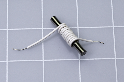
Figure 5-16. Just ten turns of wire can be sufficient to create a small electrical potential when a magnet moves through them.
Set your meter to measure millivolts AC (not DC, because we’re going to be dealing with alternating pulses of electricity). Strip a little insulation from each end of the coil, and use alligator test leads to attach the meter. Grasp the magnet between finger and thumb, and shuttle it quickly to and fro inside the coil. I’m guessing you’ll see a value of 3mV to 5mV on your meter. Yes, this small magnet, and 10 turns of wire, can generate a few millivolts.
Try winding a bigger coil, with the layers overlapping, as shown in Figure 5-17. Move the magnet quickly again. You should find that you are generating more voltage.

Figure 5-17. Adding more turns of wire will increase the measured voltage when the magnet moves through them.
Remember the formula from the previous experiment, in which I showed how passing electricity through more coils of wire would induce a stronger magnetic field. It works both ways:
-
More coils of wire will generally induce a higher voltage, when a magnet moves through the coils.
This leads me to wonder—if we had a bigger, stronger magnet and a lot of turns of wire, could we generate enough electricity to power something, such as, maybe, an LED?
Lighting an LED
I’m going to use 22-gauge wire, because you already have it for the other experiments. The trouble is, it is relatively thick and has thick insulation. Two hundred turns of this wire really begin to bulk up. This is why we should be using magnet wire, which is pure copper wire with an ultra-thin coating of insulation made from shellac or plastic film. Magnet wire is designed to pack as densely as possible.
However, you may not feel like spending the money for a spool of magnet wire, bearing in mind that you are unlikely to find any other use for it. So, I decided to see if 22-gauge hookup wire would be workable in this experiment. The answer is yes, but only just.
You do need 200 feet. That will cost a bit of money, but you can always reuse the wire for normal purposes, such as creating jumpers for breadboards.
You can join two or more pieces of wire together when you are winding a spool, and so long as you twist the stripped ends tightly, you don’t need to solder them.
You also need a more powerful magnet. The smallest that worked for me is cylindrical, measures 1” long and 3/4” in diameter, and is axially magnetized, meaning that the north and south poles are at opposite ends of its axis. (The axis is an imaginary line that runs through the center of the cylinder, parallel with its curved sides. You can imagine the cylinder like a shaft rotating around its axis.)
The equipment that I ended up with is shown in Figure 5-18. The magnet is at the right-hand side. The spool I made from 1/4” plywood, and it is just over four inches in diameter. A piece of 3/4” PVC water pipe runs through the center, and its inside diameter is just a fraction wider than the diameter of the magnet, so that the magnet can slide through it freely.
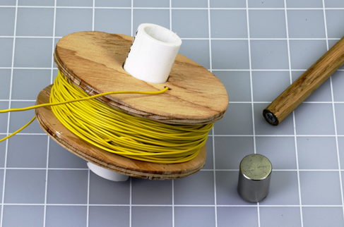
Figure 5-18. Two hundred turns of 22-gauge wire on a home-made spool, with a magnet that attaches itself to a screw in a wooden dowel.
Push-fit the plywood circles onto the pipe, to create a spool. Now you need to wind 200 feet of wire onto the spool—taking care to leave access to the inside end of the wire. I drilled a small hole in one of the plywood circles, near the center, and poked the wire out through the hole.
The width of the coil that you are going to wind should be about the same as the length of the magnet, and the magnet inside the tube should be able to emerge completely on either side of the coil. The cross-section of the spool in Figure 5-19 shows what I mean.
To hold the magnet conveniently, I drilled a hole in one end of a piece of 1/2” wooden dowel, and inserted a #6 1” flat-headed screw. I was then able to hold the dowel like a handle, while the magnet attracted itself firmly to the screw.
Now for the big moment. Use a couple of alligator test leads to attach the ends of your coil to the inputs of your meter, and set the meter to AC volts, as you did before. This time, though, set it to measure up to 2 volts.
With the magnet attached to the dowel, you can push it as quickly as possible in and out of the PVC pipe. Alternatively, remove the magnet from the dowel, drop it into the pipe, and rattle it up and down with your finger and thumb over the ends of the pipe. If you really work hard, your meter should show a voltage of around 0.8V.
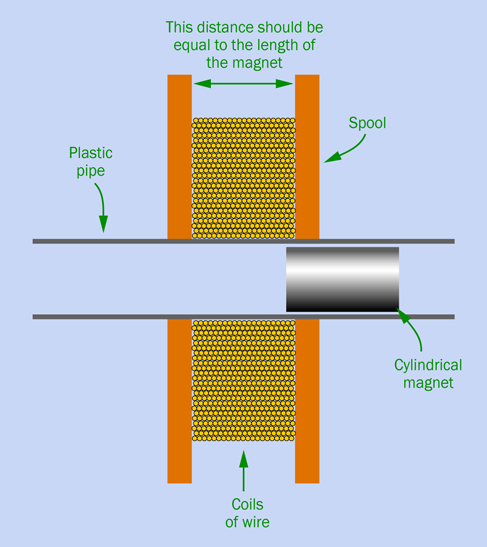
Figure 5-19. Setup for generating just enough power to light an LED.
You took all that trouble, and you got less than a volt?
Ah, but your meter is averaging the current. Each pulse is probably peaking at a higher voltage.
Disconnect your test leads from the meter, and attach them to a low-current LED. Clamp the LED so that it doesn’t jostle around. Now when you move the magnet vigorously, I think you will see the LED flicker. If it doesn’t, reverse the orientation of the magnet in the tube and try again. You really need a low-current LED to make this work.
Optional Extensions
If you are willing to spend a little more money, you can get much more impressive results.
First, use a bigger magnet. I get excellent results from one that is 2” long and 5/8” in diameter. Of course, you’ll need a larger diameter of PVC pipe to accommodate the magnet.
Second, buy a spool of proper magnet wire. I used about 500 feet of 26-gauge wire. It’s easy to buy online; there are dozens of suppliers.
If you’re fortunate, your magnet wire will be supplied on a plastic spool with a hole in the middle just a little bit bigger than the diameter of your magnet. And, better still, the spool of magnet wire will allow you access to the “tail” of the wire sticking out in the center of the spool, as shown circled in red in Figure 5-20.

Figure 5-20. A spool of magnet wire with the inside end accessible, circled in red.
To remove the thin film of insulation from the ends of the magnet wire, you can scrape them very gently with a knife blade, or rub them with fine sandpaper. Check with a magnifying glass to make sure that some insulation has been removed. You can also apply your meter to check the resistance, which should be less than 100 ohms.
Now you can attach an LED to each end of the magnet wire on the spool, and generate voltage by pushing your magnet in and out of the center of the spool, as shown in Figure 5-21.
If the spool is the wrong size, or if the tail of the wire isn’t accessible, you’ll just have to rewind the wire from one spool to another. Suppose you have 500 feet; that will entail rewinding about 2,000 turns. If you can make four turns per second, you’ll require 500 seconds—a little less than 10 minutes, which I think is tolerable.
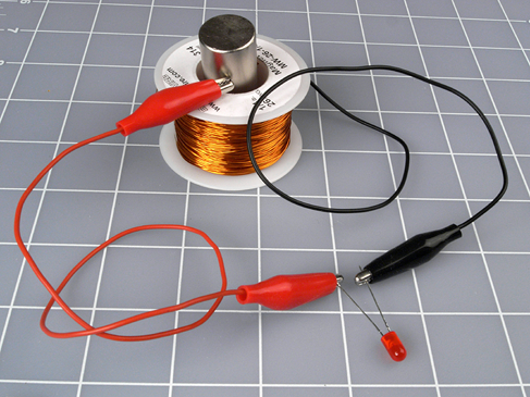
Figure 5-21. Ready for power generation, on a rather small scale.
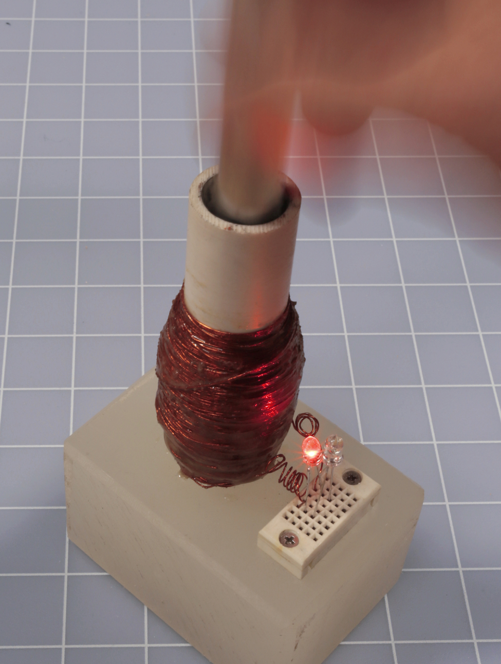
Figure 5-22. Demonstration device capable of dazzling results.
Figure 5-22 shows a larger-scale device that I built for demonstration purposes. The coil of magnet wire is coated with epoxy glue, so that it won’t unravel, and I mounted the pipe in a block of plastic that holds it securely. My neodymium magnet attaches itself to a steel screw in to the end of an aluminum rod, also visible in the photograph.
I added two high-intensity LEDs to the coil, with their polarity in opposite directions. When the magnet shuttles up and down, the LEDs light up the whole room. Also, their opposite polarity shows that voltage travels through the coil in one direction on the upstroke, and in the other direction on the downstroke. See Figure 5-23.
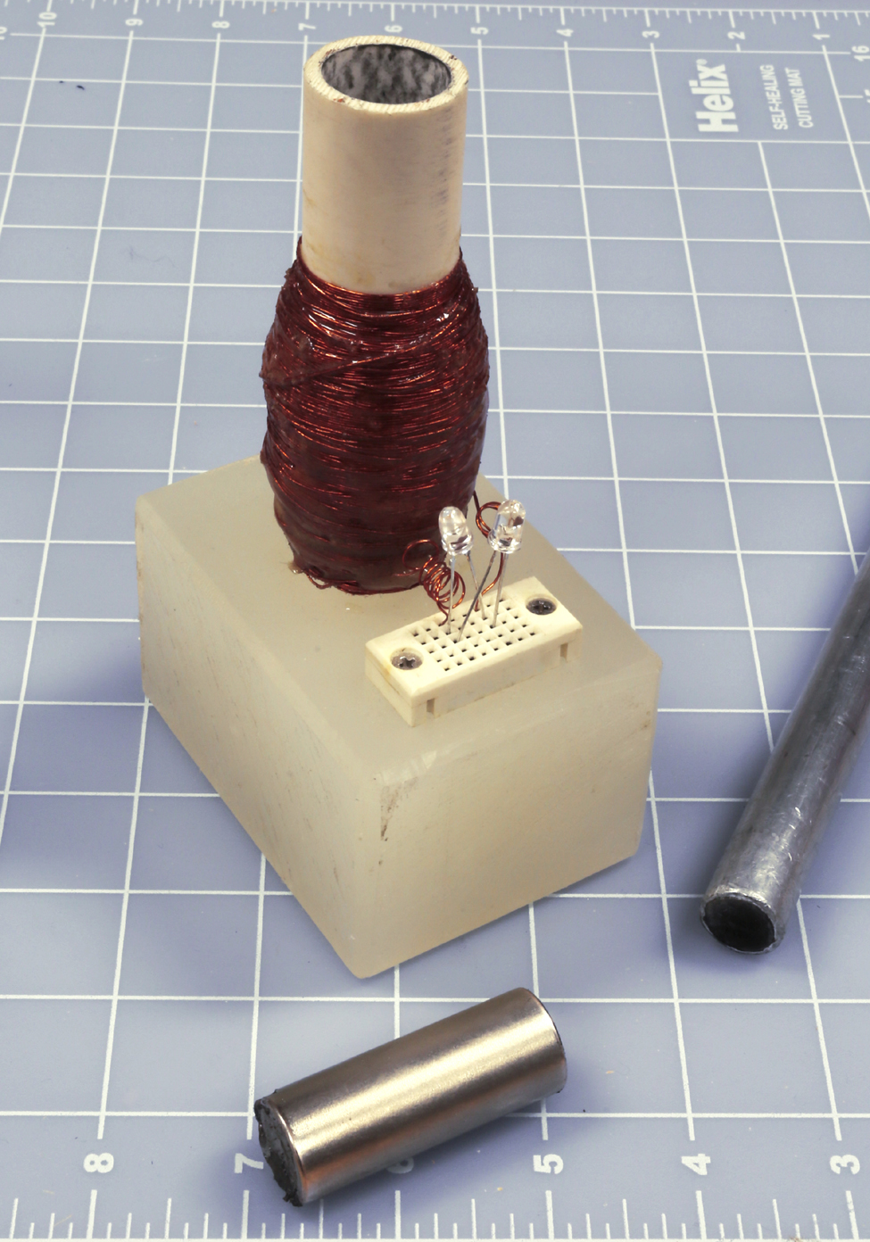
Figure 5-23. The LED generator in action.
Caution: Blood Blisters and Dead Media
Beware of the spooky capabilities of neodymium.
Neodymium magnets are breakable. They’re brittle and can shatter if they slam against a piece of magnetic metal (or another magnet). For this reason, many manufacturers advise you to wear eye protection.
You can easily pinch your skin and get blood blisters (or worse). Because a magnet pulls with increasing force as the distance between it and another object gets smaller, it closes the final gap very suddenly and powerfully. Ouch!
Magnets never sleep. In the world of electronics, we tend to assume that if something is switched off, we don’t have to worry about it. Magnets don’t work that way. They are always sensing the world around them, and if they notice a magnetic object, they want it, now. Results may be unpleasant, especially if the object has sharp edges and your hands are in the way. When using a magnet, create a clear area on a nonmagnetic surface, and watch out for magnetic objects underneath the surface. For example, my magnet sensed a steel screw embedded in the underside of a kitchen countertop, and slammed itself into contact with the countertop unexpectedly.
It’s hard to take this seriously until it happens to you. But, seriously, neodymium magnets don’t fool around. Proceed with caution.
Also, remember that magnets create magnets. When a magnetic field passes across an iron or steel object, the object picks up some magnetism of its own. If you wear a watch, be careful not to magnetize it. If you use a smartphone, keep it away from magnets. Likewise, any computer or disk drive is vulnerable. The magnetic stripe on a credit card is easily erased. Also keep magnets well away from TV screens and video monitors (especially cathode-ray tubes). Last but not least, powerful magnets can interfere with the normal operation of cardiac pacemakers.
Charging a Capacitor
Here’s another thing to try. Disconnect the LED from whatever coil of wire you created, and connect a 1,000µF electrolytic capacitor in series with a 1N4001 signal diode, as shown in Figure 5-24. Attach your meter, measuring DC volts (not AC, this time), across the capacitor.
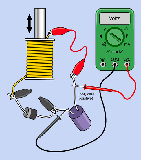
Figure 5-24. A diode enables you to accumulate voltage from your coil in a capacitor.
If your meter has a manual setting for its range, set it to at least 2VDC. Make sure the positive (unmarked) side of the diode is attached to the negative (marked) side of the capacitor, so that positive voltage will pass through the capacitor and then through the diode.
Now move the magnet vigorously up and down in the coil. The meter should show that the capacitor is accumulating charge. When you stop moving the magnet, the voltage reading may decline very slowly, mostly because the capacitor discharges itself through the internal resistance of your meter.
This experiment is more important than it looks. Bear in mind that when you push the magnet into the coil, it induces current in one direction, and when you pull it back out again, it induces current in the opposite direction. You are actually generating alternating current.
The diode only allows current to flow one way through the circuit. It blocks the opposite flow, which is how the capacitor accumulates its charge. If you jump to the conclusion that diodes can be used to convert alternating current to direct current, you’re absolutely correct. We say that the diode is “rectifying” the AC power.
Next: Audio
Experiment 25 showed that voltage can create a magnet. Experiment 26 has shown that a magnet can create voltage. We’re now ready to apply these concepts to the detection and reproduction of sound.
Experiment 27: Loudspeaker Destruction
You saw that electricity running through a coil can create enough magnetic force to pull a small metallic object toward it. What if the coil is very light, and the object is heavier? In that case, the coil can be pulled toward the object. This principle is at the heart of a loudspeaker.
To understand how a loudspeaker works, there’s really no better way than to disassemble it. Maybe you’d prefer not to spend a few dollars on this destructive but educational process—in which case, you might consider picking up a piece of nonfunctional audio equipment at a yard sale, and pulling a loudspeaker out of that. Or simply take a look at my photographs illustrating the process step by step.
What You Will Need
-
Cheapest possible loudspeaker, 2” minimum (1)
-
Utility knife (1)
Procedure
Figure 5-25 shows a small loudspeaker seen from the rear. A magnet is hidden in the sealed cylindrical section.
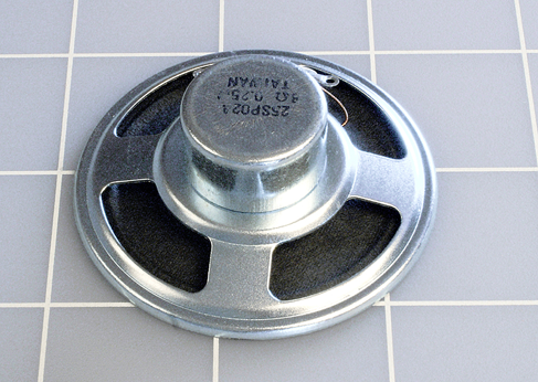
Figure 5-25. The back of a small loudspeaker.
Turn the loudspeaker face-up, as shown in Figure 5-26. Cut around the perimeter of its cone with a sharp utility knife or X-Acto blade. Then cut around the circular center and remove the O-shaped circle of black paper that you’ve created.
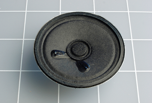
Figure 5-26. A two-inch loudspeaker ready for its fate.
The unconed speaker is shown in Figure 5-27. The yellow weave at the center is the flexible section that normally allows the cone to move in and out, while preventing it from deviating from side to side.

Figure 5-27. The loudspeaker with its cone removed.
Cut around the outside edge of the yellow weave, and you should be able to pull up a hidden paper cylinder, which has a copper coil wound around it, as shown in Figure 5-28. In the photograph, I’ve turned it over so that it is easily visible.

Figure 5-28. The copper coil is normally hidden inside the groove of the magnet, below.
The two ends of this copper coil normally receive power through flexible wires from two terminals at the back of the speaker. When the coil sits in the groove visible in the magnet, the coil reacts to voltage fluctuations by exerting an up-and-down force in reaction to the magnetic field. This vibrates the cone of the loudspeaker and creates sound waves.
Large loudspeakers in your stereo system work exactly the same way. They just have bigger magnets and coils that can handle more power (typically, as much as 100 watts).
Whenever I open up a small component like this, I’m impressed by the precision and delicacy of its parts, and the way it can be mass-produced for such a low cost. I imagine how astonished Faraday, Henry and the other pioneers of electrical research would be, if they could see the components that we take for granted today. Henry spent days winding coils by hand to create electromagnets that were far less efficient than this cheap little loudspeaker.
Background: Origins of Loudspeakers
As I mentioned at the beginning of this experiment, a coil will move if its magnetic field interacts with a heavy or fixed object. If the object is a permanent magnet, the coil will interact with it more strongly, creating more vigorous motion. This is how a loudspeaker works.
The idea was introduced in 1874 by Ernst Siemens, a prolific German inventor. (He also built the world’s first electrically powered elevator in 1880.) Today, Siemens AG is one of the largest electronics companies in the world.
When Alexander Graham Bell patented the telephone in 1876, he used Siemens’ concept to create audible frequencies in the earpiece. From that point on, sound-reproduction devices gradually increased in quality and power, until Chester Rice and Edward Kellogg at General Electric published a paper in 1925 establishing basic principles that are still used in loudspeaker design today.
At sites such as Radiola Guy, you’ll find photographs of very beautiful early loudspeakers, which used a horn design to maximize efficiency, as shown in Figure 5-29. As sound amplifiers became more powerful, speaker efficiency became less important compared with quality reproduction and low manufacturing costs. Today’s loudspeakers convert only about 1% of electrical energy into acoustical energy.

Figure 5-29. This beautiful Amplion AR-114x illustrates the efforts of early designers to maximize efficiency in an era when the power of audio amplifiers was very limited. Photos by “Sonny, the RadiolaGuy.” Many early speakers are illustrated at http://www.radiolaguy.com. Some are for sale.
Theory: Sound, Slectricity, and Sound
Time now to establish a more specific idea of how sound is transformed into electricity and back into sound again.
Suppose someone bangs a gong with a stick, as shown in Figure 5-30. The flat metal face of the gong vibrates in and out, creating pressure waves that the human ear perceives as sound. Each wave of high air pressure is followed by a trough of lower air pressure, and the wavelength of the sound is the distance (usually ranging from meters to millimeters) between one peak of pressure and the next.

Figure 5-30. Striking a going makes its flat surface vibrate. The vibrations create waves of pressure in the air.
The frequency of the sound is the number of waves per second, usually expressed as hertz.
Suppose we put a very sensitive little membrane of thin plastic in the path of the pressure waves. The plastic will flutter in response to the waves, like a leaf fluttering in the wind. Suppose we attach a tiny coil of very thin wire to the back of the membrane so that it moves with the membrane. And let’s position a stationary magnet inside the coil of wire. This configuration is like a tiny, ultra-sensitive loudspeaker, except that instead of electricity producing sound, the sound will produce electricity. Pressure waves make the membrane oscillate along the axis of the magnet, and the magnetic field creates a fluctuating voltage in the wire. The principle is illustrated in Figure 5-31.
This is known as a moving-coil microphone. There are other ways to build a microphone, but this is the configuration that is easiest to understand. Of course, the voltage that it generates is very small, but we can amplify it using a transistor, or a series of transistors, as suggested in Figure 5-32.
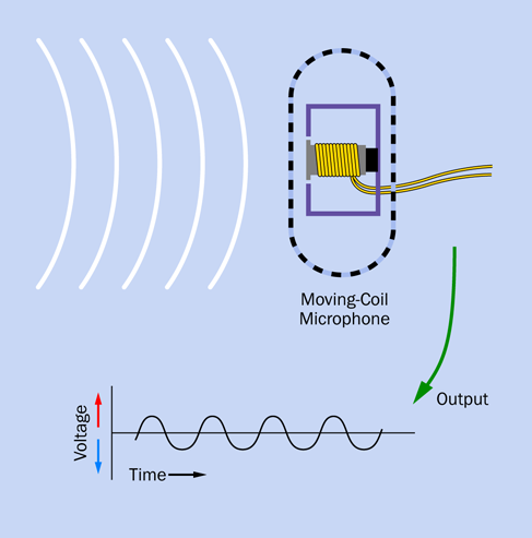
Figure 5-31. Sound waves entering a moving-coil microphone make a membrane vibrate. The membrane is attached to a coil on a sleeve around a magnet. Motion of the coil induces small currents.
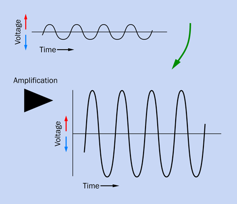
Figure 5-32. Tiny signals from the microphone pass through an amplifier, which enlarges their amplitude while retaining their frequency and the shape of their waveform.
Then we can feed the output through the coil around the neck of a loudspeaker, and the loudspeaker will recreate the pressure waves in the air, as shown in Figure 5-33.

Figure 5-33. The amplified electrical signal is passed through a coil around the neck of a loudspeaker cone. The magnetic field induced by the current causes the cone to vibrate, reproducing the original sound.
Somewhere along the way, we may want to record the sound and then replay it. But the principle remains the same. The hard part is designing the microphone, the amplifier, and the loudspeaker so that they reproduce the waveforms accurately at each step. It’s a significant challenge, which is why accurate sound reproduction can be elusive.
Experiment 28: Making a Coil React
You’ve seen that when you pass current through a coil, the current creates a magnetic field. When you disconnect the current, what happens to the field that it created?
The energy in the field is converted back into a brief pulse of electricity. We say that this happens when the field collapses.
This experiment will enable you to see it for yourself.
What You Will Need
-
Breadboard, hookup wire, wire cutters, wire strippers, multimeter
-
Low-current LEDs (2)
-
Hookup wire, 22 gauge (26 gauge preferred), 100 feet (1 spool)
-
Resistor, 47 ohms (1)
-
Capacitor, 1,000 µF or larger (1)
-
Tactile switch (1)
Procedure
Take a look at the schematic in Figure 5-34. The breadboarded version is shown in Figure 5-35. For the coil, you can use a spool of 100 feet of 22-gauge hookup wire. Alternatively, if you created your own coil of 200 feet of wire in Experiment 26, you can use that; and if you splurged on a spool of magnet wire, that will be even better.

Figure 5-34. A simple circuit to demonstrate the self-inductance of a coil.
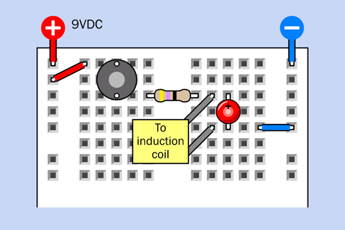
Figure 5-35. Breadboarded version of the self-inductance experiment.
When you look at the schematic, it doesn’t seem to make much sense. The 47-ohm resistor seems too small to protect the LED—but why should the LED light up at all, when the electricity can go around it through the coil?
Now test the circuit, and I think you’ll be surprised. Each time you press the button, the LED blinks briefly. Can you imagine why that should be?
Try adding a second LED, the other way up, as in Figure 5-36 and Figure 5-37. Press the button again, and the first LED flashes, as before. But now when you release the button, the second LED flashes.
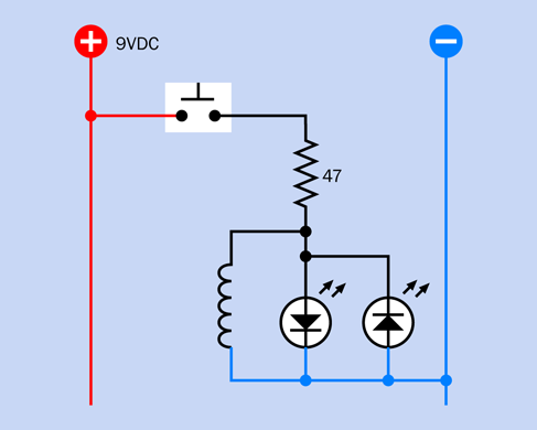
Figure 5-36. One LED flashes when a magnetic field is created; the other flashes when the field collapses.

Figure 5-37. Breadboarded version of the two-LED demonstration circuit.
A Collapsing Field
Here’s what happened during this experiment. At first, the coil required a brief amount of time to build up a magnetic field. This took a moment, and during that moment the coil blocked some of the flow of current. As a result, some of the current detoured through the first LED. Once the magnetic field was established, current flowed through the coil more normally.
This response of the coil is known as self-inductance. Sometimes people use the term inductive reactance, or just reactance, but since self-inductance is the correct term, I’ll be using it here.
When you disconnected the power, the magnetic field collapsed, and the energy from the field was converted back into electricity in a short, brief pulse. This caused the second LED to flash when you let go of the button.
Naturally, different sizes of coil store and release different amounts of energy.
Perhaps you remember in Experiment 15, I advised you to tie a diode across the coil of a relay to absorb the surge that occurs when a relay coil is switched on and off. You have now seen this effect for yourself.
Resistors, Capacitors, and Coils
The three primary types of passive components in electronics are resistors, capacitors, and coils. We can now list and compare their properties.
A resistor constrains current flow, and drops voltage.
A capacitor allows a pulse of current to flow initially, but blocks direct current.
A coil (often referred to as an inductor) blocks DC current initially, but allows a continuing flow of direct current.
In the circuit that I just showed you, I didn’t use a higher-value resistor because I knew the coil would allow only a very brief pulse. The blinking LEDs would have been less easily visible if I had used a more usual 330-ohm or 470-ohm resistor.
Don’t try to run the circuit without the coil of wire included. You will quickly burn out one or both of the LEDs. The coil may look as if it isn’t doing anything, but it is.
Here’s one last variation on this experiment, to test your memory and understanding of electrical fundamentals. Build a new circuit shown in Figure 5-38 and Figure 5-39 using a 1,000µF capacitor instead of a coil (be careful to get its polarity the right way around, with the positive lead at the top.) Also, use a 470-ohm resistor, because the coil isn’t there to block and divert current anymore.
First hold down button B for a second or two to make sure that the capacitor is discharged. Now, what will you see when you press button A? Maybe you can guess. Remember, a capacitor will pass an initial pulse of electricity. Consequently, the bottom LED lights up—and then gradually fades out, because the capacitor accumulates a positive charge on its upper plate and a negative charge on its lower plate. As this occurs, the potential across the lower LED diminishes to zero.

Figure 5-38. In many ways, the behavior of a capacitor is opposite to the behavior of a coil.

Figure 5-39. Breadboarded version of the capacitor demo.
The capacitor is now charged. Press the right-hand button, and the capacitor discharges through the upper LED. You can see this as the equivalent of the experiment in Figure 5-37, but using a capacitor instead of a coil.
Capacitors and inductors both store power. You were able to see this more obviously with the capacitor, because a high-value capacitor is much smaller than a high-value coil.
Theory: Alternating Current Concepts
Here’s a simple thought experiment. Suppose you set up a 555 timer to send a stream of pulses through a coil. This will be a primitive form of alternating current.
Will the self-inductance of the coil interfere with the stream of pulses? That will depend on how long each pulse is, and how much inductance the coil has. If the frequency of pulses is just right, the self-inductance of the coil will last just long enough to block each pulse. Then the coil will recover in time to block the next one. In conjunction with a resistor (or just the resistance of the loudspeaker) a coil can suppress some frequencies while allowing others to pass through.
If you have a stereo system that uses a small speaker to reproduce high frequencies and a large speaker to reproduce low frequencies, almost certainly there is a coil somewhere in the speaker cabinet, stopping the higher frequencies from reaching the large speaker.
What happens if you substitute a capacitor for a coil? If the AC pulses are long relative to the value of the capacitor, it will tend to block them. But if the pulses are shorter, the capacitor can charge and discharge in rhythm with the pulses, and will allow them through.
I don’t have space in this book to get deeply into alternating current. It’s a vast and complicated field where electricity behaves in strange and wonderful ways, and the mathematics that describe it can become quite challenging, involving differential equations and imaginary numbers. (What is an imaginary number? The most obvious example is the square root of minus-one. How can that exist? Well—it can’t, which is why we say that it’s imaginary. Yet it crops up in electrical theory. If that sounds interesting, you may want to check it out.)
But I haven’t finished with coils yet. The next experiment will demonstrate the audio effects that I just described above.
Experiment 29: Filtering Frequencies
In this experiment, you’ll change the sound of sound. Using coils and capacitors, you can filter sections of the audible spectrum to create a rich variety of effects.
What You Will Need
-
Breadboard, hookup wire, wire cutters, wire strippers, test leads, multimeter
-
9-volt power supply (battery or AC adapter)
-
Loudspeaker, 8 ohms impedance, minimum 4 inches diameter (1)
-
Audio amplifier chip, LM386 (1)
-
22-gauge hookup wire, 100 feet
-
Small plastic storage bin as a loudspeaker enclosure (1)
-
555 timer (1)
-
Resistors, 10K (2)
-
Capacitors: 0.01µF (3), 2.2µF (1), 100µF (1), 220µF (3)
-
Trimmer potentiometers: 10K (1), 1M (1)
-
SPDT slide switches (4)
-
Tactile switch (1)
A Home for Your Speaker
The little speaker that I recommended for previous projects was adequate when all you needed was a few beeps, but small speakers have a limited capability to reproduce bass notes. Since I want you to be able to hear how electronic components can affect those notes, it’s time to consider a larger speaker, such as the one in Figure 5-40, which has a cone four inches in diameter.

Figure 5-40. A loudspeaker that would be suitable for this project.
Bearing in mind my previous comments on the need to suppress out-of-phase sound waves from the back of the speaker, you’ll need a box to contain it. The box will also boost the sound by resonating, in the same way that the body of an acoustic guitar resonates with the vibrations of its strings.
If you have time to make a plywood box, that would be ideal, but the simplest and cheapest enclosure is probably a plastic storage bin with a snap-on lid. Figure 5-41 shows the speaker bolted into the bottom of a bin. Drilling holes neatly in thin plastic is quite a challenge, and—well, I didn’t try too hard.
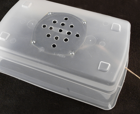
Figure 5-41. A resonant enclosure is necessary if you want to hear some bass (lower frequencies) from your speaker. A cheap plastic storage bin is sufficient for demo purposes.
To improve the attributes of the plastic bin, you can put some soft, heavy fabric inside it before you snap the lid on. A hand towel or some socks should be sufficient to absorb some of the vibration.
A Single Chip
Back in the 1950s, you needed vacuum tubes, transformers, and other power-hungry, heavyweight components to build an audio amplifier. Today, you can buy a chip for about $1 that will do the job, if you add a few capacitors around it, and a volume control.
One of the simplest, cheapest, and easiest to use is the LM386, which is available from multiple manufacturers, each of which prefaces or appends some extra identifying letters and numbers to it. The LM386N-1, LM386N, and LM386M-1 are all basically the same for our purposes. Just make sure you buy the through-hole version, not the surface-mount version. Pinouts for this amplifier are shown in Figure 5-42.
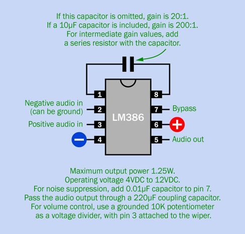
Figure 5-42. Pinouts for the LM386 single-chip amplifier.
This little chip works with a power supply ranging from 4VDC to 12VDC, and although it is rated for just 1.25 watts, you’ll be surprised how loud it can sound. It has a nominal amplification ratio of 20:1.
Test, 1-2-3
For testing purposes, I want a source of frequencies covering a large range of the audible spectrum. A simple way to achieve this is with a 555 timer. The schematic in Figure 5-43 shows the timer at the top, with component values that can deliver a range from around 70Hz to 5KHz when you twiddle the 1M trimmer potentiometer. Unfortunately you won’t hear this as a linear response, by which I mean that a small rotation of the trimmer will have a much greater audible effect on high frequencies than on low frequences. But, it will be good enough for demo purposes, and the lower frequencies provide a more dramatic demo of audio filtering anyway.
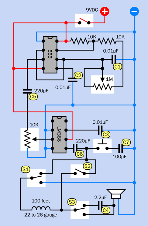
Figure 5-43. A basic audio experimentation circuit.
The breadboarded version of the circuit is shown in Figure 5-44 and the component values are shown in Figure 5-45.
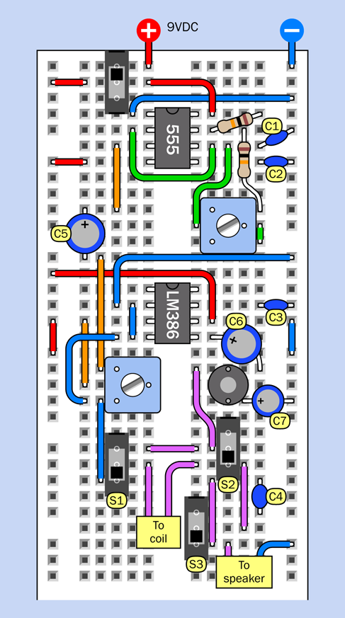
Figure 5-44. Breadboarded version of the audio experimentation circuit.

Figure 5-45. Component values in the audio experimentation circuit.
When you build this circuit, I have to warn you that amplifiers are sensitive to all electrical fluctuations, not just the ones you want to hear. Any electrical interference will be reproduced as a mess of scratchy, buzzing sounds, and this problem will be much worse if you use unnecessarily long pieces of wire to connect components.
The kind of jumper wires with little plugs on the end are especially undesirable in an amplifier circuit, as they behave like radio antennas. I have tried to limit the lengths of all the wires in the breadboard layout shown in Figure 5-44, and I encourage you to do the same. The only locations where wire length doesn’t matter too much are on the power-output side of the chip, where you need to attach wires to your loudspeaker and to a coil.
For the coil, magnet wire of 22 gauge or thinner is ideal, but you will get some audible results from a 100-foot spool of 22-gauge hookup wire, and the 200 feet of hookup wire that I suggested in the previous experiment would be better.
Now, before powering up your breadboard, please pay attention to the three slide switches near the bottom of the circuit, and make sure that all of them are in the “down” position. In other words, slide them toward the bottom of the breadboard. Also turn the two trimmer potentiometers about halfway through their range.
You can power this project with an AC adapter or a 9-volt battery, with no regulation necessary. However, if you use an adapter, it may introduce some hum into the circuit. You can reduce this by placing a capacitor of 1,000µF or more between the two buses of the breadboard. If you use a battery, the power consumption of the amplifier will limit battery life to two or three hours, and some of the sound filters will pull down the voltage slightly, affecting the audio frequency created by the 555 timer.
As soon as you switch on the power, you should hear a tone. If you don’t, your first troubleshooting strategy should be to disconnect the upper lead of the 220µF capacitor from the output pin of the 555 timer, and touch your speaker wires very briefly between that pin and the negative bus. If you don’t hear anything, you made a wiring error around the timer. If you do hear something, then your error is related to the LM386 amplifier chip.
Make sure you connected power to the correct pins of the LM386. The positive and negative supply pins are not in the same positions as on logic chips.
Still no sound? Detach the top end of the short vertical piece of blue wire above the 10K trimmer. Touch the end of this piece of wire with your finger, and you should hear some whistling and buzzing sounds, because this is attached to the input pin of the amplifier (pin 4). Still nothing? Try attaching your speaker between the negative side of capacitor C6, and the negative power supply bus. C6 is a coupling capacitor connecting you directly with the output pin of the LM386.
If none of these attempts is successful, you’ll have to go around the circuit with your meter, checking voltages.
Adventures in Audio
Assuming that your circuit is now up and running, I’ll explain the functions of the components before I suggest some things to try. I’m going to refer to the labels that I applied to components in the breadboard layout shown in Figure 5-44.
Capacitor C1 sets the frequency of the timer, in conjunction with the 1M trimmer. Just in case you want to hear a sound higher in pitch than 5KHz, you can substitute a 0.0068µF (6.8nF) capacitor.
C5 is a coupling capacitor. It has a large value so that it will be transparent to a wide range of frequencies. Its purpose is to block DC from the 555 timer, because you only want to amplify the fluctuations, not the basic voltage.
Capacitor C6 is another coupling capacitor, protecting your loudspeaker from the DC coming out of the amplifier.
Capacitor C7 couples the amplifier output to negative ground when you press the button beside it. The value of C7 is chosen so that it takes away the higher frequencies, shunting them to ground. Without those frequencies, the sound that goes to the loudspeaker sounds more mellow.
Capacitor C4 is switched in and out of the circuit by slide switch S3. When the slide is up, sound from the 555 passes through C4 on its way to the amplifier. Because C4 has a small value, it blocks low frequencies, leaving you with a thin, tinny sound.
The complicated part of the circuit relates to the coil. I wanted you to hear the difference when a coil is connected in parallel with the loudspeaker, and when it is in series with the loudspeaker. Switches S1 and S2 give you those options, as shown in Figure 5-46 and Figure 5-47. When the coil is in parallel with the speaker, this is sometimes described as bypassing the speaker.

Figure 5-46. Switches S1 and S2 (identified in the breadboard diagram for the circuit) allow you to feed audio to the speaker in parallel with an external coil, or in series with it.
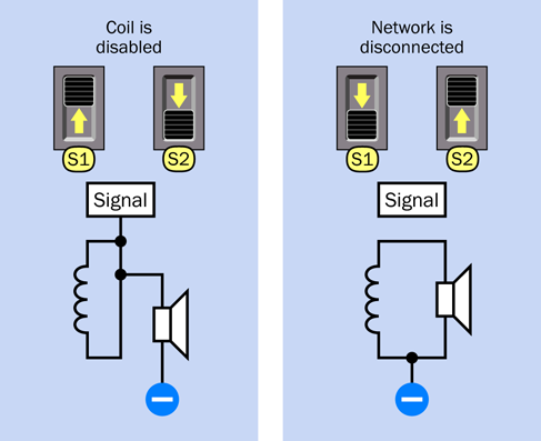
Figure 5-47. Two other configurations of S1 and S2 allow you either to bypass the coil, or mute the output from the amplifier.
You have quite a lot to play with here, especially bearing in mind that you can adjust the frequency and volume of the sound while you test the various filters. You can also test the effect of using two filters simultaneously. For instance, press the button to activate the bypass capacitor C7, which cuts the high frequencies, and switch C4 into the circuit at the same time, to cut the low frequencies. Now you have a bandpass filter, so called because you are passing just a narrow band of frequencies in the midrange.
The trimmer at bottom-left functions as a volume control, but you’ll find that it only works properly in the middle part of its range. If you push it too high or too low, the circuit starts oscillating. This is a problem with amplifier circuits. The solution tends to involve adding small and large capacitors in various locations. I decided not to bother, because the midrange of the trimmer is usable.
The capacitors and coils in this circuit are all operating on a passive basis. They block some frequencies, but they don’t boost any frequencies. A more sophisticated audio filtering system uses transistors to provide active filtering, but requires a lot more electronics.
Theory: Waveforms
If you blow across the top of a bottle, the mellow sound that you hear is caused by the air vibrating inside the bottle. If you could make a graph of the pressure waves, they would have a rounded profile.
If you could slow down time and draw a graph of the alternating voltage in any power outlet in your house, it would have the same profile.
If you could measure the speed of a pendulum swinging slowly to and fro in a vacuum, and draw a graph of the speed relative to time, once again it would have the same profile.
That profile is a sine wave, so called because you can derive it from basic trigonometry. In a right-angled triangle, suppose one of the sides adjacent to the right angle is called “a.” If you divide the length of “a” by the length of the sloping side of the triangle (the hypoteneuse), the result is the sine of the angle opposite side “a.”
To make this simpler, imagine a ball on a string rotating around a center point, as shown in Figure 5-48. Ignore the force of gravity, the resistance of air, and other annoying variables. Just measure the vertical height of the ball and divide it by the length of the string, at regular instants of time, as the ball moves around the circular path at a constant speed. Plot the result as a graph, and there’s your sine wave, shown in Figure 5-49. Note that when the ball circles below its horizontal starting line, we consider its distance negative, so the sine wave becomes negative, too.
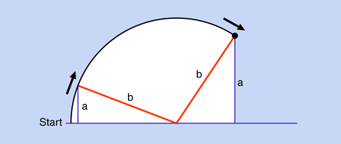
Figure 5-48. You can draw a sine wave by beginning with simple geometry.

Figure 5-49. An audio sine wave is generated by any instrument that uses a vibrating column of air—such as a flute. It is a gentle, harmonious sound.
Why should this particular curve turn up in so many places and so many ways in nature? There are reasons for this rooted in physics, but I’ll leave you to dig into that topic if it interests you. Getting back to the subject of audio reproduction, what matters is this:
-
The static pressure in the air around you is called ambient pressure. It results from air being pulled down by the force of gravity. (Yes, air does have weight.)
-
Almost any sound consists of a wave that is higher than ambient pressure, followed by a wave that is lower than ambient pressure—just like waves in the ocean.
-
We can represent the higher and lower waves of pressure by voltages that are relatively high and relatively low, which is why I used the red and blue background in Figure 5-49.
-
Any sound can be broken down into a mixture of sine waves of varying frequency and amplitude.
Or, conversely:
-
If you put together the right mix of audio sine waves, you can create any sound at all.
Suppose that there are two sounds playing simultaneously. Figure 5-50 shows one sound as a purple curve and the other as a green curve. When the two sounds travel either as pressure waves through air or as alternating electric currents through a wire, their amplitudes are added together to make the more complex curve, which is shown in black. Now try to imagine dozens or even hundreds of different frequencies being added together, and you have an idea of the complex waveform of a piece of music.
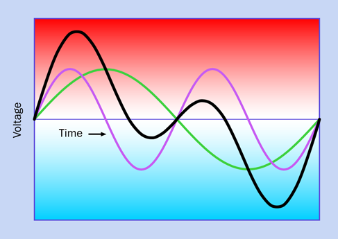
Figure 5-50. When two sine waves are generated at the same time (for instance, by two musicians, each playing a flute), the combined sound creates a compound curve. The purple sine wave is twice the frequency of the green sine wave. The compound curve (black line) is the sum of the distances of the sine waves from the baseline of the graph.
An astable 555 timer circuit creates a square wave. This is because the output from the timer switches abruptly from low to high and back again. The result is shown in Figure 5-51. A sine wave sounds gentle and melodious, as it varies smoothly. A square wave tends to sound harsh, and has a “buzz” to it. That buzz is really composed of harmonics, meaning frequencies that are two or more times the basic frequency.
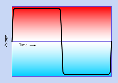
Figure 5-51. The square wave that you might obtain from a source such as a 555 timer, which switches its output abruptly on and off.
Because a square wave contains high-frequency harmonics, it’s a good choice for testing audio filters. A low-pass filter, which only allows lower frequencies, will remove the buzz by rounding off the corners of the square wave.
Mangling Some Music
You may be wondering, if the LM386 is an audio amplifier, can it amplify music? Yes, and in fact, that’s what it is designed to do. You can test this for yourself using any audio device with a headphone output.
Bear in mind that the LM386 is only a mono amplifier, so you won’t be able to hear both audio channels from your music player. To obtain just one of them, use a cable with a miniature audio jack at each end. Cut off one of them, strip the insulation from the wire, and you will find a mesh of fine wires that are the shielding in the cable, to be connected with negative ground. Inside the shielding will be two conductors, carrying the signals for the left channel and the right channel. Snip off one of them (it doesn’t matter which one), and throw it away—but don’t allow the conductor in the residual stub of wire to short-circuit with the shielding.
Strip insulation from the remaining conductor. The wires inside are very thin, and you will be able to deal with them more easily in this experiment if you add a little solder. The desired result is shown in Figure 5-52.
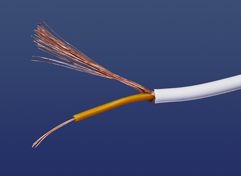
Figure 5-52. An audio cable stripped to expose its shielding and one conductor. The shielding connects with negative ground.
Make sure the power to your amplifier circuit is off, and push all the slide switches to the down positions. Remove the orange piece of wire that connects pin 3 of the 555 timer with the 220µF capacitor below it. You are taking the 555 timer out of the circuit, and using the positive end of capacitor C6 as your input point.
Use one of your alligator test leads to grab the positive capacitor lead, and attach the other end of the test lead to the audio conductor in your cable. Use another test lead to connect the shielding from the cable to negative ground in your circuit. It’s essential that your music player must share negative ground with your amplifier circuit.
Switch on your circuit, then switch on your music player, and you should hear music. If it’s too loud and distorted, you may need to insert a 1K or 10K resistor between the audio wire from the music player and the positive end of the capacitor.
Once you have the volume right, you can play with your high-pass and low-pass filters to see how they affect the music. They won’t make it sound good, but they will make it sound different.
Background: Crossover Networks
In a traditional audio system, each speaker cabinet contains two drivers—one of them a small speaker called a tweeter, which reproduces high frequencies, the other a large speaker known as a woofer, which reproduces low frequencies. (Modern systems often remove the woofer and place it in a separate box of its own that can be positioned almost anywhere, because the human ear has difficulty sensing the direction of low-frequency sounds. In this system, the woofer may be referred to as a subwoofer, because it is capable of reproducing very low frequencies.)
Audio frequencies are divided between a tweeter and a woofer by filtering them, so that the tweeter doesn’t try to deal with any low frequencies, and the woofer is protected from high frequencies. The circuit that takes care of this is called a “crossover network,” and truly hardcore audiophiles have been known to make their own (especially for use in car systems) to go with speakers of their choice in cabinets that they design and build themselves.
If you want to make a crossover network, you should use high-quality polyester capacitors (which have no polarity, last longer than electrolytics, and are better made) and a coil that has the right number of turns of wire and is the right size, to cut high frequencies at the appropriate point. Figure 5-53 shows a polyester capacitor, while Figure 5-54 shows an audio crossover coil that I bought on eBay for $6. I was curious to find out what was inside it, so I took it apart.
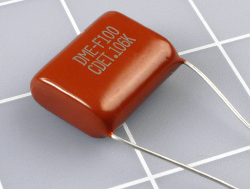
Figure 5-53. Some nonelectrolytic capacitors have no polarity, such as this high-quality polyester film capacitor.
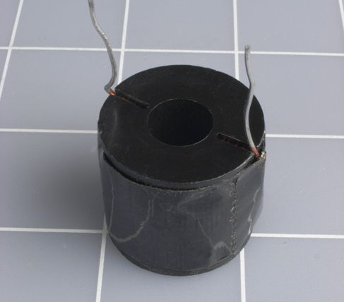
Figure 5-54. What exotic components may we find inside this high-end audio component?
First I peeled away the black vinyl tape that enclosed the coil. Inside was some typical magnet wire—copper wire thinly coated with shellac or semitransparent plastic, as shown in Figure 5-55. I unwound the wire, and as I did so, I counted the number of turns.
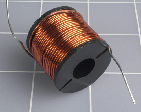
Figure 5-55. The black tape is removed, revealing a coil of magnet wire.
Figure 5-56 shows the wire and the spool that it was wound around.

Figure 5-56. The audio crossover coil consists of a plastic spool and some wire. Nothing more.
So here’s the specification for this particular coil in an audio crossover network. Forty feet of 20-gauge copper magnet wire, wrapped in 200 turns around a small plastic spool.
Conclusion: there’s a lot of mystique attached to audio components. They are frequently overpriced, and you can make your own coil if you start with these parameters and adjust them to suit yourself.
Suppose you want to put some thumping bass speakers into your car. Could you build your own filter so that they only reproduce the low frequencies? Absolutely—you just need to wind a coil, adding more turns until it cuts as much of the high frequencies as you choose. Just make sure the wire is heavy enough so that it won’t overheat when you push 100 or more audio watts through it.
Here’s another project to think about: a color organ. You can tap into the output from your stereo and use filters to divide audio frequencies into three sections, each of which drives a separate set of colored LEDs. The red LEDs will flash in response to bass tones, yellow LEDs in response to the midrange, and green LEDs in response to high frequencies (or whatever colors you prefer). You can put signal diodes in series with the LEDs to rectify the alternating current, and series resistors to limit the voltage across the LEDs to, say, 2.5 volts (when the music volume is turned all the way up). You’ll use your meter to check the current passing through each resistor, and multiply that number by the voltage drop across the resistor, to find the wattage that it’s handling, to make sure the resistor is capable of dissipating that much power without burning out.
Audio is a field offering all kinds of possibilities if you enjoy designing and building your own electronics.
Experiment 30: Make It Fuzzy
Let’s try one more variation on the circuit in Experiment 29. This will demonstrate another fundamental audio attribute: distortion.
What You Will Need
-
The breadboarded circuit from Experiment 29, plus:
-
2N2222 transistor (1)
-
Resistors: 330 ohms (1), 10K (1)
-
Capacitors: 1µF (2) and 10µF (1)
Making the Mods
The modifications to the circuit are very minor. You need to add a transistor, two resistors, and three capacitors. Figure 5-57 shows the new components at the top end of the breadboard, with the preexisting components grayed out.
Figure 5-58 shows the same components, and their values, in the relevant section of the schematic, with other components omitted.
The 2N2222 transistor overloads the input of the LM386, while the 1µF capacitors, C8 and C9, limit low frequencies to emphasize the fuzzy effect.
The purpose of C10 is to boost the LM386. This is a feature of the chip: if you add a capacitor between pin 1 and pin 8, the power of the amplifier can increase from 20:1 to 200:1.
Thus, in two separate ways this unfortunate little amplifier chip is being forced to do more than its designers intended. Naturally enough, it will complain about this cruel treatment.
Make the modifications, and switch on the power. The output previously had some buzz in it, because it was basically a square wave. But now if you experiment with the 10K trimmer and the 1M trimmer, you can make the output scream, Hendrix-style.
If the result is too extreme, you can remove the 330-ohm resistor and substitute one with a slightly higher value. And what exactly is going on here?
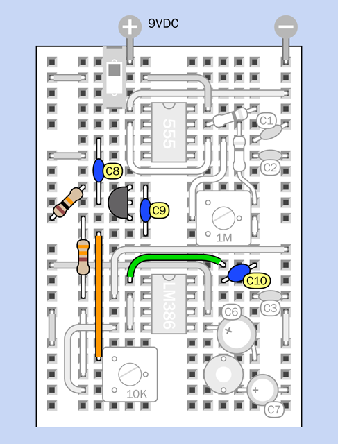
Figure 5-57. Modifications to the circuit from Experiment 29, to add more distortion.
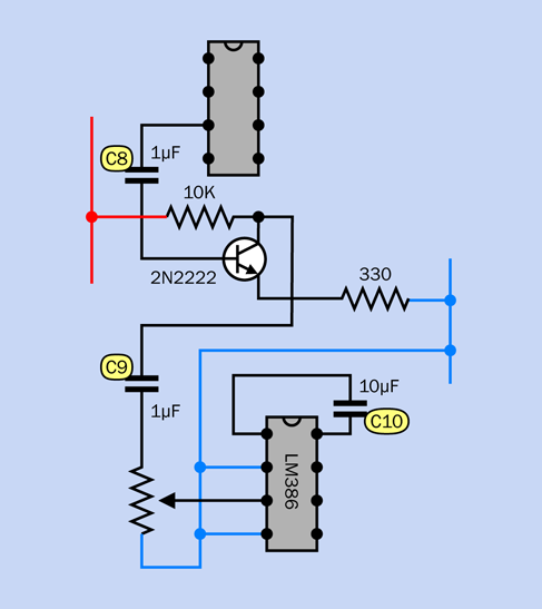
Figure 5-58. The additional components, with values.
Background: Clipping
In the early days of “hi-fi” (high-fidelity) sound, engineers labored mightily to perfect the process of audio reproduction. They wanted the waveform at the output end of the amplifier to look identical with the waveform at the input end, the only difference being that it should be bigger, so that it would be powerful enough to drive loudspeakers. The slightest distortion of the waveform was unacceptable.
Little did they realize that their beautifully designed tube amplifiers would be abused by a new generation of rock guitarists whose intention was to create as much distortion as possible.
If you push a vacuum tube—or a transistor—to amplify a sine wave beyond the component’s capabilities, it runs out of power and “clips” the top and bottom of the curve. This makes it look more like a square wave, and as I explained Experiment 29, a square wave has a harsh, buzzing quality. For rock guitarists trying to add an edge to their music, the harshness is a desirable feature.
The sequence in Figure 5-59 shows what happens. So long as the output stays within the voltage limits of the amplifier, the signal can be faithfully reproduced. But in the second frame of the sequence, the input to the amplifier has increased to the point where the output would exceed the limits (suggested by the gray sections of the curve). Because the amplifier only has so much power available, it clips the signal, as shown in the third frame in the sequence.
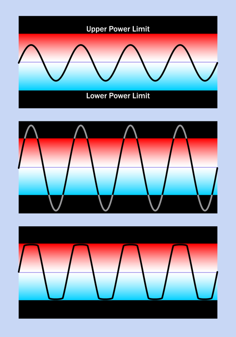
Figure 5-59. When a sine wave (top) is passed through an amplifier that is turned up beyond the limit of its components, the amplifier chops the wave (bottom).
For rock guitarists, clipping sounded good, and “stomp boxes” were introduced to create the effect. A very early example is shown in Figure 5-60
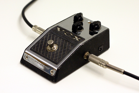
Figure 5-60. This Vox Wow-Fuzz pedal was one of the early stomp boxes, which deliberately induced the kind of distortion that audio engineers had been trying to get rid of for decades.
Background: Stomp-Box Origins
The Ventures recorded the first single to use a fuzz box, titled “The 2,000 Pound Bee,” in 1962. Truly one of the most awful instrumentals ever made, it used distortion as a gimmick and must have made other musicians conclude that this was a sound destined for oblivion.
Then Ray Davies of the Kinks started experimenting with distortion, initially by plugging the output from one amp into the input of another, supposedly during the recording of his hit “You Really Got Me.” This overloaded the input and created clipping that sounded more musically acceptable. From there it was a short step to Keith Richards using a Gibson Maestro Fuzz-Tone when the Rolling Stones recorded “(I Can’t Get No) Satisfaction” in 1965.
Today, you can find thousands of advocates promoting as many different mythologies about “ideal” distortion. In Figure 5-61, I’ve included a schematic from Flavio Dellepiane, a circuit designer in Italy who gives away his work (with a little help from Google AdSense).
Flavio is a self-taught Maker, having gained much of his knowledge from electronics magazines such as the old British publication, Wireless World. In the fuzz circuit that I’m including here, he uses a very high-gain amplifier consisting of three field-effect transistors (FETs), which closely imitate the rounded square wave typical of an overdriven tube amp.
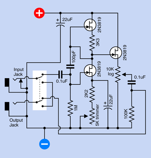
Figure 5-61. This circuit designed by Flavio Dellepiane uses three transistors to simulate the kind of distortion that used to be created by overloading the input of a tube amplifier.
Flavio offers dozens more schematics on his site, developed and tested with a dual-trace oscilloscope, low-distortion sinewave oscillator (so that he can give audio devices a “clean” input before he abuses it), distortion meter, and precision audio voltmeter. This last item, and the oscillator, were built from his own designs, and he gives away their schematics, too. Thus his site provides one-stop shopping for home-audio electronics hobbyists in search of a self-administered education.
Before fuzz, there was tremolo. A lot of people confuse this with vibrato, so let’s clarify that distinction right now:
-
Vibrato applied to a note makes the frequency waver up and down, as if a guitarist is bending the strings.
-
Tremolo applied to a note makes its volume fluctuate, as if someone is turning the volume control of an electric guitar up and down very quickly.
Harry DeArmond sold the first tremolo box, which he named the Trem-Trol. It looked like an antique portable radio, with two dials on the front and a carrying handle on top. Perhaps in an effort to cut costs, DeArmond didn’t use any electronic components. His steam-punkish Trem-Trol contained a motor fitted with a tapered shaft, with a rubber wheel pressing against it. The speed of the wheel varied when you turned a knob to reposition the wheel up and down the shaft. The wheel, in turn, cranked a little capsule of “hydro-fluid,” in which two wires were immersed, carrying the audio signal. As the capsule rocked to and fro, the fluid sloshed from side to side, and the resistance between the electrodes fluctuated. This modulated the audio output.
Today, Trem-Trols are an antique collectible. Johann Burkard has posted an MP3 of his DeArmond Trem-Trol online so you can actually hear it.
The idea of using a mechanical source for electronic sound mods didn’t end there. The original Hammond organs derived their unique, rich sound from a set of toothed wheels turned by a motor. Each wheel created a fluctuating inductance in a sensor like the record head from a cassette player.
It’s fun to think of other possibilities for motor-driven stomp boxes. Going back to tremolo: imagine a transparent disc masked with black paint, except for a circular stripe that tapers at each end. While the disc rotates, if you shine a bright LED through the transparent stripe toward a phototransistor, you have the basis for a tremolo device. You could even create never-before-heard tremolo effects by keeping a library of discs with different stripe patterns. Figure 5-62 shows what I have in mind, while Figure 5-63 suggests some disc patterns. For a real fabrication challenge, how about an automatic disc changer?
In the world of solid-state electronics, today’s guitarists can choose from a smorgasbord of effects, all of which can be home-built using plans available online. For reference, try these special-interest books:
Analog Man’s Guide to Vintage Effects by Tom Hughes (For Musicians Only Publishing, 2004). This is a guide to every vintage stomp box and pedal you can imagine.
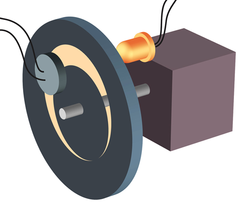
Figure 5-62. A hypothetical neo-electromechanical tremolo generator.

Figure 5-63. Different stripe patterns could be used to create various tremolo effects.
How to Modify Effect Pedals for Guitar and Bass by Brian Wampler (Custom Books Publishing, 2007). This is an extremely detailed guide for beginners with little or no prior knowledge. Currently it is available only by download, from sites such as Open Library.
but you may be able to find the previously printed edition from secondhand sellers, if you search for the title and the author.
Of course, you can always take a shortcut by laying down a couple hundred dollars for off-the-shelf stomp boxes that use digital processing to emulate distortion, metal, fuzz, chorus, phaser, flanger, tremolo, delay, reverb, and several more, all in one convenient package. Purists, of course, will claim that it “doesn’t quite sound the same,” but maybe that’s not the point. Some of us simply can’t get no satisfaction until we build our own stomp box and then tweak it, in search of a sound that doesn’t come off-the-shelf and is wholly our own.
Experiment 31: One Radio, No Solder, No Power
Getting back to the principle of inductance, I want to show you how it can enable a simple circuit that receives AM radio signals without a power supply. This is often known as a crystal radio, because the earliest examples used a natural mineral crystal that functioned as a semiconductor. The idea originated at the dawn of telecommunications, but if you’ve never tried it, you’ve missed an experience that is truly magical.
What You Will Need
-
Rigid cylindrical object, about three inches in diameter, such as a vitamin bottle or water bottle (1)
-
Hookup wire, 22 gauge, 60 feet minimum
-
Heavier wire, 16 gauge preferred, 50 to 100 feet (this wire may be stranded, and you can try a thinner gauge to reduce the cost, although your radio may not pull in so many stations)
-
Polypropylene rope (“poly rope”) or nylon rope, 10 feet
-
Germanium diode (1)
-
High-impedance earphone (1)
-
Test lead (1)
-
Alligator clips (3) or use extra test leads
Optional:
-
9-volt power supply (battery or AC adapter)
-
LM386 single-chip amplifier
-
Small loudspeaker (2” acceptable)
The diode and headphone can be ordered from the Scitoys Catalog. A high-impedance earphone is also available from amazon.com.
Step 1: The Coil
You need to create a coil that will resonate with radio transmissions in the AM waveband. The coil will consist of 65 turns of 22-gauge hookup wire, measuring approximately 60 feet.
You can wind the coil around any empty glass or plastic container, so long as it has parallel sides providing a constant diameter close to 3”. A water bottle will do, if it isn’t the type made of extremely thin plastic that will be easily squashed or deformed under pressure.
I just happened to have a vitamin bottle that was exactly the right size. In the photographs, you’ll notice that it has no label. I softened its adhesive with a heat gun (lightly, to avoid melting the bottle) and then peeled it off. Some remaining adhesive residue was removed with a little xylene.
After you prepare a clean, rigid bottle, use a sharp object such as an awl or a nail to punch two pairs of holes in it, as shown in Figure 5-64. The holes will be used to anchor the ends of the coil.
Strip some insulation from the end of your hookup wire, and anchor it in one pair of holes, as shown in Figure 5-65. Now wrap five turns of wire around the bottle, and keep it from unwinding itself by applying a small, temporary piece of tape. Duct tape is ideal, or regular Scotch tape will do. “Magic” tape isn’t strong enough and will be difficult to remove.

Figure 5-64. The holes will anchor wire wrapped around the bottle.
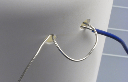
Figure 5-65. Anchor one end of your wire in a pair of holes.
Now you need to strip away about half an inch of insulation from the wire. The idea is that you should be able to tap into the coil at this point. Using your wire strippers, make an incision in the insulation and then pull the plastic coating away from your incision. See Figure 5-66.
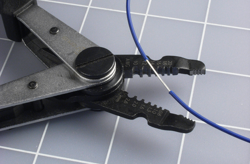
Figure 5-66. Use your wire strippers and your thumbnails to pull back about half an inch of insulation.
The next step is to twist the exposed wire into a loop, to make it easily accessible and prevent the insulation from closing up. See Figure 5-67.

Figure 5-67. Create a loop in the section of wire that you exposed.
You just created a tap on your coil. Remove the piece of tape that you used to hold your first five turns temporarily, and wind another five turns around the bottle. Apply the tape again, and create another tap. You’ll need a total of 12 of them, altogether. It doesn’t matter if they don’t line up with each other precisely. When you have made the last tap, wind five more turns around the bottle and then cut the wire. Bend the end into a U shape about a half-inch in diameter, so that you can hook it through the pair of holes that you drilled at the far end of the bottle. Pull the wire through, then loop it around again to make a secure anchor point.
My coil wrapped around a vitamin bottle is shown in Figure 5-68.
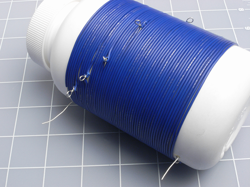
Figure 5-68. The completed coil, wrapped tightly around the bottle.
Your next step is to set up an antenna, which will be a section of wire that is as thick as possible and as long as possible. If you live in a house with a yard outside, this is easy: just open a window, toss out a reel of 16-gauge wire while holding the free end, then go outside and string up your antenna by using polypropylene rope (“poly rope”) or nylon rope, available from any hardware store, to hang the wire from any available trees, gutters, or poles. The total length of the wire should be 50 to 100 feet. Where it comes in through the window, suspend it on another length of poly rope. The idea is to keep your antenna wire as far away from the ground or from any grounded objects as possible.
If you don’t have an accessible yard, you can string up your antenna indoors, hanging it with poly rope or nylon rope from window treatments, door knobs, or anything else that will keep it off the floor. The antenna doesn’t have to be in a straight line; in fact you can run it all around the room.
Caution: High Voltage!
The world around us is full of electricity. Normally we’re unaware of it, but a thunderstorm is a sudden reminder that there’s a huge electrical potential between the ground below and the clouds above.
If you put up an outdoor antenna, never use it if there is any chance of a lightning strike. This can be extremely dangerous. Disconnect the indoor end of your antenna, drag it outside, and push the end of the wire into the ground to make it safe.
Antenna and Ground
Use an alligator test lead to connect the end of your antenna wire with the top end of the coil that you made.
Next you need to establish a ground wire. This literally has to connect with the ground outside. Ideally, you should bury a couple of feet of bare wire in soft, moist earth—although this may be problematic if you live in a desert area, as I do. If you use a grounding stake of the type sold by wholesale electrical supply houses to ground welding equipment, be careful where you hammer it into the ground. You don’t want to hit any hidden conduits.
A cold-water pipe is often suggested as a good connection with the ground, but (duh!) this will work only if the pipe is made of metal. Even if your home is plumbed with copper pipes, a section may have been repaired and replaced with plastic at some time in the past.
Probably the most reliable option is to attach the wire to the screw in the cover plate of an electrical outlet, as the electrical system in your house will be ultimately grounded. But be sure to anchor the wire securely, so there is absolutely no risk of it touching the sockets in the outlet. I would prefer not to insert the ground wire in the ground socket of the outlet, because there is the risk of poking it into the live socket by mistake.
Now you need a couple of slightly hard-to-find items: a germanium diode, which functions like a silicon-based diode but is better suited to the tiny voltages and currents that you’ll be dealing with, and a high-impedance earphone. The kind of earphones or ear buds that you use with a media player will not work here; this has to be an old-school item, like the one shown in Figure 5-69. If it has a plug on the end, you’ll have to snip it off and then carefully strip insulation from the tip of each wire.
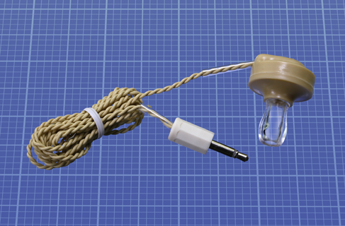
Figure 5-69. This is the type of earphone you need for your no-power radio.
The parts are assembled with test leads and alligator clips, as shown in Figure 5-70. The real-world version that I built isn’t as neat as the diagram, but the connections are still the same, as shown in Figure 5-71. Notice that the test lead at the bottom can latch on to any of the taps on your coil. This is how you will be tuning your radio.

Figure 5-70. The assembled components.

Figure 5-71. The real-world version.
If you followed the instructions, and you live within 20 or 30 miles of an AM radio station, and your hearing is reasonably good, you will be able to listen to the faint sounds of radio on your earphone—even though you are not applying any power to the circuit that you built. This project is many decades old, but can still be a source of surprise and wonder. (See Figure 5-72.)
If you live too far from a radio station, or you can’t put up a very long antenna, or your ground connection isn’t very good, you may not hear anything. Don’t give up; wait till sunset. AM radio reception changes radically when the sun is no longer exciting the atmosphere with its radiation.
To choose among radio stations, move the alligator clip at the end of your test lead from one tap to another on your coil. Depending on where you live, you may pick up just one station, or several, playing individually or simultaneously.

Figure 5-72. The simple pleasure of picking up a radio signal with ultra-simple components and no additional power.
It may seem that you’re getting something for nothing here, but really you are taking energy from a source of power—the transmitter located at a radio station. A transmitter pumps power into a broadcasting tower, modulating a fixed frequency. When the combination of your coil and antenna resonates with that frequency, you’re sucking in just enough voltage and current to energize a high-impedance headphone.
The reason you had to make a good ground connection is that power will only flow through your coil if it has somewhere to go. You can think of the ground as being an almost infinite power sink, with a reference voltage of zero. The transmitter at an AM radio station is also likely to have a potential relative to ground. See Figure 5-73.
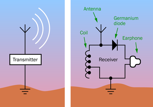
Figure 5-73. Your no-power radio takes just enough energy from a distant transmitter to create a barely audible sound in your earphone.
Enhancements
If you have difficulty hearing anything through your earphone, try substituting a piezoelectric transducer, also known as a piezo beeper. You need the type that does not have an oscillator built in, and functions passively, like a loudspeaker. Press it tightly against your ear, and you may find that it works as well as an earphone, or better.
You can also try amplifying the signal. Ideally you should use an op-amp for the first stage, because it has a very high impedance. However, I decided to put op-amps in Make: More Electronics, where I had room to explore the topic more thoroughly. As a substitute, you can feed the signal directly into the same LM386 single-chip amplifier from Experiment 29.
Figure 5-74 shows how simple the circuit can be. The germanium diode can connect directly with the LM386 input, as I don’t think you’ll need a volume control. Be sure to include the 10µF capacitor between pins 1 and 8, to increase the amplification of the chip to its maximum value. Even where I live, about 120 miles from Phoenix, Arizona, I was able to pick up a station broadcasting from the Phoenix area.

Figure 5-74. The LM386 single-chip amplifier can make your crystal-set radio audible through a loudspeaker.
If you want to improve the selectivity of your radio, you can add a variable capacitor to tune the resonance of your circuit more precisely. Variable capacitors are uncommon today, but you can find one at the same specialty source that I recommended for the earphone and the germanium diode: the Scitoys Catalog.
This source is run by a smart man named Simon Quellan Field, whose site suggests many fun projects that you can pursue at home. One of his clever ideas is to remove the germanium diode from your radio circuit and substitute a low-current LED in series with a 1.5-volt battery. This didn’t work for me, because I live in a remote location; but if you’re close to a transmitter, you may be able to see the LED varying in intensity as the broadcast power runs through it.
Theory: How Radio Works
High-frequency electromagnetic radiation can travel for miles. To make a radio transmitter, I could use a 555 timer chip running at, say, 850 kHz (850,000 cycles per second), and would pass this stream of pulses through an extremely powerful amplifier to a transmission tower—or maybe just a long piece of wire. If you had some way to block out all the other electromagnetic activity in the air, you could detect my signal and amplify it.
This was more or less what Guglielmo Marconi did when he performed a groundbreaking experiment in 1901, except that he had to use a primitive spark gap, rather than a 555 timer, to create the oscillations. His transmissions were of limited use, because they had only two states: on or off. You could send Morse code messages, and that was all.
Marconi is pictured in Figure 5-75.

Figure 5-75. Guglielmo Marconi, the great pioneer of radio (photograph from Wikimedia Commons).
Five years later, the first true audio signal was transmitted by imposing lower audio frequencies on the high-frequency carrier wave. In other words, the audio signal was “added” to the carrier frequency, so that the power of the carrier varied with the peaks and valleys of the audio. This is shown in Figure 5-76.
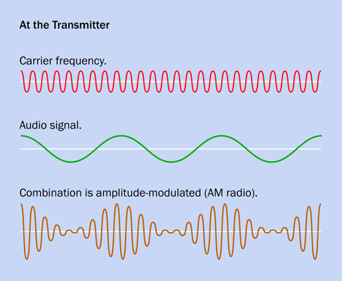
Figure 5-76. Using a carrier wave of fixed frequency to transmit an audio signal.
At the receiving end, a very simple combination of a capacitor and a coil detected the carrier frequency out of all the other noise in the electromagnetic spectrum. The values of the capacitor and the coil were chosen so that their circuit would resonate at the same frequency as the carrier wave. The basic circuit is shown in Figure 5-77, where the variable capacitor is represented by a capacitor symbol with an arrow through it.

Figure 5-77. When a variable capacitor is added to the previous circuit, it enables better discrimination among different signals sharing the spectrum.
The carrier wave fluctuates up and down so rapidly, an earphone cannot possibly keep up with the positive-negative variations. It will remain hesitating at the midpoint between the highs and lows, producing no sound at all. A diode solves this problem by blocking the lower half of the signal, leaving just the positive voltage spikes. Although these are still very small and rapid, they are now all pushing the diaphragm of the earphone in the same direction, so that it averages them out, approximately reconstructing the original sound wave. This is shown in Figure 5-78.
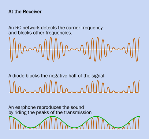
Figure 5-78. How a simple AM radio receiver decodes the signal and reproduces it on an earphone.
When a capacitor is added to a receiving circuit, an incoming pulse from the transmitter is initially blocked by the self-inductance of the coil, while it charges the capacitor. If an equally negative pulse is received after an interval that is properly synchronized with the values of the coil and the capacitor, it coincides with the capacitor discharging and the coil conducting. In this way, the right frequency of carrier wave makes the circuit resonate in sympathy. At the same time, audio-frequency fluctuations in the strength of the signal are translated into fluctuations in voltage in the circuit.
If you are wondering what happens to other frequencies pulled in by the antenna, the lower ones pass through the coil to ground, while the higher ones pass through the capacitor to ground. They are just “thrown away.”
The waveband allocated to AM radio ranges from 300kHz to 3MHz in carrier frequencies. Many other frequencies are allocated for special purposes, such as ham radio. It’s not so difficult to pass the ham radio exam, and with appropriate equipment and a well-situated antenna, you can talk directly with people in widely scattered locations—without relying on any communications network to connect you.
Experiment 32: Hardware Meets Software
I’m guessing that many readers of this book—perhaps most readers—have heard of the Arduino. This experiment, and the next two, will show you how you can set up an Arduino and then write programs for it, instead of just downloading applications that you find online.
What You Will Need
-
Arduino Uno board, or compatible clone (1)
-
USB cable with A-type and B-type connector at opposite ends (1)
-
A desktop or laptop computer with an available USB port (1)
-
Generic LED (1)
Definitions
A microcontroller is a chip that works like a little computer. You write a program consisting of instructions that the microcontroller can understand, and copy them into some memory in the chip. The memory is nonvolatile, meaning that it will preserve its contents even when the power is switched off.
Normally I would suggest jumping right in and writing a program, but learning to use a microcontroller entails a bigger investment of time and mental energy than was required by the components that I have dealt with previously. How do you know if you want to get into this, until you know some more details? Therefore, I must begin with an explanation and orientation. After that, this experiment will take you through the process of setting up an Arduino and performing the most basic test. Experiments 33 and 34 will take you further into programming the Arduino and using other components in conjunction with it.
The setup-and-test procedure may take an hour or two. You should allocate the time when you will be able to follow the instructions without distraction. Once you have gone through this initial process, everything will be much easier.
Real-World Applications
A typical microcontroller application might run like this:
-
Receive an input from a rotational encoder that is functioning as a volume control on a car stereo.
-
Figure out which way the encoder is rotating.
-
Count the pulses from the encoder.
-
Tell a programmable resistor how many equivalent steps it should take, to adjust the volume of the stereo up or down.
-
Wait for more inputs.
A microcontroller could also handle a much larger application, such as all the inputs, outputs, and decisions associated with the intrusion alarm system in Experiment 15. It would scan sensors, activate a siren through a relay after a delay period, receive and verify a keypad sequence when you want to shut off the alarm—and much more.
All modern cars contain microcontrollers, which deal with complex tasks such as timing the ignition in the engine—and simple matters such as sounding a chime if you don’t fasten your seat belt.
A microcontroller can handle small but important tasks that I discussed in previous experiments, such as debouncing a pushbutton or generating an audio frequency.
Bearing in mind that one little chip can do so many different things, why don’t we use it for everything?
The Right Tool for the Job?
A microcontroller is versatile and powerful, but is more suitable in some situations than others. It is ideal for applying logical operations along the lines, “If this happens, do that, but if that happens, do something else,” but it adds cost and complexity to a project, and of course it entails a major learning process: you have to master the computer language that tells the microcontroller what to do.
If you don’t want to learn the language, you can download and use programs that other people have written. Many Makers use this option, because it provides immediate results. You can find thousands of Arduino programs in libraries online, and they cost nothing.
But a program probably won’t do exactly what you want. Inevitably, you will need to modify it—and you will be back in a situation where you need to understand the language in order to get full use out of the chip.
Writing a program for the Arduino can be relatively simple, depending on the application. However, it is not a one-step operation. The code has to be tested, and the processes of revision and debugging can be time-consuming. One little error will create unexpected results, or can stop anything from happening at all. You have to re-read your code, find the mistakes, and try again.
After you have everything working, the results can be impressive. For this reason, personally I think that programming a microcontroller is worthwhile, so long as your expectations are realistic.
You will have to try it for yourself to find out if it’s something you want to pursue actively.
One Board, Many Chips
I’ll begin with the most basic question. What is an Arduino?
If you think that it’s a chip, you are not quite correct. Each product with the Arduino name on it consists of a small circuit board designed by Arduino, containing a microcontroller chip made by a completely different company. The Arduino Uno board uses an Atmel ATmega 328P-PU microcontroller. The board also includes a voltage regulator, some sockets that enable you to plug in wires or LEDs, a crystal oscillator, a power-supply connector, and a USB adapter that enables your computer to communicate with the board. See Figure 5-79 for a photograph of the board with some of the components identified.

Figure 5-79. An Arduino Uno board, featuring the ATmega 328P-PU microcontroller made by Atmel.
If you buy an ATmega 328P-PU on its own from a component supplier, it will cost you less than one-sixth the retail price of an Arduino board containing the chip. Why should you have to pay so much more, just to get that little circuit board? The answer is that development of the board and the clever software that enables you to use it was not a trivial matter.
The clever software is called an IDE, which is an acronym for integrated development environment. After you install it on your computer, the IDE is a user-friendly place in which to write a program and then compile it, meaning that it converts the C language instructions (which human beings can understand) into machine code (which the Atmel chip will understand). You then copy it to the ATmega chip.
In case this is confusing, I’ll summarize the story so far.
-
An Arduino is a circuit board into which is plugged an Atmel microcontroller.
-
IDE software written by the Arduino company enables you to write a program on your computer.
-
After you write your program, the IDE software compiles it, to create code that the chip understands.
-
The IDE software sends the code to the Atmel chip, which stores it.
Once your code is in the chip, the chip doesn’t really need the Arduino board anymore. Theoretically, you could unplug the ATmega328 and use it somewhere else—in a breadboard, or in a circuit that you solder around it. The chip will still do what you programmed it to do, because the code remains stored in the chip.
In reality there are some little snags associated with this, but you can learn about them by reading a very good book titled Make: AVR Programming by Elliot Williams. It tells you exactly how to transplant the ATmega chip.
If you learn how to do this, the implications are significant. You will only need one Arduino board, while you can buy a lot of Atmel chips very cheaply. Put one chip into the board, program it, remove it, and use it in a standalone project. Put another chip into the board, transfer a different program into it, and use it in a different project.
This is relatively easy if you have the version of the Arduino Uno where the microcontroller is a through-hole chip mounted in a socket. You can pry it out with a miniature screwdriver, and substitute another chip by pushing it in with your finger and thumb. (Another version of the Uno comes with a surface-mounted microcontroller, soldered in. This version does not allow you to relocate the chip.)
Beware of Imitations?
Now that I have explained the basics, I’ll explain how to set everything up.
While various models of Arduino exist, the one I’m going to deal with here is the Arduino Uno, and my instructions will apply to version R3 or later.
You can buy the Arduino board from many sources, because it was designed and marketed as an “open source” product, allowing anyone to create a copy of it, just as any manufacturer can make a 555 timer (although for slightly different reasons).
Mouser, Digikey, Maker Shed, Sparkfun, and Adafruit all sell genuine Arduino products. On eBay, however, you can find unlicensed copies of the Arduino board for one-third of the price. You can see that they are unlicensed, because they don’t have the Arduino logo printed on them. To help you in distinguishing the real boards from the imitations, you can see the logo at Figure 5-80.

Figure 5-80. Only the boards manufactured or licensed by Arduino are supposed to have this logo on them.
The unlicensed boards are completely legal. This is not like buying pirated software or music. The only feature that Arduino chose to control is its trademark, which may not be used by other manufacturers. (Actually, some scammers use the logo illegally, but you’ll know they are not genuine Arduino boards, because they’re so cheap.) Just to make things more complicated, because of a dispute between Arduino and its former manufacturer, authentic Arduino boards are marketed under the name Genuino outside of the United States.
If you buy an imitation board, will it be reliable? I would trust the ones from Adafruit, Sparkfun, Solarbotics, Evil Mad Scientist, and a few others. I can’t buy and test them all, so you have to make up your own mind about this, based on feedback from other buyers and your general impression of a supplier. But remember, you only have to buy one board, after which you can use it to program multiple Atmel chips, using the plan I described above. So maybe it’s not such a big deal to pay a little extra for the genuine Arduino product. By doing so, you help the company to continue its development of new products in the future.
Personally, I bought a genuine Arduino board.
Setup
I will assume, now, that you have acquired an Arduino Uno, or an imitation that you believe is trustworthy. You will also need a standard USB cable with a type A plug on one end and a type B plug on the other end, as shown in Figure 5-81. This is not usually supplied when you buy the board on its own. If you don’t have a spare cable, you can borrow one from another device while you do your setup and initial test. Cables are cheaply available online from sites such as eBay.
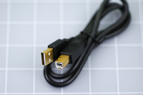
Figure 5-81. You will need this type of USB cable to attach your Arduino board to a USB port on your computer.
You have the board and the cable, so now you need the IDE software. Go to the Arduino website and click the “download” tab. Then choose the IDE software that is appropriate for your computer. It is currently available in variants for Mac OS, or Linux, or Windows. I will be using version 1.6.3, but my instructions should also apply to later versions. You can download the IDE software for free.
Note that you need a computer running Windows XP or later, or running Mac OS X 10.7 or later, or Linux 32-bit, or Linux 64-bit. (These requirements are valid at the time of writing. Arduino may change its requirements in the future.)
The procedure for setup under the three different operating systems is described below, primarily based on instructions in the nice little introductory guide titled Getting Started with Arduino by Massimo Banzi and Michael Shiloh. You can also find installation instructions on sites such as SparkFun and Adafruit. Lastly, there are instructions on the Arduino website as well.
Unfortunately, all these instructions are slightly different. For instance, Arduino’s website tells me to plug in my board before running the installer, but the Getting Started book tells me to run the installer before plugging in my board. This makes my task difficult, because both the Arduino website and the Getting Started book were written in collaboration with Arduino developers.
Below I will give you my best guess about what will work on each system.
Linux Installation
This is likely to be the most challenging, as there are so many variants of the operating system. I will have to refer you to the Arduino site for guidance.
I regret that I can’t help you, myself, with Linux.
Windows Installation
I am inclined to use the procedure recommended in Getting Started with Arduino. This is also recommended at the website maintained by Sparkfun.
Do not plug in the board yet. First, identify the IDE installation program that you downloaded. Its name may be something like arduino-1.6.3-windows.exe, although by the time you read this, the version numbers almost certainly will have changed. The .exe at the end of the file name may not be visible, depending on the system settings on your computer.
-
Some guides refer to the installation download as being a zipped file, which has to be unzipped. So far as I can determine, file zipping has been discontinued by Arduino. You can run it as is.
Double-click the icon, and you should see an installation sequence that is familiar to you from installing other software from other vendors.
You have to agree to the terms of a licensing agreement (if you don’t agree, you can’t run the software).
You are asked if you want shortcuts on your desktop and in your Start menu. Allow the shortcut to be added to your desktop. The Start menu is up to you.
You will be asked to approve the installation folder for the IDE software, and you should accept the default that is suggested.
If you are a dinosaur like me, still using Windows XP (and actually, there are quite a few million of us), you may see a warning such as the one shown in Figure 5-82. The exact look of this will depend on your version of Windows. Ignore the warning by choosing to “continue anyway.” If you are asked permission to install device drivers, say “yes.”

Figure 5-82. Users of the old WinXP operating system can ignore this warning.
-
On Windows 8, a security feature prevents you from installing unsigned device drivers. This should not be an issue with modern versions of the Arduino IDE installer, but if you somehow obtain older versions from somewhere else, you can Google:
sparkfun disable driver signingwhich should take you to the section of the Sparkfun site that contains helpful advice on the topic.
After installing the IDE software, plug your Arduino into your computer with the USB cable.
You don’t need to use the circular power input jack on the Arduino board, so long as the board is connected with a USB port on your computer. The board receives power through the USB cable. Bear in mind that a shorter, thicker cable will minimize voltage drop. Also, if you are using a laptop computer, especially if it is an older one, it may limit the power that you can draw from a USB port to 250mA. Even on a desktop computer, which is supposed to deliver 500mA via USB, that power may be shared across three or four USB ports. A device such as an external hard drive can take a significant amount.
Watch the board while it identifies itself to the computer. You should see a green LED that lights up steadily, and a yellow LED that blinks. A couple more LEDs nearby on the board, labeled TX and RX, should flicker briefly. They show that data is being transmitted and received.
On your computer, go to the shortcut for the IDE software. It is simply named “Arduino,” and the installer placed it on your desktop. If you don’t want it on the desktop, drag it to a different location. Double-click it to launch the Arduino IDE software.
In the window that opens, pull down the Tools menu, go to the Ports submenu (which is currently named Serial Ports in the Mac version), and you should see a list of serial ports on your computer. They will be named COM1, COM2, and upward.
What is a serial port? In the early days of Windows (and before that, MS-DOS) computers didn’t have USB connectors. They used “serial protocol” through D-shaped connectors, and the computer kept track of the connector that it was using by assigning it a “port number.” This system is still buried in Windows, even though decades have passed since it was established and the protocol has become rare for domestic applications.
All you need to know is if the Arduino IDE software and Windows have agreed on the port number that has been assigned to your Uno board. Ideally, when you choose Tools > Ports in the IDE software, you will see the Uno in the list with a check mark beside it, and everything is fine. If so, skip the troubleshooting section that follows, and go directly to the Old Arduino Blink Test, below (see “The Old Arduino Blink Test”).
Windows Troubleshooting
There are two bad possibilities that can affect your port assignment.
-
In the Port submenu of the Arduino IDE software, you may see the Arduino Uno listed, but it is not checkmarked. Another port may be checkmarked instead. Try checkmarking the correct port. You may see a warning if the IDE software doesn’t approve of the Uno board that you are using. Ignore the warning, click the box saying “Don’t show me this again,” and proceed to the Old Arduino Blink Test (see “The Old Arduino Blink Test”).
-
You may see no port in the list labeled Arduino Uno. In that case, make a note of the COM ports that are listed. Close the IDE menus. Unplug the Uno board. Wait five seconds. Open the IDE Port submenu again, and see which COM port has disappeared. Close the submenu. Plug the Uno back in. Reopen the submenu. Click the port that has reappeared, to checkmark it. Proceed to the Old Arduino Blink Test (see “The Old Arduino Blink Test”).
Windows allows you an option to verify your port settings. Click your Start menu and choose the Help and Support service. In the window that opens, type the words “Device Manager” as your search term. It should be the first hit in the list of search results. Open Device Manager. If you are using Windows XP, Device Manager shows you a Ports list. On versions of Windows later than XP, when you go to Device Manager you may have to select View > Show Hidden Devices to reveal the Ports list.
You should see your Arduino Uno listed there. If there is a yellow circle beside it, or an exclamation point, right-click it to find out what’s wrong.
If Windows complains that it cannot find the device driver for your board, tell it to look in the Arduino folder containing all the files that were extracted by the installer.
One known issue with the Arduino Uno and Windows ports is that the IDE software can get confused if you have more than nine ports already assigned. This is unusual, but if you have this problem, try unassigning some ports, or manually assign an unused port that has a single-digit number.
If you are still having difficulties, go to “If All Else Fails” below.
Mac Installation
After completing the IDE installer download, locate the icon that the computer has created, double-click it, and you’ll see a disk image that contains the Arduino IDE software. You can drag this into your Applications folder.
Now plug your Arduino into your computer with the USB cable.
-
You don’t need to use the circular power input jack on the Arduino board, so long as the board is connected with your computer. The board takes its power through the USB cable.
Watch the board while it identifies itself to the computer, and you should see a green LED that lights up steadily, and a yellow LED that blinks. A couple more LEDs nearby on the board, labelled TX and RX, should flicker briefly. They show that data is being transmitted and received.
If a window opens telling you that a “new network interface” has been detected, click Network Preferences, and then Apply. It doesn’t matter if the Uno is described as “not configured.” Close the window.
Double-click the program icon for the Arduino IDE that you dragged into your Applications folder. You need to select the correct port for communication with the Uno board. In the Tools menu of the IDE software, click the Serial Port option, and select /dev/cu.usbmodemfa141 (or a similarly named port) from the list that pops up.
If everything has proceeded as described here, you can continue with the Old Arduino Blink Test (see “The Old Arduino Blink Test”).
If All Else Fails
This book may stay in print for a while. At least, I hope it does! Software, on the other hand, changes frequently. My installation instructions for the Arduino IDE may be out of date by the time you read this.
I will try to revise my instructions in each new printing and each new ebook version, so that they will be as accurate as possible. But of course you may happen to be reading an older printing or an older ebook.
What to do? Your best bet is to go to the Arduino site, or the Sparkfun site, and follow installation procedures listed there. A website is more easily and quickly updated than a book.
The Old Arduino Blink Test
I am assuming that you have launched the IDE software. Its main window should look something like the screenshot in Figure 5-83, although subsequent versions may change somewhat.
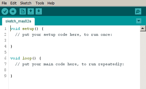
Figure 5-83. Default window that opens when the Arduino IDE is launched.
Before you can make your Arduino do something, you have to check that the IDE software has correctly identified the version of the board that you connected with your computer.
In the IDE main window, pull down the Tools menu, open the Boards submenu, and verify that the Arduino Uno has a bullet point beside it, as in Figure 5-84. If it doesn’t, click it to select it.
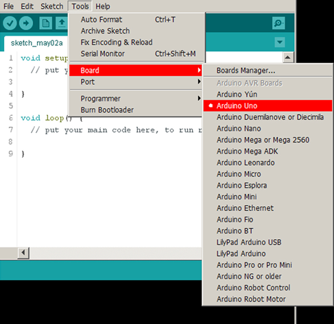
Figure 5-84. When you are using the Arduino Uno, it should have a bullet point beside it in the Boards Manager submenu.
Now you are ready to give your Arduino some instructions. At the top of the workspace in the main IDE window, you’ll see the word “sketch” followed by today’s date and the letter “a.” What is this “sketch”? Is it a picture that you are going to draw?
No, in the Arduino world, “sketch” means the same thing as “program.” Perhaps this is because the developers didn’t want to make people feel intimidated by the idea that they were going to program a computer. Similarly, while he was still alive, Steve Jobs seemed to feel that users of handheld devices would be more comfortable if he referred to programs as “apps.” Jobs was probably right, but where Makers are concerned, I don’t think they are so easily intimidated. In fact I think they want to program computers. Otherwise, why would you be reading this?
“Sketch” means “program” for the Arduino, but I will continue to use the word “program,” because that is what it really is, and I feel silly calling it a “sketch.” When you read source materials online, people use the word “program” at least as often as they use the word “sketch.”
Now I need to remind you of the sequence of events that we are going to follow. First, you write a program in the IDE window. Then you compile it by selecting a menu option, to convert it into instructions that a microcontroller can understand. Then you upload it to the Arduino board, and then the board automatically runs the program.
The IDE window on my computer contains some default text shown in Figure 5-83. Future versions of the IDE may do things a little differently, but the principle will be the same. You will see some lines beginning with two slash marks, like this:
// put your setup code here, to run once.
This is known as a comment line. It is for human interest, to explain what’s going on.
-
When the program that you write is compiled for the microcontroller, the compiler will ignore all lines that begin with // marks.
The next line reads:
void setup() {
This is a line of program code, for the compiler and the microcontroller to understand. But you need to know what it means, because the setup routine has to be at the beginning of every Arduino program, and I’m hoping you will start to write your own programs in the future.
The word void tells the compiler that this procedure won’t generate any numerical result or output.
The term setup() says that the following procedure is something that has to be done once only, right at the beginning.
Notice that there is a { mark following setup().
-
Every complete function in C language should be contained within a
{mark and a}mark.
Because a { mark must always be followed by a } mark, there must be a } mark somewhere on the opening screen. Yes, it’s a couple of lines farther down. There’s nothing between the { mark and the } mark, so there are no instructions in this procedure. This is because you are going to write them.
-
It doesn’t matter if
{and}are on separate lines. The compiler for the Arduino ignores line breaks and all whitespace larger than a single space between words. -
The
{and}are properly known as braces.
It’s time to type something on the empty line beneath “put your setup code here.” Try this:
pinMode(13, OUTPUT);
You have to type it exactly. The compiler won’t tolerate typographical errors. Also, because the C language is case sensitive, you must distinguish between uppercase and lowercase letters. pinMode must be pinMode, not pinmode or Pinmode. OUTPUT must be OUTPUT, not output or Output.
The word pinMode is a command to the Uno, telling it how to use one of its pins. The pin can receive data as an input, or can send data as an output. 13 is the pin number, and if you check your board, you’ll find one of the little connectors is identified as 13, right beside the yellow LED. I have selected 13 as an arbitrary choice.
A semicolon marks the end of the instruction.
-
A semicolon must be included at the end of each instruction. Always. Don’t forget!
Now move on down to the empty line below the message that says:
// put your main code here, to run repeatedly.
You can tell from the double slash marks that this is another comment line for your information. The compiler will ignore it. Below it, carefully type these instructions:
  void loop() {
  digitalWrite(13, HIGH);
  delay(100);
  digitalWrite(13, LOW);
  delay(100);
  }
If you have any prior familiarity with an Arduino, you’ll be groaning, now, as you think to yourself, “Oh no, it’s the old blink test!” Yes indeed, and that’s why I subtitled this section, “The Old Arduino Blink Test.” This is the program that almost everyone uses as a preliminary test (although I have changed the delay values, for reasons that will become apparent). Please humor me by typing the program into the IDE. I will be getting to some more challenging projects soon enough.
Also, you may be just a little sketchy on what some of the statements actually mean.
void means the same as before.
loop() is an instruction telling the Arduino to do something over and over again. What does it have to do? It has to obey the procedure between the braces.
digitalWrite is a command to send something out of a pin. Which pin? I am specifying 13 because its mode was defined previously.
-
You can’t use a digital pin unless you have previously specified what its mode will be.
What should the pin do? Go to a HIGH state.
Don’t forget the semicolon at the end of the instruction.
delay tells the Arduino to wait for a while. How long? 100 means 100 milliseconds. There are 1,000 milliseconds in a second, so the Arduino is going to wait for one-tenth of a second. During that time, pin 13 will stay high.
I think you can figure out what the next two lines mean.
In a moment, you can activate the program. But first, go to your board and insert the leads of an LED between connector 13 and the connector labelled GND, right beside it.
-
Make sure the short lead of the LED is in the GND connector.
-
The LED does not need a series resistor, as this is built in to connector 13.
The little yellow LED on my board was already blinking, by default, as soon as I plugged in the board. The LED that I just inserted also starts blinking, because the yellow surface-mount LED built into the board is wired in parallel with pin 13.
In previous versions of the Uno, the onboard LED did not start blinking as soon as you plugged in the board. In future versions, Arduino may disable this “blinking by default.” Either way, it doesn’t matter, because your program is going to change the blink rate.
Verify and Compile
Next you must check if you made any typographical errors. Pull down the Sketch menu and choose Verify/Compile, as shown in Figure 5-85. The IDE examines your code, and if it sees any problems, it complains about them.
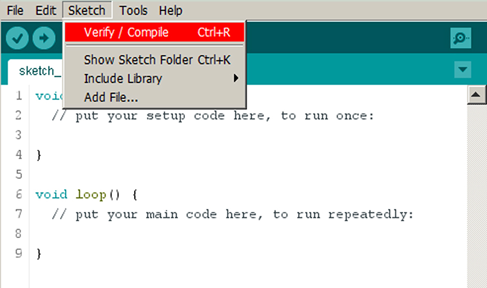
Figure 5-85. Choose the Verify/Compile option before sending your program to the Arduino.
You can test this. In your program listing, change pinMode to piMode, then Verify/Compile, and see what happens.
You get an error message in the black space at the bottom of the IDE window. You can stretch this black space by dragging its upper border with your mouse, so you can see more than two lines at a time, without scrolling them. The error message that I get says, "piMode was not declared in this scope.”
You see, there are reserved words and defined functions in the C language, which have special meanings. You have used a couple of them already, such as digitalWrite and delay.
But piMode doesn’t exist as a reserved word or defined function, so the compiler complains that you have not declared it, to say what it is.
Fix your program text till you can Compile/Verify without any errors.
Upload and Run
Now pull down the File menu, and choose Upload. Personally I always imagine that I am downloading from my big computer into the little Arduino, but everyone calls it uploading, so I guess that’s what it is.
If the upload is successful, you’ll see the message “Done Uploading” just above the black error window.
If it is not successful, and the uploading process never quite ends—this is not good. It means you still have some communications problems, probably because the COM port assignments don’t match. Go back to the troubleshooting section for your type of computer, above. But save your program first. Pull down the File menu, choose Save, and give your program a name. After you fix your COM issues, you will be able to reload the program, if necessary, and try again.
If everything worked as planned, the onboard yellow LED, and your LED, are now blinking rapidly—on for 1/10th of a second, and off for 1/10th of a second, in accordance with the instructions in your program.
You may feel that this is a small achievement after taking so many steps, but we have to start somewhere, and a blinking LED is usually where microcontroller programming begins. In the next experiment, you will write a new program that will do something much more useful.
Here’s a summary of what you may have learned so far, and what you generally have to do, to program the Arduino:
-
Start a new program (or “sketch,” as Arduino prefers to call it).
-
Select the New option from the File menu if necessary.
-
Every program must begin with a
setupfunction, which will run once only. -
You must declare the number of a digital pin, and its mode, by using the
pinModecommand, before you can do something with the pin later. -
The mode of a pin can be INPUT or OUTPUT.
-
Some pin numbers are not valid. Look at your Uno board to see the numbering system that is used.
-
A pair of braces must enclose every function or block in a program. But they can be on separate lines.
-
The compiler ignores line breaks and extra whitespace.
-
Every instruction in a function or block must end in a semicolon.
-
Every Arduino program must contain a
loopfunction (after thesetupfunction), which will run repeatedly. -
digitalWriteis a command to make a pin that is set for output have a state that is specified as HIGH or LOW. -
delaymakes the Arduino do nothing for a specified number of milliseconds (thousandths of a second). -
The numbers in parentheses after a command are parameters telling the Arduino how the command must be applied.
-
Use the Verify/Compile option in the Sketch menu to check your program before you try to upload it to the Arduino.
-
You must fix any errors found in the Verify/Compile operation.
-
Reserved words are a vocabulary of commands that the Arduino understands. You have to spell them correctly. Uppercase is considered different from lowercase.
-
After you upload your program, it will start running automatically, and will continue to do so until you disconnect power from the board or upload a new program.
-
There is a Reset button (a tactile switch) beside the USB connector on the Uno board. When you press it, the Arduino restarts your program at the beginning, with all the values reset.
Caution: Lost Code
If you modify your program and upload it to the microcontroller, the new version will overwrite the old version. In other words, the old version will be erased. If you didn’t save it on your computer under a different filename, it may be gone forever. Be very careful when uploading revised programs. Saving each version on your computer, under a new name, is a sensible precaution.
After program instructions have been uploaded into the microcontroller, there is no way to read them back out again.
Programming Entails Detail
I don’t know if you noticed, but the summary of points to remember, in this experiment, has been much longer than the summaries in any experiments where you used individual components. Writing a program entails a lot of detail, and you have to get everything exactly right. Personally I enjoy this, because once you get it right, it will always be right, and it will always work the same way. Programs never wear out. If you save them in a suitable medium, they can last forever. The software that I wrote in the 1980s will still run 30 years later in a DOS window on my desktop computer.
Some people don’t enjoy detail work, or they tend to make typing errors, or they don’t like the way in which a computer language makes inflexible demands (such as always insisting that you begin a program with a Setup function, even if you don’t have a setup). Different kinds of people enjoy different aspects of electronics, and that’s the way it should be. If everyone wanted to write programs, and no one ever wanted to touch a piece of hardware, we wouldn’t have any computers. It’s up to you to decide what activity suits you.
Personally, I’m going to continue with another experiment that uses the Arduino in a more interesting way. I want to show you how a microcontroller can do things more easily than individual components in some cases.
Before I end this experiment, though, you may be wondering what happens if you disconnect the Arduino from your computer.
-
The Arduino needs power to run your program.
-
The Arduino does not need power to store your program. The program is stored automatically in the microcontroller, like data in a flash drive.
-
If you want to run your program when the board is not connected with your computer, you have to provide power in the round black socket next to the USB socket on the board.
-
The power supply can range from 7VDC to 12VDC. It does not have to be regulated, because the Arduino board contains its own regulator, which changes your power input to 5VDC on the board. (Some Arduinos use 3.3VDC, but not the Uno.)
-
The power supply jack is 2.1mm in diameter, with center pin positive. You can buy a 9V AC-to-DC adapter with that kind of plug on its output wire.
-
If you connect external power while the Arduino is also connected with a USB cable, the Arduino automatically uses the external power.
-
You can disconnect your Arduino from the serial cable anytime, without bothering to use the “Safely Remove Hardware” option that exists in some versions of Windows.
Background: Origins and Options Among Programmable Chips
In factories and laboratories, many procedures are repetitive. A flow sensor may have to control a heating element. A motion sensor may have to adjust the speed of a motor. Microcontrollers are perfect for this kind of routine task.
A company named General Instrument introduced an early line of microcontrollers in 1976, and called them PICs, meaning Programmable Intelligent Computer—or Programmable Interface Controller, depending on which historical source you believe. General Instrument sold the PIC brand to another company named Microchip Technology, which owns it today.
Arduino uses Atmel microcontrollers, but PICs are still an alternative, and are used as the basis for a hobby-education version licensed by a British company named Revolution Education Ltd. They call their range of chips the PICAXE, for no apparent rational reason other than they must think that it sounds cool. (I’m not so sure that they’re right about that.)
The PICAXE comes with its own IDE, which uses a different computer language named BASIC. In some ways this is a simpler language than C. Another range of microcontrollers, the BASIC Stamp, also uses BASIC, with additional, more powerful commands.
If you search for PICAXE on Wikipedia, you’ll find an excellent introduction to all the various features. In fact, I think it’s a clearer overview than you’ll get from the PICAXE website.
Unlike the Arduino, you don’t need to buy a special board to program PICAXE chips. A customized USB cable is all you need—in addition to the appropriate IDE software, which you can download for free.
The first edition of this book contained some introductory information about PICAXE products. You can probably find that edition secondhand, if you’re interested.
Longevity
The flash memory that stores a program in an ATmega328 is guaranteed by the manufacturer for 10,000 read-write operations, with provision for automatically locking out memory locations that go bad. This would seem to be ample, and we may hope that a microcontroller will last almost indefinitely. However, we don’t know yet if it will really have the same longevity as an old-school logic chip, some of which are still working 40 years after they were manufactured. Does this matter? You have to make up your own mind about that.
Obsolescence
Microcontrollers are maturing rapidly as a technology. When I wrote the first edition of this book, the Arduino was relatively new, and its future was uncertain. The Arduino now dominates the hobby-electronics field, but what will the situation be another five years from now? No one knows. A product such as the Raspberry Pi is an entire computer on a chip. No one can predict whether it, or something else like it, will displace the Arduino.
Even if the Arduino remains the microcontroller system of choice, we have already seen new versions of the hardware, and updates to the IDE software that must be used when you program the chip. One way or another, you may have to keep yourself informed about developments in the field as they occur, and you may even have to abandon one brand of microcontroller and switch to a different brand.
By comparison, in most cases, individual components in through-hole format have reached the end of their development cycle. Some relatively recent innovations have been introduced, such as rotational encoders or small dot-matrix LED and LCD displays. However, most of these new products are designed for use with microcontrollers. In the simple world of transistors, diodes, capacitors, logic chips, and single-chip amplifiers, the knowledge that you acquire today should be valid 10 years from now.
Hybrid Circuits
Last, and perhaps most important, microcontrollers cannot be used alone. They always require some other component, even if it’s just a switch, a resistor, or an LED, and the other components must be properly compatible with the inputs and outputs of the microcontroller.
Therefore, to make practical use of a microcontroller, you still have to be familiar with electronics generally. You need to understand basic concepts such as voltage, current, resistance, capacitance, and inductance. You should probably know about transistors, diodes, alphanumeric displays, Boolean logic, and other topics that I have covered so far in this book. And if you are going to build prototypes, you will still need to know how to use a breadboard or make solder joints.
Bearing all this in mind, I can summarize the pros and cons.
Individual Components: Advantages
Simplicity.
Instant results.
No programming language needed.
Cheap, for small circuits.
Today’s knowledge will be valid tomorrow.
Better for analog applications such as audio.
Still necessary when using microcontrollers.
Individual Components: Disadvantages
Capable of performing one function only.
Circuit design is challenging for applications involving digital logic.
Not easily scalable. Large circuits are difficult to build.
Revisions to a circuit may be difficult or even impossible.
More components in a circuit generally require more power.
Microcontrollers: Advantages
Extremely versatile, able to perform many functions.
Additions or revisions to a circuit can be easy (just rewrite the program code).
Huge online libraries of applications, freely available.
Ideal for applications involving complex logic.
Microcontrollers: Disadvantages
Relatively expensive for small circuits.
Significant programming skills required.
Time-consuming development process: write code, install code, test, revise-and-debug, reinstall—in addition to troubleshooting the circuit hardware.
Rapidly evolving technology requires a continuing learning process.
Each microcontroller has individual quirks and features, requiring study and memorization.
Greater complexity means more things that can go wrong.
Requires a desktop or laptop computer, and data storage for programs. Data may be lost accidentally.
Requires a regulated power supply (usually 5VDC or 3.3VDC), like a logic chip. Limited output of 40mA per pin, or less. Cannot drive a relay or a loudspeaker, as a 555 timer can. You must buy a separate driver chip if you need to deliver more power.
Summing Up
Now I am ready to answer the question, “Should I use microcontrollers or individual components?”
My answer is that you need both. That is why I am including microcontrollers in a book that is primarily about individual components.
In the next experiment, I’ll show how a sensor and a microcontroller can work together.
Experiment 33: Checking the Real World
A switch is either “on” or “off,” but most of the inputs we receive from the real world tend to vary between those extremes. A thermistor, for instance, is a sensor that varies its electrical resistance over a wide range, depending on its temperature.
A microcontroller would be very useful if it could process that kind of input. For instance, it could receive the input from the thermistor, and then it could function like a thermostat, turning on a heater if the temperature falls below a minimum value, and turning off the heater when the room is warm enough.
The ATmega328 that is used in the Arduino Uno can do this, because six of its pins are classified as “analog inputs,” meaning that they don’t just evaluate an input as “logic-high” or “logic-low” on a digital basis. They convert it internally using what is called an analog-to-digital converter, or ADC.
On the 5-volt version of the Arduino, an analog input must range from 0VDC to 5VDC. (Actually, the upper limit can be modified, but that introduces some complexity that I will leave until later.) A thermistor doesn’t generate any voltage; it just varies its resistance. So, I’ll have to think of a way in which a change in resistance can deliver a change in voltage.
Once that problem has been dealt with, an ADC inside the microcontroller will convert the voltage on the analog pin into a digital value ranging from 0 through 1023. Why that numeric range? Because it can be expressed in 10 binary digits, and the ADC isn’t accurate enough to justify a wider range with smaller increments.
After the ADC has supplied a number, your program can compare it with a target value, and can take appropriate action—such as changing the state of an output pin, which can supply voltage to a solid-state relay, which can activate a room heater.
The sequence beginning with the thermistor and ending with the digital value is shown visually in Figure 5-86.

Figure 5-86. A simplified view of the plan for processing the status of a thermistor.
The following experiment will show you how to do this.
What You Will Need
-
Breadboard, hookup wire, wire cutters, wire strippers, test leads, multimeter
-
Thermistor, 10K, 1% or 5% accuracy (1) (This must be the NTC type, meaning that its resistance drops as the temperature increases. A PTC thermistor behaves oppositely)
-
Arduino Uno board (1)
-
Laptop or desktop computer with an available USB port (1)
-
USB cable with A-type and B-type connector at opposite ends (1)
-
6.8K resistor (1)
Using a Thermistor
The first step is to get to know your thermistor. It has very thin leads, because they must not conduct heat into or out of the tip where the temperature-measuring junction is located. The leads are probably too thin to plug into your breadboard reliably, so I suggest you grab them with a couple of alligator test leads, and use the leads to grab the probes of your meter, as shown in Figure 5-87.

Figure 5-87. Testing a thermistor.
The thermistor that I am recommending is rated at 10K. That’s its maximum resistance when it gets really cold. Its resistance doesn’t change much as the temperature rises until around 25 degrees Celsius (77 degrees Fahrenheit). After that, the resistance declines more rapidly.
You can test it with your meter. At room temperature, the thermistor should have a resistance around 9.5K. Now grip it between your finger and thumb. As it absorbs your body heat, its resistance goes down. At body temperature (arbitrarily agreed to be 37 degrees Celsius or 98.6 degrees Fahrenheit) its resistance is around 6.5K.
How can you convert this resistance range to the 0V to 5V required by the microcontroller?
First bear in mind that the maximum value corresponding with room temperature should actually be lower than 5V. The real world is an unpredictable place. What if your thermistor gets much hotter than you expected, for some surprising reason? Maybe you place your soldering iron beside it, or maybe you rest it on a warm piece of electronic equipment.
Here we have the first lesson in analog–digital conversion: allow for unexpected, extreme values when measuring the everyday world.
Range Conversion
The simplest way to convert the thermistor’s resistance into a voltage value is to choose a resistor approximately equal to the average resistance of the thermistor in the temperature range that interests us. Put the resistor and the thermistor in series to create a voltage divider, apply 5VDC at one end and 0VDC at the other end, then take the voltage at the midpoint between the components, as shown in Figure 5-88.

Figure 5-88. The simplest circuit for deriving a voltage from the changing resistance of a thermistor.
Normally, to set up this circuit, you would need to install a voltage regulator to provide the 5VDC. However, the Arduino has its own voltage regulator, and conveniently provides a 5VDC output (see Figure 5-79). You can tap into this output and take it across to your breadboard with a jumper wire. You’ll also need to tap one of the ground outputs from the Arduino, and take that to your breadboard as well.
When I tried that, and varied the thermistor temperature from around 25 to 37 Celsius, my meter measured a voltage from 2.1V to 2.5V. You should try that yourself, to check my numbers.
Obviously we run no risk of endangering the microcontroller with those voltages. But now I see a different problem: the range isn’t wide enough to achieve optimal accuracy.
Figure 5-89 shows the conversion between input voltage and internal digital equivalents. The range from 2.1V to 2.5V is defined by the darker blue rectangle. It will be converted into digital values from around 430 to 512, which is a spread of 82—only a small fraction of the complete range from 0 through 1,023.

Figure 5-89. Conversion graph from Arduino input voltage to ADC values. The blue rectangle identifies approximate voltages derived from a 10K thermistor in series with a 6.8K resistor, for temperatures between 75 and 95 degrees Fahrenheit.
Using this limited range will be like using a small number of pixels from a high-resolution photograph. Inevitably, there will be a lack of detail. Wouldn’t it be nice if we could somehow convert our voltages into a digital range covering maybe 500 values instead of 82 values?
One way to do that would be by amplifying the voltage, but that will entail using an additional component, such as an op-amp. This is possible, but then we will need resistors to control feedback, and everything will get complicated. The whole idea of the microcontroller was to keep it simple!
There is another option, which is to use a feature of the Arduino that sets a lower maximum voltage for the range. But this requires me to supply a sample of the new maximum voltage to one of the pins. To create that voltage, I would need to use another voltage divider, and then calculate a new conversion from voltage inputs to ADC values. Really, I want to avoid that kind of thing, at least until I have a simple program running.
After thinking about this a bit more—maybe I can live with a range of 82 values to represent a range from approximately 75 to 95 degrees Fahrenheit. That’s an accuracy of about 1/4 degree for each digital step created by the ADC. It’s not good enough for a clinical thermometer, but perfectly adequate for room temperature.
Connections
So let’s give it a try. But wait—are we still going to use a separate breadboard with that funky-looking Uno board on which the microcontroller is mounted?
Yes, that’s the plan. There are three ways to hook everything up:
-
You can buy a gadget called a protoshield, which is like a mini-breadboard that sits on top of the Uno board and plugs into the connectors. I am not a fan of this device, because it leads us away from an eventual finished circuit on a regular breadboard.
-
You can pry the microcontroller off the Uno board and plug it into a breadboard, where you can connect components with its pins in a normal manner. But if you do that, you have no way to load a program into the microcontroller, and you will need a crystal oscillator to make the microcontroller run at the same speed as when it was on the Arduino board.
-
You can mount your thermistor and resistor on a regular breadboard, and then run the voltage across from the thermistor circuit to the Uno board on a jumper wire, in the same way that you are already supplying positive voltage and ground from the Arduino to the breadboard. It’s messy, but it is what most people seem to do. If you finish a program and mount it permanently on the microcontroller, then maybe you can move the chip to a more convenient location.
Figure 5-90 shows the arrangement. Figure 5-91 shows how it looks in a photograph. I have to admit, this is one occasion where those little wires with plugs at each end are convenient, although I still don’t entirely trust them.

Figure 5-90. Wiring the thermistor circuit to the Arduino.
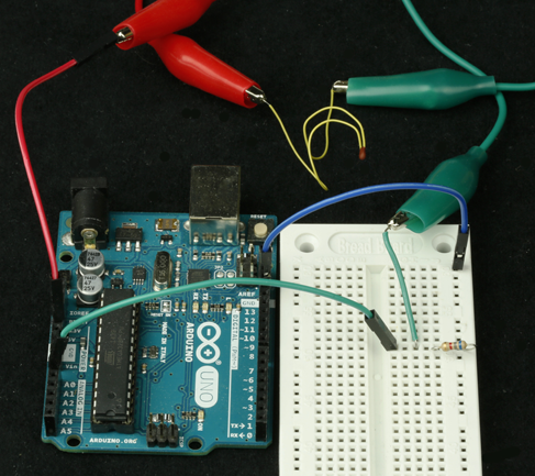
Figure 5-91. Using jumper wires to connect the thermistor circuit with the Arduino.
What, No Output?
Now you’re all set to convert an analog input to an internal digital value. But wait—something is missing, here. You don’t have an output!
In an ideal world, the Uno board would be sold with a nice little alphanumeric display, so that you could use it like a real computer. In fact, you can obtain displays like that which will work with the Uno, but once again this would entail some complexity. Like almost everything in the microcontroller world, it is not plug-and-play. The microcontroller has to be programmed to send text to the display.
So, I will keep things simple. I will use the little yellow LED on the Uno board as an indicator. I will pretend that the indicator represents a room heater, which comes on if the temperature is low and switches off when the temperature is high.
Hysteresis
Suppose we’re heating a greenhouse where we want the temperature to be a toasty 85 degrees Fahrenheit. Suppose the voltage from the resistor-thermistor combination is 2.3V at that temperature. Look it up on the graph in Figure 5-89 and you’ll see that the ADC inside the microcontroller will convert this to a digital value of around 470.
So, 470 is our threshold. If the number goes down to 469, we put on the heat (or simulate it, by lighting the LED). If the number goes up to 471, we turn off the heat.
But wait. Does this make sense? It means a fractional increase in temperature sensed by the thermistor will trigger the LED, and a fractional decrease will switch it off. The system will be forever fluctuating.
A real thermostat doesn’t respond to every little temperature variation when someone opens or closes a door. When it switches on, it stays on, until the temperature is a bit above the target. Then when the heat is off, it stays off, until the temperature is a bit below the target.
This behavior is known as hysteresis, and I discuss it in more detail, in relation to a component called a comparator, in my sequel to this book, Make: More Electronics.
How can we implement hysteresis in a microcontroller program? We need a broader range of values than 469 through 471. The program could say something like, “If the LED is on, keep it on until the temperature value exceeds 490. Then switch if off.” And, “If the LED is off, keep it off until the temperature value drops below 460. Then switch it on.”
Can we do this? Yes, quite easily. The program listed in Figure 5-92 uses this logic. I derived it from a screen capture of the Arduino IDE, so I have good reason to think that it works.
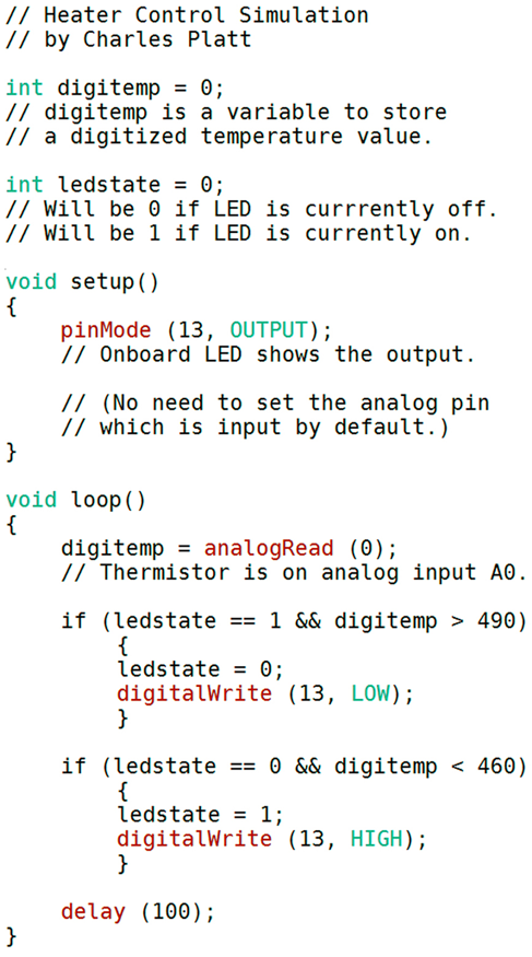
Figure 5-92. Program listing for control of an imaginary heating device.
The program also introduces some new concepts—but first, type it into the IDE. You don’t need to include all the comment lines, which I just added as explanations. You can type the much shorter version in Figure 5-93 where the comment lines have been omitted.
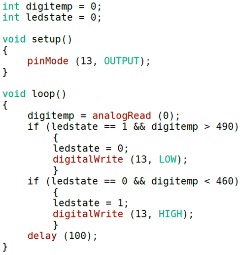
Figure 5-93. The same program as before, with the comment lines omitted.
Verify/Compile your program, and fix any typing errors (probably there will be a semicolon missing in one place or another—that’s the most common error).
Plug in your Arduino, upload the program, and if the temperature of your thermistor is below 85 degrees Fahrenheit, the yellow LED should switch on.
Hold the thermistor between your finger and thumb to make the thermistor think that the room temperature has increased. After a few seconds, the LED goes out. Now let go of the thermistor, and it cools down—but the LED stays on for a while, because the hysteresis in the system is telling it to wait until the temperature is sufficiently low. Eventually, the LED switches on again. Success!
But how does the program work?
Line by Line
This program introduces the concept of a variable. This is a little space in the microcontroller’s memory where a digital value can be stored. You can think of it as a “memory box.” On the outside of the box is a label that has the name of the variable. On the inside is a numeric value.
int digitemp = 0; means I have invented a variable named digitemp. It is an integer (a whole number), and it starts with a value of zero.
int ledstate = 0; means I have invented another integer variable, to keep track of whether the LED on the board is on or off. There’s no easy way I can get the microcontroller to look at the LED and tell me what its state is, so I will have to keep track of it myself.
The setup of the program just tells the microcontroller to use pin 13 as an output. I don’t need to tell it to use pin A0 as an input, because analog pins are inputs by default.
Now comes the heart of the program, in the loop. First, I use the command analogRead to tell the microcontroller to read the state of an analog port. Which one? I specify 0, which means analog port A0. This is where the connection from my breadboard is plugged in.
What do I do with the information from the ADC after it reads the port? There is only one sensible place to put it: in the variable named digitemp that I created for this purpose.
Now that digitemp contains a value, I can examine it. First I want to say, if the heat is on (the LED is illuminated) and the temperature value is greater than 490, it’s time to turn the heat off. The “if” part is tested like this:
if (ledstate == 1 && digitemp > 490)
The double == means, “make a comparison and see if these two items are the same.” A single equals sign means, “assign this value to a variable,” which is a different operation.
The double && is a “logical AND.” Yes, we have Boolean logic here, just as if we were using an AND logic gate. But instead of wiring up a chip, we just type a line of code.
The > symbol means, “is greater than.”
The “if” test is contained in parentheses. If the statement in the parentheses is true, the microcontroller performs the following procedure, between the braces. In that procedure, ledstate = 0 records the fact that the LED is going to be switched off. digitalWrite (13, LOW); actually switches it off.
The second “if” test is very similar, except it only applies if the LED is off, and the temperature has fallen much lower. Then, we switch the LED on.
Finally there is a delay of 1/10th of a second because we don’t need to check the temperature more often than that.
And that’s it.
Additional Details
I have thrown in some pieces of syntax, such as the “if” test, and the double equals sign, and the && logical operator, without giving you a whole list of all the syntax that you can use in C language. You can find that kind of list online. I don’t have space for it here.
Notice a couple of things about the program:
-
Lines are indented to clarify the logical structure. The compiler ignores extra white space, so you can feel free to add as much of it as you like.
-
The IDE uses color to help you see if you made any typing errors.
-
When you make up a name for a variable, you can use any combination of letters, numerals, and underscore characters—so long as the combination is not the same as a word that already has a special meaning in the C language. For instance, you can’t have a variable named
void. -
Some people like to begin variable names with a capital letter, and some don’t. It’s your choice.
-
Each variable should be declared at the beginning of the program, so that the compiler knows what to expect.
-
An integer (declared with the
intterm) can have a value ranging from -32,768 to +32,767. The C language on this microcontroller allows you other types of variables that have a wider range of values, or that can have fractional values. But I won’t need to use a larger numeric value until Experiment 34.
For a beginning language reference, go to the main Arduino website, click the Learning tab, and choose Reference from the menu that drops down. You can also pull down the Help menu from the Arduino IDE and choose the Reference submenu.
Enhancements
This program does the job that I set out to do, but it’s very limited. The biggest limitation is that it uses specific numbers for the minimum and maximum temperature values. That’s like having a thermostat that is glued into just one position and can never be adjusted. How could the program be enhanced so that the user can adjust the threshold temperature for the heat to go on and off?
I think the way to do it would be to add a potentiometer. The ends of the potentiometer’s track would be connected to 5V and 0V, and the wiper would be connected to another analog input on the microcontroller. This way, the potentiometer functions as a voltage divider and supplies the full range from 0VDC to 5VDC.
Then I would add another procedure in the loop where the microcontroller would check the potentiometer setting, and digitize it.
The result would be a number in the full range from 0 through 1,023. I would have to convert this to a number compatible with the likely range of values for the digitemp variable. Then I would put the result in a new variable named, perhaps, usertemp. Then I would see if the actual room temperature, measured by the thermistor, is significantly above or below usertemp.
Notice that I skipped over one little detail: exactly how I would convert the potentiometer input to the range suitable for usertemp. All right, I’ll deal with that now.
If the likely range of values for the thermistor is 430 through 512 as I estimated previously, that range can be thought of as having a middle value of 471, plus or minus 41. The potentiometer has a middle value of 512, plus or minus 512 for its full range. Therefore:
usertemp = 471 + ( (potentiometer - 512) * .08)
where potentiometer is the value from the potentiometer input, and the asterisk symbol is used by the C language as a multiplication sign. That would be close enough.
Yes, arithmetic does tend to be involved in programming, sooner or later, somewhere or other. There is no way to pretend otherwise. But it seldom goes beyond high-school math.
In the enhanced version of the program, I would still have to take care of hysteresis. The first “if” statement would have to be converted so that it says something like,
if (ledstate == 1 && digitemp > (usertemp + 10) )
then switch off the LED. But
if (ledstate == 0 && digitemp < (usertemp - 10) )
then switch on the LED. That would give me a hysteresis range of plus-or-minus 10, using the values from the ADC.
Now that I’ve described this modification, maybe you can consider making it yourself. Just remember to declare each new variable before you use it in the body of the program.
Experiment 34: Nicer Dice
In this last experiment, I’m going to revisit Experiment 24, which used logic chips to create dice patterns. Instead of logic chips, we can now use “if” statements with logical operators in a microcontroller program. We can replace several pieces of hardware with a dozen lines of computer code, and instead of a 555 timer, a counter, and three logic chips, we will need just one microcontroller. This is a great example of an appropriate application. (Of course, it does still require some LEDs and series resistors.)
What You Will Need:
-
Breadboard, hookup wire, wire cutters, wire strippers, test leads, multimeter.
-
Generic LED (7).
-
Series resistor, 330 ohms (7).
-
Arduino Uno board (1).
-
Laptop or desktop computer with an available USB port (1).
-
USB cable with A-type and B-type connector at opposite ends (1).
The Limits to Learning by Discovery
Learning by discovery works well when you’re getting to know an electronic component. You can put it on a breadboard, apply power, and see what happens. Even when you’re designing a circuit, you can use some trial and error and make modifications as you go along.
Writing programs is different. You have to be disciplined and logical; otherwise, you will tend to write buggy program code that doesn’t work reliably. Also, you have to plan ahead; otherwise, you will waste a lot of time redoing previous work or throwing it away entirely.
I don’t enjoy planning, but I dislike wasting time even more. So, I do plan, and in this final project, I’m going to describe the planning process. I’m sorry that you won’t get some immediate pleasure from just putting some parts together and seeing what happens, but if I don’t explain the software development process, I will be creating a misleading impression by making programming seem simpler than it really is.
Randomicity
The first question seems obvious: “What do I really want this program to do?” The question is necessary because if you don’t define your goals clearly, there is no way the microcontroller can figure them out for you. This is similar to the process that I described in Experiment 15, of making a “wish list” for the intrusion alarm; but for a microcontroller, greater detail is required.
The basic requirement is very simple. I want a program that will choose a random number and display it in some LEDs that resemble the spots on a die (the word “die” being the singular of “dice,” as I mentioned once before).
Because choosing a random number is fundamental to this program, you need to be properly informed on the subject. So let’s check the Arduino website, where there is a language reference section. It is not as comprehensive as I would like, but is a good starting point.
To find it, go to the Arduino home page, click the Learning tab, and select Reference, and you will find a section titled Random Numbers. When you click that, you find there is a function specifically created for the Arduino, named random().
This is not entirely surprising, because almost all high-level computer languages have some kind of random function built in, and it always works by using mathematical trickery to generate a stream of numbers that are unpredictable to a human observer and continue for a very long time before the sequence repeats. The only problem is that because they are created mathematically, the sequence will start from the same place each time you run the program.
What if you want the sequence to start at a different place? There is another Arduino function named randomSeed() that initializes the number generator by looking at the state of a pin on the microcontroller that is not connected with anything. As I have mentioned before, a floating logic pin picks up any electromagnetic radiation that may be around, and you never know what to expect from it. So randomSeed() can be genuinely random, and sounds like a good idea—although we would have to remember not to use that unconnected, floating pin for anything else.
Setting aside the issue of seeding the random number generator for the time being, let’s suppose I use the Arduino’s random() function to choose a number for the output of the dice program. How should this actually work?
I think the player will press a button, at which point the randomly selected pattern of dice spots can be displayed. Job done! Then if you need to “throw the die” a second time, you just press the button again, and another randomly selected pattern of dice spots will be created.
That sounds very convenient—but I don’t think it will look very interesting. It may not seem very plausible, either. People may wonder if that number is really random. I think the problem is that control of the procedure has been taken away from the user.
Going back to the hardware version of this project, I liked the way it displayed a rapid blur of patterns, and I liked that the player could press a button to stop the sequence arbitrarily.
Maybe the program should emulate this, instead of using the random() function. It can count through numbers 1 through 6 over and over again, very fast—like the counter chip in the hardware version of Nice Dice.
But this worries me in a different way. When the program counts from 1 to 6, and then repeats, I think the microcontroller will take an extra few microseconds to go back to the start of the loop. So, a 6 will always be displayed for a fraction longer than the other numbers.
Maybe I can combine the two concepts. I can use the random number generator to create a series of numbers, and I will display them in very quick succession, until the player presses a button to stop at an arbitrary moment.
I like that plan. But then what? I could have another button to restart the rapid number display. But, no, that’s not necessary: the same button can do it. Press to stop, press to restart.
You see, now I am getting a clearer idea of what I want this program to do. This will help me to take the next step, figuring out the instructions to get the microcontroller to do it.
Pseudocode
I like to write pseudocode, which is a series of statements in English that will be easily converted into computer language. Here is my pseudocode plan for the program that I am naming Nicer Dice. Bear in mind that these instructions will be executed extremely fast, so that the numbers are a blur.
Main loop:
-
Step 1. Choose a random number.
-
Step 2. Convert it to a pattern of dice spots, and light up the appropriate LEDs.
-
Step 3. Check to see if a button has been pressed.
-
Step 4. If a button has not been pressed, go back to Step 1 and choose another random number, so that the sequence will repeat rapidly. Otherwise…
-
Step 5. Freeze the display.
-
Step 6. Wait for the player to press the button a second time. Then go back to Step 1 and repeat.
Do you see any problems with this sequence? Try to visualize it from the microcontroller’s point of view. If you were receiving the instructions in the program, would you have everything you need to get the job done?
No, you wouldn’t, because some instructions are missing. Step 2 says, “light up the appropriate LEDs,” but—there is no instruction anywhere to switch them off!
You always have to remember:
-
The computer only does what you tell it to do.
If you want the illuminated LEDs to be switched off before a new number is displayed, you have to include an instruction to do that.
Where should I put it? Well, I need to blank the display immediately before each new number is chosen and displayed. Therefore, the right place to zero the display is at the beginning of the main loop. I’ll include it as Step 0.
-
Step 0. Switch off all the LEDs.
But wait. Depending on the number that was displayed in the previous cycle, some of the LEDs in the pattern will be on, and some will be off. If we switch off all the LEDs to clear the display, this will include some of the LEDs that were off already. The microcontroller won’t care, but it will waste some time executing that instruction. Maybe it would be more efficient just to switch off the LEDs that were previously on, and ignore the ones that are already off.
That will entail more complexity in the programming, and it may not be necessary. In the very early days of computing, people had to optimize a program to save processor cycles, but I think even a microcontroller is fast enough, now, for us not to care about the time that will be wasted by switching off two or three LEDs that were off already. I’ll use an all-purpose routine to switch off all the LEDs, regardless of their current states.
Button Inputs
What else is missing from the list of pseudocode instructions?
There is a button issue.
Once again, I need to visualize what I want the program to do. The rapid display is cycling through numbers very quickly. The player presses a button to stop it. The display freezes, showing the current number. In Step 6 the microcontroller waits indefinitely until the player presses the button again, to create a new rapid display.
Wait a minute. How can the player press the button “again” without releasing it first?
With the pseudocode in its current form, this is what the microcontroller will actually do, bearing in mind that it performs tasks very, very quickly:
-
Program tells the microcontroller to check the button.
-
Microcontroller finds that the button is pressed.
-
The display freezes. Microcontroller waits for the button to be pressed again.
-
But it finds that the button is still being pressed, because the player hasn’t had time to stop pressing it.
-
Microcontroller says, “Oh, the button is pressed, so I should resume the rapid display.”
Consequently the frozen display will only last for an instant.
Here’s the solution to the problem. An extra step in the sequence:
-
Step 5A. Wait for the player to release the button.
This will stop the computer from running ahead and displaying more numbers, until the player is ready.
Is this it? Are we done, yet?
No, I’m afraid not. You may think this is getting a bit laborious, but in that case I have to say, I’m sorry, but this is what programming is like. If someone tells you that you can just throw some instructions together and see them work, I’m afraid this is often not the case.
One more button problem still exists. Step 6 says, wait for the button to be pressed again to restart the rapid display. OK, the player presses the button, the display resumes—but the microcontroller is so fast, it will zip through the process of zeroing the current display and displaying a new die pattern, and once again it will recheck the button before the player has time to stop pressing it. Consequently, when the microcontroller gets to Step 4, it will find that the button is still being pressed, so it will freeze the display again.
Now what? Maybe I should add a new Step 7, telling the microcontroller to wait for the button to be released before resuming the rapid display.
That’s counter-intuitive. I don’t think anyone will understand that you have to press the button, and release it, before the rapid display resumes. We could just say, “Oh, you have to do that, because the program requires it.” But that is a very bad way of thinking.
-
A program has to do what the user expects. We should never force the user to do things to satisfy the program.
In any case, the idea of waiting for the button to be released before the rapid display resumes still won’t work. There’s another issue: contact bounce. This happens when the button is pressed, and when the button is released. Consequently, if someone lets go of a button and the process resumes, and the program checks the button again a millisecond later, the contacts may still be vibrating, and they may appear to be open or closed, on an unpredictable basis.
This is the kind of thing we run into when a microcontroller interacts with the physical world. The microcontroller wants everything to be precise and stable, but the physical world is imprecise and unstable.
I had to think carefully about this particular problem before I decided how I wanted to solve it.
One solution would be to go back to having two buttons, one to start the rapid display, and one to stop it. This way, as soon as the “start” button is pressed, the microcontroller can ignore its status and its contact bounce, and just wait for the “stop” button to be pressed.
But from the player’s point of view, I like the simplicity of just having one button. Surely, there’s a way to make it work?
I went back to describing what I wanted the program to do, as clearly as possible. I said to myself: “I want the program to resume showing the rapid sequence as soon as the button is pressed for a second time. But after that, the program should ignore the button until after it is released, and until the contacts have stopped bouncing.”
Why not simply lock out the button for a second or two? Actually this will be a good idea, because the random display should run for a little while before the player can stop it again. This will make the display look “more random,” as it runs through all those numbers.
Suppose I lock out the button for, say, two seconds after the rapid display begins. Step 4 should be rewritten like this:
-
Step 4. If a button has not been pressed, OR the rapid display has been running for less than two seconds, go back to the top and choose another random number. Otherwise…
Notice the OR word. Those Boolean operators really come in handy.
The System Clock
I think I have resolved all the button problems, but now I have a new problem. I need to measure two seconds.
Is there a system clock inside the microcontroller? Probably there is. Maybe the C language can access it, and ask it to measure a time interval.
Check the language reference. Yes, there is a function named millis() that measures milliseconds. It runs like a clock, starting from zero each time a program begins. This function is capable of reaching such a high number, it doesn’t reach its limit and restart from zero until about 50 days have passed. That should certainly be enough.
But—no, there is one more little snag. The Arduino doesn’t allow my program to reset the system clock on demand. The clock starts counting like a stopwatch when the program starts running, but unlike a stopwatch, I can’t stop it.
How can I deal with this? I will have to use the system clock in the same way that I would use the clock on my kitchen wall, in the real world. When I want to cook a hard-boiled egg, I make a mental note of the time when the water starts boiling. Let’s suppose it is 5:02pm and I want to boil the egg for seven minutes. I say to myself, “5:02 plus seven minutes is 5:09, so I’ll take the egg out at 5:09.”
What I am doing, inside my head, is comparing the clock, which keeps running, with my memorized time limit of 5:09. I am saying to myself, “Has the clock reached 5:09 yet?” When the time on the clock is equal to 5:09, or greater, my egg is cooked.
The way to do this in the dice program is to invent a variable that will work like my memory of the time at the start of the egg-boiling process. Immediately before the rapid display begins, I store the current value of the system clock in the variable, plus two seconds. Then I can get the program to say, “Has the system clock reached the value of my variable yet?” until it finally gets there.
Suppose I name the variable “ignore,” because it will tell me at what time in the future the program should stop ignoring the button. Then Step 4 can ask the microcontroller, “Has the system clock exceeded the ignore variable yet?” and if it has, the program can resume paying attention to the button.
I cannot reset the system clock, but I can reset the “ignore” variable to match the current value of millis(), plus two seconds, each time a new rapid display session begins.
Final Draft of Pseudocode
Bearing all these issues in mind, here is the revised and, I hope, final sequence of events for the program:
-
Before the loop begins, establish input and output of the logic pins, and set the “ignore” variable to the current time, plus two seconds.
-
Step 0. Switch off all the LEDs.
-
Step 1. Choose a random number.
-
Step 2. Convert it to a pattern of dice spots, and light up the appropriate LEDs.
-
Step 3. Check to see if the button has been pressed.
-
Step 4. Check to see if the system clock has caught up with the “ignore” variable yet.
-
Step 4a. If the button has not been pressed, OR the system clock has not caught up with the “ignore” variable yet, go back to Step 0. Otherwise…
-
Step 5. Freeze the display.
-
Step 5A. Wait for the player to release the button.
-
Step 6. Wait as long as it takes for the player to press the button once more, to restart the display.
-
Step 7. Reset the “ignore” variable to the system clock, plus two seconds.
-
Go back to Step 0.
Do you think it will work? Let’s find out.
Hardware Setup
Figure 5-94 shows seven LEDs wired on a breadboard to display the spots on a die. The concept is the same as in Figure 4-146, except that the Arduino can deliver 40mA from each output pin, and therefore I don’t have to drive pairs of LEDs in series. A single output pin can easily drive a pair of LEDs in parallel, and for each generic LED, a 330-ohm resistor is ample.

Figure 5-94. Seven LEDs wired on a breadboard to display the spot patterns of a die.
The numbers on the wires are the same as the numbering system in Figure 4-146. They have nothing to do with the die values. It’s just an arbitrary way to identify each wire. Also, I can plug the wires numbered 1 through 4 into digital outputs numbered 1 through 4 on the Uno board. This will help to make everything clear.
I’ll use digital connection 0, on the Uno board, as an input that checks the status of the pushbutton. However, note that the Uno uses digital pins 0 and 1 when receiving USB data. If you have any problem uploading your program, disconnect the wire from digital input 0 temporarily.
Don’t connect the ground wire from the breadboard to the Uno board just yet. It’s safer to upload the program first, because the program will tell the microcontroller which pins are outputs and which pins are inputs. A previous program may have configured them differently, and so long as the Arduino board is plugged in, it will want to run whatever program is in its memory. This may not be safe for the Arduino outputs, because:
-
You must be very careful not to apply any voltage to a digital pin that is configured as an output.
Now, the Program
Figure 5-95 shows the program that I wrote to match the pseudocode. The same program is listed in Figure 5-96 with the comments removed, so that you’ll be able to copy-type it more quickly. Please type it in the IDE editing window.

Figure 5-95. The Nicer Dice program listing.

Figure 5-96. The same program listing with comments removed.
While you are typing it, you will find that the second “if” statement contains a character that you haven’t seen before. In fact, you may have never typed it, ever, on your keyboard. It is a vertical line, sometimes called the “pipe” symbol. On a Windows keyboard, you are likely to find it above the Enter key. You create it by pressing Shift and the backslash \ character. The listing uses two pairs of pipe symbols in the second “if” statement, and I will explain them when I go through the program line by line.
When you finish, choose the Sketch > Verify/Compile option in the IDE to see if you made any errors.
Some of the error messages can be difficult to understand, and they refer to line numbers. But line numbers are not displayed with the program! This seems like a cruel joke, telling you which line your error is on, but not showing you the number. Maybe there is a way to switch on line numbering? If you check the Help, and search for “line numbers,” I don’t think you’ll find anything. Check the Arduino forums, and you will find a lot of people complaining that they can’t display line numbers.
Ah, but the forums show the oldest posts first. If you scroll all the way down to the newest posts, you find that the problem finally was solved. Arduino just didn’t get around to documenting it. Go to File > Preferences, and you will see an option to switch on the line numbers.
Of course the error messages can be a bit difficult to understand, but here are the most common causes of errors, which you should check before you try to fix anything.
-
You may have forgotten to put a semicolon at the end of an instruction.
-
You may have left out a closing brace. Remember, braces { must always } be in pairs.
-
Although a command word often contains a mix of uppercase and lowercase letters, as in
pinMode, you may have typed it in all lowercase letters. The IDE should display the command words in red, when they are correctly typed. If you see one that is in black, it contains a typing error. -
You may have omitted parentheses from a function name such as
void loop(). -
You may have used a single
=sign where you should have two==signs. Remember,=means “assign a value” while==means “compare a value.” -
You may have typed only one | symbol or only one & symbol where they should be used in pairs.
When your Verify/Compile operation finds no additional error messages, upload the program. Now plug in the ground wire connecting your breadboard with the Uno board, and the LEDs should start flashing. Wait a couple of seconds, then press the button, and the display stops, displaying a random spot pattern. Press the button again, and the display resumes. Hold down the button, and after the two-second “ignore” period, the display stops again.
The pseudocode has been successfully implemented!
Now, how does the program work?
Short and Long Integers
The program includes some words that you haven’t seen before, and one really important new concept.
One new word is long. Until now, you have typed int (meaning “integer”) before each variable name. But the value of int is limited between -32,768 to +32,767. When you need to store a bigger number than that, a long integer can be used, allowing a range of values from -2,147,483,648 to 2,147,483,647.
Why not use long integers for everything? Then we don’t have to worry about the limit for a regular integer. True, but a long integer takes twice as long to process (or more), and takes twice as much memory. We don’t have a whole lot of memory on the Atmel microcontroller.
The system clock uses the millis() function to count milliseconds. If we only allowed it to count up to 32,767, that would be enough for just over half a minute. We may need more than that, so the function stores its value in a long integer. (How do I know this? I read it in the language reference. You have to read the documentation to use a computer language.)
When I created my “ignore” variable to memorize the current value of the system clock, the variable had to be defined so that it is compatible with the clock; so, it has to be defined as a long integer, by using the word long.
What happens if you try to store a number outside of the permitted range in an integer (or long integer) variable? Your program will produce unexpected results. It’s up to you to make sure that this never happens.
Setup
The setup section of the program is fairly straightforward. You haven’t used those pinMode() instructions before, but they are easy to understand.
The first one has a parameter, INPUT_PULLUP, which is very useful: it activates a pullup resistor built into the microcontroller, so you don’t have to add a pullup resistor yourself. But, bear in mind, it is a pullup resistor, not a pulldown resistor. Therefore, the input state of the pin is normally high, and when you use a button, it must ground the pin of the chip, to make it low. Remember:
-
When the button is pressed, the
digitalRead()function returns aLOWvalue. -
When the button is released, the
digitalRead()function returns aHIGHvalue.
The “for” Loop
At the beginning of the void loop() function, there is a different kind of loop. It is called a “for” loop because it begins with the word for. This is a very basic and convenient way to make the microcontroller count through a series of numbers, storing each new number in a variable, and throwing out the previous value. The syntax works like this:
-
The reserved word
foris followed by three parameters in parentheses. -
Each parameter is separated from the next by a semicolon.
-
The first parameter is the first value that will be stored in the specified variable. (It is properly known as the initialization code.) In this program, the first value is 1, stored in a variable which I created, named
outpin. -
The second parameter is the value where the loop stops counting (properly known as the stop condition). Because the loop stops at that point, the final value in the variable will actually be one less than the limit. In this program, the limit is
< 5, meaning “less than 5.” So the loop will count from 1 through 4, using theoutpinvariable. -
The third parameter is the amount that the loop adds to the variable in each cycle (properly known as the iteration expression). In this case, we are counting in ones, and the C language allows me to specify that by using two
++symbols. So,outpin++means, “add 1 to the outpin variable in each cycle.”
“For” loops allow you to specify all kinds of conditions. They are extremely flexible. You should read up on them in the language reference. This “for” loop just counts from 1 through 4, but it could count as easily from 100 to 400, or to any range you like, limited by the type of the integer used in the loop (int or long).
During each cycle of the loop, the microcontroller is told to do something. The procedure it performs is listed in braces after the loop is defined. Like any procedure, it can contain numerous operations, each ending in a semicolon. There is only one operation in this procedure: write a LOW state to the pin specified by the variable outpin. Because outpin is going to count from 1 through 4, the “for” loop is going to create a low output on digital pins 1 through 4.
Ohhhh, now you can see what this is all about. The loop is switching off all the LEDs.
Isn’t there a simpler way to do this? Sure, you could use these four commands:
  digitalWrite (1, LOW);
  digitalWrite (2, LOW);
  digitalWrite (3, LOW);
  digitalWrite (4, LOW);
But I wanted to introduce you to the concept of a “for” loop, because it’s basic and important. Also, what if you wanted to turn off nine LEDs? Or what if you wanted the microcontroller to flash an LED 100 times? A “for” loop is often the best way to make a procedure efficient when repetition is involved.
The Random Function
After the “for” loop has zeroed the die display, we get to the random() function, which chooses a number between the limits in the parentheses. We want a die value from 1 through 6, so why is the range listed from 1 through 7? Because actually the function is choosing fractional values from something like 1.00000001 to 6.99999999 and throwing away the numbers which follow the decimal point. So, 7 is a limit that is never actually reached, and the output will be from 1 through 6.
Whatever the random number is, it is stored in another variable that I made up, named spots, meaning the number of spots on the face of a die.
The “if” Statement
Now it’s time to see what the value of spots is, this time around, and light up the appropriate LEDs.
The first “if” statement is simple enough. If we have 6 spots, this will be the only occasion where we write a high value through output pin 1, which is connected with the left and right LEDs.
Why don’t we switch on all the diagonal LEDs, too? The answer is, they will be switched on for other die values also, and it’s more efficient to minimize the number of “if” tests. You’ll soon see how this works.
The next “if” uses the pipe symbol that I mentioned previously. A pair of || symbols means OR in the C language. So, the function says that if we have a die value of 1, OR 3, OR 5, we light up the center LED, by putting a high state on pin 2.
The third “if” says that if the spots value is greater than 3, we need to light two of the diagonally placed LEDs. These will be required to display the patterns for a 4, 5, or 6.
The last “if” says that if the spots value is greater than 1, the other diagonally placed LEDs must be illuminated, too.
You can test the logic of these “if” functions by looking back at the spot patterns in Figure 4-146. The logic gates in that figure were chosen to fit the binary output from the counter chip, so they’re different from the logical operations in the “if” functions of the program. Still, the LEDs are paired in the same way.
Flash Speed
After the “if” functions, I inserted a delay of 20 milliseconds, because I think it makes the display more interesting. Without this delay, the LEDs flash so rapidly, they are just a blur. With the delay, you can see them flashing, but they’re still too fast for you to stop at a number that you want—although you can try!
You may wish to adjust the delay value to a number higher or lower than 20.
Creating a New Function
Now comes the important part. In the pseudocode that I wrote, we have reached Steps 3, 4, and 4a. To refresh your memory:
-
Step 3. Check to see if the button has been pressed.
-
Step 4. Check to see if the system clock has caught up with the “ignore” variable yet.
-
Step 4a. If the button has not been pressed, OR the system clock has not caught up with the “ignore” variable yet, go back to Step 0. Otherwise…
These steps can be combined in one “if” function. In pseudocode, it would be like this:
-
If (the button is not pressed OR the system clock is less than the “ignore” value), go back to step 0.
But there is a problem with this. The term “go back to…” suggests that I want to direct the microcontroller to a specific part of the program. This may seem a natural thing to do, but when you write in C, you should try to avoid transferring control from one section of a program to another.
The reason is that a lot of “go here” and “go there” instructions make the program difficult to understand—not just for other people, but for you, too, when you take another look at it six months from now, and you can’t remember what you had in mind.
The concept of C is that each part of a program is contained in a separate block, and the program runs by calling them when you want them. Think of each block of instructions as an obedient servant who only does one thing, such as washing the dishes or taking the garbage out. When you need that task to be executed, you just call the servant by name.
The blocks are properly known as functions, which is confusing, because we have been dealing with functions such as setup() and loop() already. But in fact you can write your own function, which works in basically the same way.
I decided that the correct way to write this program is to split off the button-checking function into—well, a function. I have called it checkbutton(), but I could have called it anything at all, so long as the word wasn’t already being used for some other purpose.
You see the checkbutton() function at the bottom of the listing, preceded by the word void, because this function doesn’t send any value back to the rest of the program.
void checkbutton() is the header for the function, after which the procedure is contained within braces, as usual. All this function does is:
-
Wait 50ms for the contact to stop bouncing.
-
Wait for the button to be released.
-
Wait another 50ms for the end of the contact bounce created by releasing the button.
-
Wait for the button to be pressed again (in other words, wait for the released state to end).
-
Reset the
ignorevariable.
When the microcontroller gets to the end of the function, where does it go? Simple: back to the line immediately following the one that called the function. Where is that? Immediately below the “if” function, above. That is how you call a function: you just state its name (including the parentheses, which sometimes have parameters inside them, although not in this case).
You can, and should, create as many functions as you like in a program, using each one to perform a separate task. To learn about this, I suggest you read any general reference on the C language. The Arduino documentation doesn’t go into much detail on functions, because—well, they’re a little difficult to understand, if they start to pass values to and fro. Still, they are at the heart of the C language.
Structure
The line that begins if ( millis() > ignore has the same purpose as Step 4 in my pseudocode, except that it now works the other way around. Instead of deciding whether to send the microcontroller back to the beginning, it determines whether to call my checkbutton() function. Previously I summarized the logic as, “if (the button is not pressed OR the system clock is less than the “ignore” value), go back to step 0.” The revised version says, “if the button-ignore period is over, AND the button is pressed, make a detour to the checkbutton() function.”
After the microcontroller does that and returns, it reaches the end of the main loop function, and the loop function always repeats automatically.
Really, this program does only one thing. It selects random numbers and displays them as spot patterns, over and over again. If the button is pressed, it pauses and waits, but when the button is pressed again, the program resumes doing what it was doing before. The button-checking routine is just a momentary interruption.
Therefore, the natural structure for this program is to have a main loop that just selects and displays numbers, and then if the button is pressed, the microcontroller is sent on a brief detour to the checkbutton() function and back again.
The Arduino documentation doesn’t say anything about structure, because it wants to get you started in making things happen as quickly as possible. So the Arduino simply forces you to use the mandatory setup function, followed by the loop function, and that’s it.
But as soon as a program begins to grow in size, you really need to divide it into your own functions, to keep it from becoming a complicated mess. A standard C-language tutorial will explain this in more detail.
Of course, if you just want to use the Arduino to do one simple thing, such as switch on a heater when a room gets cold, you can put all the procedures in the main loop function, and that will be all you need. But this is a waste of the microcontroller’s capabilities. It can do so much more. The trouble is, when you try to do something more ambitious—such as simulate the throw of a die—the instructions accumulate. Structuring them helps to keep everything clear.
There is another advantage to dividing a program into functions. You can save the functions separately, and reuse them in other programs later. The checkbutton() function could be reused in any game where you want to stop the action by pressing a button and restart it by pressing the button a second time.
Likewise, you can use other people’s functions in your own programs, provided the authors don’t restrict you from doing so by controlling their copyright. A vast number of functions in the C language are available freely online, many of them specifically written for the Arduino. Functions exist to control almost any alphanumeric display, for instance. This leads to a very important but often ignored recommendation for programmers:
-
Don’t reinvent the wheel.
You don’t need to waste time writing your own function if someone else will let you use theirs.
This is another reason why the concept of functions is so important in C.
But Is It Too Difficult?
The more you write programs, the easier it gets. The learning curve is steep at the beginning, but after some practice you’ll write a “for” loop without thinking much about it. Everything will seem obvious.
That’s what programmers like to say. Is it true?
Sometimes it is, and sometimes it isn’t. In the maker movement we tend to assume that anyone can take control of the techno-world around us. In fact I subscribe to this belief myself—but computer programming pushes this philosophy to the limit.
I used to teach an introductory programming class, and I noticed a very wide range of aptitudes among the students. Some of them found programming a very natural thought process, while others found it extremely difficult, and this didn’t always have much to do with intelligence.
At one end of the scale, at the end of my 12-week, 36-hour programming course, one student wrote an entire simulation of a slot machine, including graphics showing the spinning wheels, and money that came tumbling out.
At the other end of the scale, I had a student who was a pharmacist. He was a very smart, well-educated man, but no matter how hard he tried, he couldn’t get the syntax right, even in simple “if” statements. “This is really annoying me,” he said, “because it makes me feel stupid. And I know I’m not stupid.”
He was right, he wasn’t stupid, but I came to the conclusion that I couldn’t help him, because I had learned a fundamental fact.
-
To be good at writing programs, you must be able to think like a computer.
For whatever reason, the pharmacist couldn’t do that. His brain just didn’t work that way. He could describe to me the pharmacology of a medication, its molecular structure, and a lot more; but that was of no help to him in writing programs.
When the Arduino was marketed, evangelists described it as a device for creative people and others who didn’t think of themselves as programmers. Supposedly, it would be so simple, everyone could use it.
The trouble is, I’m old enough to remember when HTML was introduced with the same idea—that it would be so easy, everyone would be coding their own web pages. Well, a few people did, but not “everyone.” Today, only a tiny minority will hand-code HTML (I am one of them, but I’m eccentric for doing so).
Going back even farther, to the dawn of computing as we know it, the BASIC computer language was created with the idea that “everyone” could use it. In the 1980s, with the advent of desktop computers, evangelists predicted that people would be writing little programs in BASIC to balance their checkbooks or store recipes. Well, a lot of people gave it a try, but how many people today still do so?
My purpose in emphasizing this is to reassure you that if you are one of the people who finds it difficult, there’s no stigma attached to this. I am sure you have other skills that you can pursue instead. In fact, building things with individual components could be one of them, as I think it requires different thought processes. Personally, I find writing programs much easier than designing circuits, but for someone else, the reverse could be equally true.
Upgrading the Nicer Dice Program
As in the version of this program in Experiment 24, the obvious upgrade is to add a second die display. This can be done very easily with the Arduino board, because it has additional digital outputs that can drive a second set of LEDs. You simply need to duplicate the section of the program that begins with zeroing the display and ends with the delay(20); function. Substitute the new pin numbers for your additional LEDs in the digitalWrite() functions, and job done!
Other Microcontrollers
I already mentioned the PICAXE. Its documentation is good, the tech support is excellent, and the language is easier to learn than C. So why didn’t the PICAXE capture everyone’s imagination? I don’t know; maybe because it has a wacky name. I think you should check it out. Start by looking at its entry in Wikipedia.
The BASIC Stamp has a larger vocabulary of commands than the PICAXE, and a bigger range of add-on devices (including displays with graphical capability, and a little keyboard that is specifically designed for use with the controller). You can buy it in the form of surface-mount components squeezed onto a tiny board that will plug into a breadboard, as shown in Figure 5-97. A very nice design.
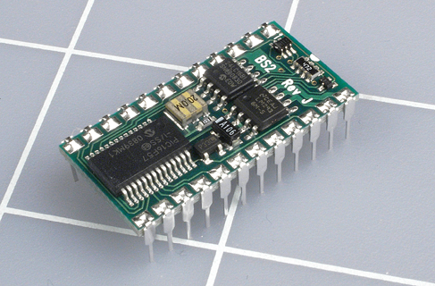
Figure 5-97. The BASIC Stamp microcontroller consists of surface-mounted components on a platform that has pins spaced at 1/10-inch intervals, for insertion in a breadboard or perforated board.
On the downside, you’ll find that everything associated with the BASIC Stamp is a bit more expensive than in the PICAXE world, and the download procedure isn’t quite as simple.
New products such as the Raspberry Pi extend the functionality of a microcontroller to the point where it becomes a real computer. By the time you read this, still more alternatives will be emerging in this turbulent field. Before you commit yourself to learning one of them in detail, I think it’s a good idea to spend a day or two studying the online documentation and forums.
When I am thinking about learning something new, I do Google searches such as:
microcontroller problems OR difficulties
(I would substitute the name of an actual product for “microcontroller” in this search phrase.)
This is not because I am negative by nature. I just don’t want to spend a lot of time on a product that turns out to have unresolved issues.
Unexplored Territory
It’s time, now, for me to do some general summing up.
If you’ve taken the time to complete most of the projects in this book with your own hands, you have gained a very rapid introduction to the most fundamental areas of electronics.
What have you missed along the way? Here are some topics that remain wide open for you to explore. Naturally you should search online if they interest you.
The informal approach of Learning by Discovery that I have used in this book tends to be light on theory. I’ve avoided most of the math that you’d be expected to learn in a more rigorous course on the subject. If you have mathematical aptitude, you can use it to gain a much deeper insight into the way in which circuits work.
We didn’t go very far into binary code, and you didn’t build a half-adder, which is a great way to learn how computers function on the most fundamental level. But in Make: More Electronics, I show you how to do this.
I avoided going deeply into the fascinating and mysterious properties of alternating current. Here again, some math is involved, and just the behavior of current at high frequencies is an interesting topic in itself.
For reasons already stated, I avoided surface-mount components—but you can go into this area yourself for a relatively small investment, if you like the idea of creating fascinatingly tiny devices.
Vacuum tubes were not mentioned, because at this point, they are mainly of historical interest. But there’s something very special and beautiful about tubes, especially if you can enclose them in fancy cabinetwork. In the hands of a skilled craftsperson, tube amplifiers and radios become art objects.
I didn’t show you how to etch your own printed circuit boards. This is a task that appeals only to certain people, and the preparation for it requires you to make drawings or use computer software for that purpose. If you happen to have those resources, you might want to do your own etching. It could be a first step toward mass-producing your own products.
I didn’t cover static electricity at all. High-voltage sparks don’t have any practical applications, and they entail some safety issues—but they are stunningly impressive, and you can easily obtain the necessary information to build the equipment. Maybe you should try.
Op-amps and higher-level digital logic are other topics that I haven’t touched here. However, they are included in Make: More Electronics.
In Closing
I believe that the purpose of an introductory book is to give you a taste of a wide range of possibilities, leaving you to decide for yourself what you want to explore next. Electronics is ideal for those of us who like to do things ourselves, because almost any application—from robotics, to radio-controlled aircraft, to telecommunications, to computing hardware—can be pursued by just one person, working at home, with limited resources.
As you delve deeper into the areas of electronics that interest you most, I trust you’ll have a satisfying learning experience. But most of all, I hope you have a lot of fun.