Chapter 8
Power Transmission
Early internal-combustion engines were lacking in power and torque flexibility, in comparison with the steam engines of the period. With a mechanically connected driving means, it was impossible for the internal-combustion engine to attain the smoothness and flexibility of the steam engine, because the internal-combustion engine depends on a series of quick successive explosions in the cylinder to produce power and torque, and on the momentum stored in a heavy flywheel to keep it operating between explosions. Also, the steam engine was capable of delivering rapid, smooth acceleration of the load to maximum speed within its power range, without pauses or slowdowns for shifting gears, as was required with the internal-combustion engine. All these factors contributed to the development of hydraulic drives for internal-combustion engines.
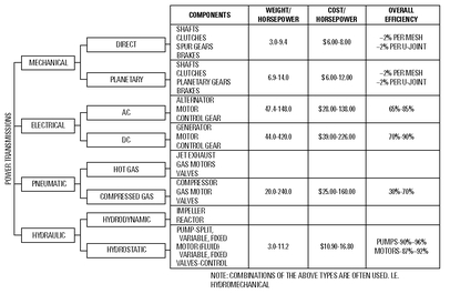
Figure 8-1 shows the various types of power transmissions and their overall efficiency.
Hydraulic Drives
A
hydraulic drive (also called a
fluid drive or
liquid drive) is a flexible hydraulic coupling. It is a means of delivering power from a prime mover to a driven member through a liquid medium—with no mechanical connection. A pioneer type of hydraulic drive (see
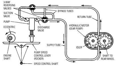
Figure 8-2) was invented and built by H. E. Raabe in 1900. In construction, a separate hydraulic motor (similar to a common gear-type pump) was attached to each rear wheel, thereby permitting differential rotation on curves.
Figure 8-2 A pioneer type of hydraulic drive invented and built by H. E. Raabe in 1900.
In the
Figure 8-1, one of the motors, the connecting piping, the reversing valves, the pump, and the pump drive are shown. In the actual operation of the system, an eccentric on the engine shaft provides an oscillating motion to the rocker that operates the pump, forcing oil through the system as indicated by the arrows in the diagram. If the two reversing valves are turned 90 degrees in unison, the flow of oil and the motion of the car are reversed. Variable speed is obtained by shifting the position of the fulcrum of the rocker, which varies the stroke of the pump. A multi-cylinder pump is used to avoid pulsations and a jerky movement to the car.
Basic Operating Principles
The hydraulic drive mechanism consists of the following three essential parts:
• Driver
• Follower (sometimes called runner)
• Casing or housing
The power from the engine is delivered to the driver. It is then transmitted (flexibly) to the follower through the hydraulic medium.
In actual operation of the hydraulic drive, the power is transmitted from the driver to the follower because of effect of circulation of the hydraulic medium or oil. The circulation of the hydraulic oil is caused by the difference in the centrifugal force set up in the driver and the centrifugal force set up in the follower.
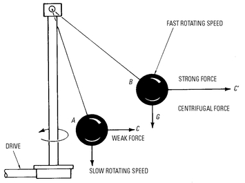
It should be remembered that centrifugal force (see
Figure8-3) is the force that acts on a body moving in a circular path, tending to force it farther from its axis of rotation. Hydraulic oil
does not circulate if both the driver and the follower rotate at the
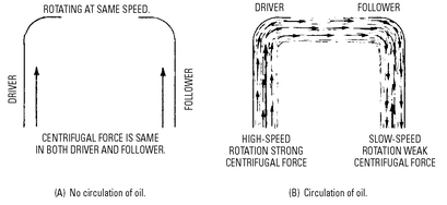
same speed, because the centrifugal force in the driver is equal to the centrifugal force set up in the follower. Hence, the oil does not tend to circulate, because neither force is excessive. This also indicates that the hydraulic oil
does circulate only when the centrifugal force set up in the driver is
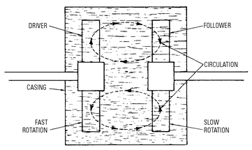
greater than the centrifugal force set up in the follower (see
Figure 8-4). To obtain this condition, it is necessary for the driver to rotate at a higher speed than the follower. That is because the intensity of the centrifugal force depends on the speed of rotation.
Figure 8-3 Centrifugal force as the basic operating principle of the common fly-ball type of engine governor. At slow speed, the ball is forced outward to position A in its circular path. If the engine load decreases, the engine speed increases, and the increased centrifugal force moves the wall outward to position B in its circular path. The increased centrifugal force is indicated by the lengths of the vectors C and C’. In each instance, the downward pull of gravity G is constant and is overcome by centrifugal force. Similarly, in the hydraulic drive, centrifugal force is greater in the high-speed driver than in the follower rotating at a slower speed. This difference in the centrifugal force causes the hydraulic oil to circulate.
Figure 8-4 The basic cause of oil circulation in a hydraulic drive. The centrifugal forces in the driver and follower are opposed, and hydraulic oil does not circulate unless the force in one of the members is greater, the result of increased rotation speed.
Essentially, the driver in the hydraulic drive is a centrifugal pump, and the hydraulic oil circulates in circular paths (see
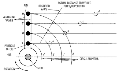
Figure 8-5). In traversing the circular paths during the circulation of the oil, the hydraulic oil particles are forced outward by centrifugal force. The length of the circular path increases for each revolution, which means that the oil particles are accelerated tangentially (tangential acceleration) as shown in
Figure 8-6. This is illustrated by the successive positions
A,
B,
C, and
D of an oil particle as it is forced outward from the hub to the rims of the adjacent vanes of the driver. As shown in the diagram, the distance traveled by an oil particle in one revolution increases as the oil particle moves outward to positions
C and
D. Similarly, the
tangential velocity increases. This means that there is
tangential acceleration, which is indicated by the increasing distances
Aa,
Bb,
Cc, and
Dd from the axis of rotation.
Tangential Acceleration
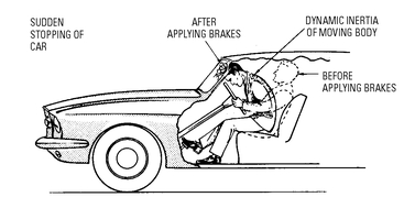
Both tangential acceleration and tangential deceleration require an expenditure of energy (supplied by the engine). Most of the tangentially accelerated oil in the driver is converted at the follower into torque during deceleration. An expenditure of energy is required to tangentially accelerate the oil, because the oil particles press against the vanes of the driver as they move outward. Strictly speaking, the vane presses against the oil particles to overcome the dynamic inertia resulting from acceleration of its tangential velocity as the oil moves outward from the hub to the rim of the vane. Dynamic inertia causes a moving body to remain in a state of uniform motion, unless acted upon by a force that compels it to change that state (see
Figure 8-7).
Figure 8-5 Circular path of hydraulic oil particles in circulating from the driver to the follower. Centrifugal force forces the oil particles outward from the hub to the rim, and they return at the hub.
Figure 8-6 Tangential acceleration as the hydraulic oil particles move outward from the hub to the rims of the adjacent vanes of the driver.
Dynamic inertia enables the hydraulic oil to drive the follower. The hydraulic oil entering the passages formed by the follower vanes possesses both a forward (axial) motion and a lateral (tangential) motion. The lateral or tangential movement of the oil causes the hydraulic oil to press against the leading vane, thereby driving the follower in the tangential direction in which the oil tends to continue to move because of its dynamic inertia.
Figure 8-8 shows a diagram of two adjacent vanes illustrating oil flow from the driver to the follower. The axial movement
A of the oil flow and the tangential movement
T are shown in the diagram. The sideways movement (from driver to follower) is the result of the driver rotating faster than the follower.
Figure 8-9 shows the flow of hydraulic oil resulting from both axial movement and tangential movement. In the diagram, the direction and velocity of axial movement
OA and the direction and velocity of tangential movement
OB represent the sides of the parallelogram
OABR. Then the diagonal
OR represents the direction and velocity of the actual oil flow resulting from the two component movements. Since the diagonal
OR of the parallelogram represents the actual direction of oil flow, the oil strikes the leading vane of the follower at an angle
AOR. The normal thrust
AR on the leading vane of the follower produces torque that tends to rotate the vane. Since the tangential direction and velocity of the oil
OB is equal to the thrust
AR on the vane of the follower, tangential acceleration produces torque that tends to rotate the follower.
Figure 8-8 Sectional diagram (bottom) with a portion of the rims of adjacent vanes cut away (on line AB in upper left), showing the axial movement A and the tangential movement T of hydraulic oil.
Tangential Deceleration
As mentioned, an expenditure of energy is required either to increase the velocity of a moving body or to slow it down (see
Figure 8-10). For example, work is required by a locomotive to increase the speed of a train to its top speed. The kinetic energy (stored capacity resulting from the momentum of the moving body) acquired thereby is expended by applying the brakes to slow the speed of the train. In this instance, the energy is converted to heating of the brake shoes.
Tangential deceleration also produces torque that tends to rotate the follower. On entering the follower, the hydraulic oil is forced (by excessive forward centrifugal force) to flow from the rim to the hub, which decelerates its tangential velocity. In the meantime, the tangential component (see
AR in
Figure 8-9) of the kinetic energy originally possessed by the hydraulic oil on entering the follower is expended against the leading vane to produce torque that tends to rotate the follower. The kinetic energy, in this instance, represents the work necessary to change the body from its actual velocity or state of motion to a state of rest.
Figure 8-9 The flow of hydraulic oil resulting from tangential and axial movements (left); tangential acceleration produces torque which tends to rotate the vane of the follower (right).
Figure 8-11 shows the effect of tangential deceleration. Note that in positions
A,
B,
C, and
D in the follower, the oil particle is moving toward the hub, and that these positions are the same distance from the axis in tangential deceleration as they were in tangential acceleration. This indicates tangential deceleration of the hydraulic oil produces a driving force or thrust on the leading vane of the follower.
Types of Hydraulic Drives
The basic operating principle of the hydraulic drive is used in many different types of transmissions. In all these drives, the two rotating members are the driver and the follower (or runner).
Fluid Drive
Figure 8-12 shows a section diagram showing details of construction of a typical fluid drive. Stamped, pressed, and forged parts are used in construction of the fluid drive. The hubs for the impeller housing and the follower (runner) are forged. The outer housing and the follower disk are made of pressed cold-rolled steel, and the vanes (22 in the impeller and 24 in the follower) are made of stamped cold-rolled steel (see
Figure 8-13). The vanes are assembled permanently onto the impeller and follower disks by spot welds on each vane. The follower disk is welded permanently to the follower hub. The follower is mounted in the impeller on a ball bearing, and is located in the forward portion of the assembly. The follower is supported in the assembly by the transmission drive pinion shaft. A low-viscosity mineral oil is used in the fluid coupling. It provides the lubrication required by the bearing enclosed within the coupling, and the oil pours at the lowest temperature anticipated.
Figure 8-10 Kinetic energy. Work is required by the locomotive to start the load (top), and work is required for the moving cars to stop the load, which tends to remain in motion (bottom). Note that the work required to stop the load is converted to heating of the brake shoes.
As shown in
Figure 8-12, the two rotating elements are the driver and the follower (runner). The difference or
slip in rotating speeds of the two members is approximately 1 percent in average driving conditions at normal speeds over level roads. On a long, difficult pull, the percentage of slip is greater, and it is 100 percent when the car is stopped and in gear with the engine idling.
Figure 8-11 Application of force to the driver to obtain tangential acceleration of the hydraulic oil (upper left); and why tangential deceleration produces torque or a tendency to rotate the follower (upper right). The effect of tangential deceleration is illustrated further in the lower diagram.
Figure 8-12 Construction details of a typical fluid drive.
Following are the chief advantages claimed for a fluid drive:
• The car can be placed in high gear in following normal traffic without declutching or shifting gears.
• The kick-down overdrive in conjunction with fluid drive provides virtually an automatic two-speed transmission in high gear.
• Since the engine does not stall when the car is stopped, declutching is unnecessary.
• A fluid drive dampens engine torsion vibrations.
• Gear shifting or operation of the clutch pedal is eliminated in normal traffic conditions.
• Declutching or shifting out of gear is not necessary in starting the engine.
• The engine can be used as a brake.
Hydraulic Drive
A type of hydraulic drive (called hydramatic by the manufacturer), combined with a fully automatic four-speed transmission, eliminates the conventional clutch and clutch pedal. The automobile is set in motion by merely depressing the accelerator pedal, and the hydraulic drive unit transmits power smoothly and firmly. Motion starts in low gear, shifting successively to second, third, and fourth gears in order. Shifting is dependent on the throttle opening.
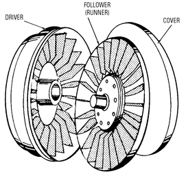
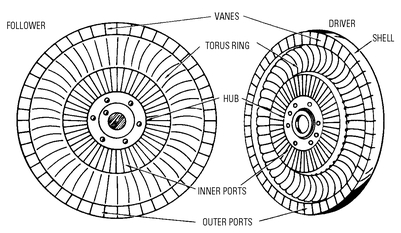
The two rotating members are the driver and the follower (see
Figure 8-14). In construction, both members are made of pressed steel and each contains 48 half-circular divisions called
torus passages .
Figure 8-15 shows hydraulic oil circulation around these passages. When the driver and the follower are turning at the same speed, the hydraulic oil does not circulate. Therefore, there is no torque produced. The oil circulates only when one member rotates at a faster speed. The member that rotates faster becomes the
driver, and the other is the
driven member. Thus, the automobile can drive the engine—in the same manner that the engine can drive the car. If more power is required, the operator depresses the accelerator to provide the engine with more gasoline. This, in turn, increases the speed of the driver; this circulates more hydraulic oil to meet the increased load. The speed of the driver relative to the speed of the driven member is increased, which, in effect, delivers more power to the rear wheels. The automobile cannot begin motion while the engine is idling, because the driver is not rotating at a speed that is fast enough to overcome the static inertia of the car.
Figure 8-14 The driver and follower in a hydramatic drive.
Figure 8-15 Cross-sectional diagram showing circulation of hydraulic oil in the driver and follower (left); circulation of oil in the rotor is illustrated further (right).
Twin-Disk Hydraulic Drive
In the twin-disk hydraulic drive (see
Figure 8-16), two parallel units deliver power to the same drive shaft. The basic parts are: (1) the front driver; (2) twin followers (two followers); and (3) the rear driver. This drive is sometimes called a hydraulic clutch and hydraulic power takeoff.
Figure 8-16 Cross-sectional view of a twin-disk hydraulic drive.
Hydraulic Torque Converter
The torque converter operates on the same basic principle (circulation of the fluid for the transmission of power) as the twin-disk hydraulic drive. However, in the torque converter, a stationary member is placed between the pump and the turbine to change the direction of the fluid. The pump is coupled to the engine. It circulates the fluid. The centrifugal pump imparts velocity to the fluid, which becomes the transmission medium for the power delivered by the engine.
As the fluid is forced against the turbine blades and the blades mounted on the stationary housing, its energy is manifested in the form of torque and speed. As a result of the action of the fluid on the turbine and stationary blades, the engine or input torque is multiplied increasingly as the speed of the output shaft is reduced. The engine cannot be stalled, because there is no mechanical connection between the engine and the turbine.
In construction of the hydraulic torque converter (see
Figure 8-17), two sets of stationary blades are located between the three stages of the turbine. The stationary blades that redirect the flow of fluid are mounted in the stationary housing. The housing is fastened either to the engine or to a solid base. The blades cannot move when the fluid is forced against them. Therefore, the fluid flow is redirected and the resistance of the fluid to this change. The result is torque multiplication or an increase in torque at each turbine stage. This also comes with a corresponding decrease in speed of the output shaft.
Figure 8-17 Basic operating principle of a hydraulic torque converter.
As shown in
Figure 8-18, the curve indicates the output torque obtained with an engine delivering 500 lb-ft of torque at 1800 rpm, which is the broad, nearly flat curve, peaking at approximately 85 percent. As the output shaft-speed approaches nearly two-thirds, the speed of the engine (depending on losses in the system), the engine torque, and the converter torque become equal.
Hydrostatic Transmission Systems
A hydrostatic transmission (or hydraulic displacement-type transmission ) is a combination of two interconnected positive-displacement units: a pump and a motor. This is in contrast to the hydrodynamic type of transmission.
The pump may be located at a considerable distance from the motor, or the two units (pump and motor) may be combined in a single housing. The rotary hydraulic pump transforms mechanical energy into fluid pressure energy. The high-pressure oil is then delivered to a rotary hydraulic motor. In the motor, the fluid pressure energy is transformed into mechanical energy. The oil flows from the pump to the motor. It then flows from the motor to the pump.
Figure 8-18 Performance characteristics of a typical hydraulic torque converter.
This type of transmission has a number of advantages:
• Output shaft speed can be maintained at a constant speed for a variable-speed input.
• Speed and direction of the output shaft can be controlled accurately and remotely.
• Constant power output can be maintained over a wide range of speeds.
• Automatic torque control at the output shaft can be maintained.
• Output shaft speed can be varied in minute steps.
• Output shaft can be reversed quickly and without shock.
• Power consumption can be kept at a low level.
• Automatic overload protection can be maintained.
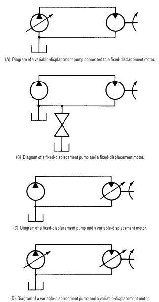
Figure 8-19 illustrates the basic circuits for standard hydraulic transmissions. In
Figure 8-19(a), a variable-displacement pump can be connected to a fixed-displacement motor. If the workload is constant, a variation in the output shaft speed results in an almost constant output torque and in variable power. Constant-torque transmissions are used on machine tool feeds and conveyors.
Figure 8-19 Basic circuits for standard hydraulic transmission.
In
Figure 8-19(b), a fixed-displacement pump can be connected to a fixed-displacement motor. If a flow control is placed in the line to vary the rate of oil flow to the motor, and if the load on the output shaft is constant, the torque is constant and the power can be varied with the speed.
In
Figure 8-19(c), a fixed-displacement pump is connected to a variable-displacement motor. If it is desired to maintain constant power output as the output speed is varied (as in winders and machine tool spindle drives, for example), the displacement of the motor can be varied. Then the output torque decreases as the speed increases.
In
Figure 8-19(d), a variable-displacement pump is connected to a variable-displacement motor. This combination can provide variations in output shaft speed, torque, and power characteristics of hydraulic transmissions.
Table 8-1 shows a summary of characteristics of hydraulic transmissions.
Table 8-1 Summary of Characteristics of Hydraulic Transmissions
The Dynapower transmission system (see
Figure 8-20), manufactured by Hydreco, a unit of General Signal, is designed to produce constant horsepower, constant torque, and constant speed within close tolerances. Reversibility, instantaneous response, step-less speed variation, dynamic braking, and built-in overload protection make the drive extremely versatile.
The Dynapower hydrostatic transmission utilizes a closed hydraulic system. The inlet and discharge ports of a variable-displacement axial piston pump are connected to the discharge and inlet ports of an axial piston motor (fixed or variable) by hose or tubing.
Figure 8-20 Dynapower hydrostatic transmission system. Dynapower is the registered trademark of the New York Air Brake Company for its hydrostatic transmission and related components. The transmission system consists of a closed hydraulic system.
(Courtesy Hydreco, Div. of General Signal)
The filter, reservoir, charge pump, and valves are also part of the transmission. The charge-pump and check valves are located in the cover of the pump, and the other valves are built into the cover of the motor. This feature minimizes the plumbing and hardware required in the system.
In operation, the hydraulic oil flows from the pump (see
Figure 8-21) to the motor through the main system lines and causes the motor to rotate when the variable cam in the pump is moved from neutral position. The discharge oil from the motor returns directly to the pump inlet. The motor reverses when the cam in the pump is moved through neutral to the opposite direction.
Oil is supplied to the charge pump by a line direct from the reservoir, and it discharges through one of the two check valves to the low-pressure side of the system. This provides makeup oil and inlet pressurization to the closed system. Pressurization is maintained by the low-pressure relief valve, which also relieves excess oil from the charge pump back to the reservoir.
The system is protected from over-surges or extremely high starting pressures by the pilot-operated high-pressure relief valve. The valve discharges to the low-pressure side of the system, to prevent depletion of oil in the closed system.
Figure 8-21 Cutaway view showing the basic parts of the pump in a Dynapower hydrostatic transmission system.
(Courtesy Hydreco, Div. of General Signal)
A pressure-actuated shuttle valve directs both high pressure and low pressure to the respective relief valves. The shuttle valve moves toward the low-pressure side when one line is high pressure. This, in turn, ports the high pressure to the high-pressure relief valve and the low-pressure side to its relief valve. The shuttle valve is also used to direct high-pressure relief valve discharge to the low-pressure side of the system.
The output of standard production machines can be made suitable to specific needs by selecting the correct control. A wide variety of interchangeable types of controls are available. Following are controls used on the Dynapower hydrostatic transmission system:
• Manual—The cam angle is determined by the position of a simple control rod linked directly to the pump or motor cam. A hand wheel on a threaded rod is attached for fine positioning of the pump or motor cam.
• Low-pressure hydraulic control—Charge pump pressure (approximately 100 psi) is utilized by the control to position the cam and to provide over-center travel. The actuating arm of the control requires 2 to 4 pounds of effort for its operation.
• Input torque limiting control—Stalling of the engine is prevented under all conditions.
• Constant-speed control—Input speeds can be varied while maintaining constant output speed. The output varies with demand.
• Pressure-compensated motor control—Motor speed is increased automatically by decreasing the cam angle in the motor, as pressure decreases. Conversely, by increasing the cam angle in the motor as the pressure increases, lower speed and higher output torque are obtained.
• Pressure-compensator pump control—This control has been made necessary by the hydrostatic transmission, although it is not normally a component of the system itself. Full flow (maximum cam angle) is maintained until a predetermined system pressure is attained. The flow is then halted while the pressure is maintained. Flow resumes to compensate for system leakage (or at system demand). A manual cutoff of flow and pressure can be used to reduce wear and horsepower demand on the system.
The transmission as shown in
Figure 8-22 is designed to operate at speeds up to 4200 rpm and pressures up to 4500 psi. This transmission provides a smooth, infinite control of speed, direction, and dynamic braking with the touch of a single lever control. Use of this type of transmission is found on garden tractors, snowmobiles and other pleasure vehicles, materials-handling equipment, and on other applications requiring variable speed.
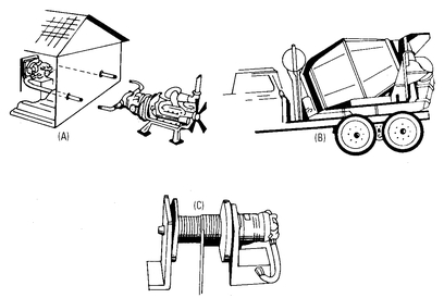
Hydrostatic hydraulic drives have been developed for many mobile and industrial applications (see
Figure 8-23). These drives are used on machine tools, centrifugal pumps, production machines, winches, paper and textile rolls, surface and center windows, conveyors, reels, calendaring equipment, printing presses, fans and blowers, agitators, mixers, disintegrators, materials-handling machines, plastic extruders, and dynamometers.
Figure 8-23 Application of the hydrostatic transmission: (a) remote drive; (b) mixing-drum drive; and (c) winch drive.
(Courtesy Hydreco, Div. of General Signal)
Hydraulic Adjustable-Speed Drive
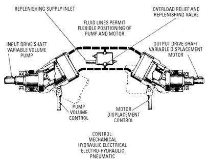
The Vickers hydraulic adjustable-speed drives (see
Figure 8-24) are also based on the hydrostatic principle. Power is transmitted by means of an electrically driven variable-displacement pump, providing pressure and a flow that is converted to usable power by a hydraulic motor (see
Figure 8-25). The hydraulic fluid is returned to the pump, completing the cycle without entering a tank or sump. In the diagram, both the pump and the motor are fitted with stroke controls. The pump control can be adjusted to obtain an output-speed range from minimum to intermediate speed, with constant torque throughout the range. The fluid motor can be adjusted to obtain speeds above this range (with a decrease in torque).
Figure 8-24 Vickers hydraulic adjustable-speed drives are based on the hydrostatic principle.
(Courtesy Sperry Vickers, Div. of Sperry)
Figure 8-25 Diagram of a hydraulic adjustable-speed drive. Both the pump and the motor are fitted with stroke controls.
(Courtesy Sperry Vickers, Div. of Sperry Rand Corp.)
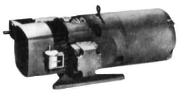
Hydraulic adjustable-speed drives provide either a direct or an indirect drive for many industrial applications, including hoists and winches, food machinery, and processing equipment. The adjustable-speed transmission shown in
Figure 8-26 is used on many fractional-horsepower machinery drives; with constant output torque characteristics, it can be started under full-load torque from zero rpm in either direction of rotation. Overload protection permits stalling of the unit without damage, and the output speed is smooth and step-less over its entire range.
Farm Tractor Applications
The hydraulic transmission is used extensively on farm tractors. A large-capacity variable-displacement pump is used to provide remote control of equipment (see
Figure 8-27). The pump is also used to provide power steering and power braking, which have become standard equipment on many farm tractors. In addition, remote cylinders, a three-point hitch, and a power-differential lock are all parts of the hydraulic system.
Figure 8-26 An adjustable-speed transmission.
(Courtesy Sperry Vickers, Div. of Sperry Rand Corp.)
On tillage operations, instant shifting (without stopping) permits ground travel speeds to be maintained. A constant load on the engine is retained, and the engine rpm stays within the operating range (for greater economy and efficiency). Power takeoff equipment can be kept working at full capacity when harvesting heavy crops by merely moving the shift lever to maintain the proper ground speed (including neutral position).
Action that requires direction reversal can be provided without clutching—and without stopping. This is ideal for operations that require constant changing in direction (such as stacking and loading).
Figure 8-28 shows a large farm tractor that makes use of a considerable amount of hydraulics. It has hydrostatic power steering, hydrostatic power wet disk brakes, a hydraulic power-actuated clutch, and even a hydraulically adjusted seat.
Figure 8-27 A single-pump hydraulic system can be used on a farm tractor to provide power for steering, braking, position control for a three-point hitch, and a power-differential lock.
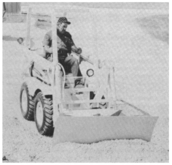
Figure 8-29 shows a loader that finds many applications in industry. This machine has a hydrostatic four-wheel drive with infinitely variable zero to 8 mph forward-reverse ground speeds. The unit can be slowed to a very low speed, reversed, or accelerated to full speed in either direction without changing engine rpm, and without having to change gears.
On each side of the loader is a hydrostatic drive pump that eliminates chattering or hopping at extra low speeds.
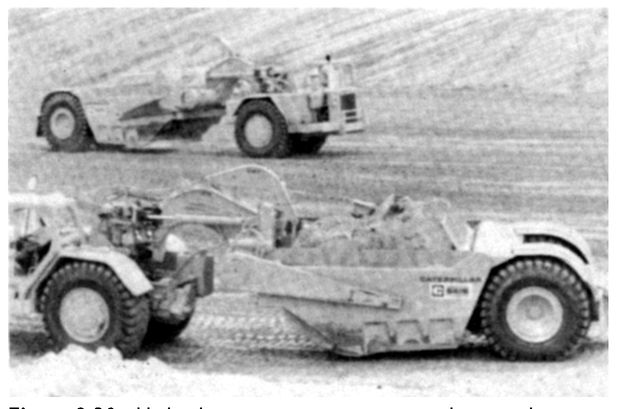
Figure 8-30 shows an earthmover that makes use of a very large amount of hydraulic equipment.
Pumps for Robots
In recent years, more and more manufacturing concerns have been using industrial robots, and reliable pumps are crucial to the success of such machinery. When a robot calls for, say, 10 gallons of oil, a pump must be able to deliver it instantaneously, to avoid operational efficiency or damage.
Robots
Robots need some type of power to cause them to function. To make the arm or any other part of the system move, it is necessary to develop the power in a usable form and in some type of readily available unit.
Figure 8-29 Skid steer pay-loader.
(Courtesy Caterpillar Tractor Co.)
Figure 8-30 Hydraulic equipment is important on large earth-moving machinery.
Following are three are ways used to power a robot and its manipulators:
• Hydraulic systems
• Pneumatic systems
• Electrical systems
Of course, electricity is used to make the pneumatic and hydraulic systems operate. However, there is also an all-electric type of drive available in the form of electric motors being directly attached to the manipulator or moving portion of the robot.
Hydraulics
Of the three types of drive systems for robots, the hydraulic system (see
Figure 8-31) is capable of picking up or moving the heaviest loads. That is why it is used. The hydraulically powered robot is ideally suited for spray painting where electric systems can be hazardous.
The automobile uses a hydraulic system for braking. As the brake pedal is depressed, it puts pressure on a reservoir of liquid that is moved under pressure to the brake cylinders. The brake cylinders then apply pressure to the pads that make direct contact with the rotors that are attached to the four wheels. By applying the pressure to the pads in varying amounts, forward motion of the car is either stopped or slowed, as desired. The hydraulic system used for the robot is similar to the baking system of an automobile.
Hydra is the Greek word for water. However, oil, not water, is used in robot drive systems. (Some water-based hydraulic fluids are used in foundry and forging operations.) This oil presents the pressure to the correct place at the right time in order to move the manipulator or grippers. Hydraulic pressure in a hydraulic system applies force to a confined liquid. The more force applied to the oil, the greater the pressure on the liquid in the container.
Pressure
The force applied to a given area is called pressure. Pressure is measured in pounds per square inch. Pressure can be abbreviated as lb/in2 or psi.
The SI metric unit for pressure is the pascal. The pascal is one newton per square meter (newton is the unit of force). Because the pascal is such a small unit, kilopascals (kPa) and megapascals (MPa) are used. For example, a typical automobile tire pressure is usually not more than 35 psi.
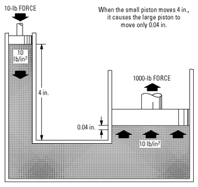
There are several ways to develop the pressure in a robot. The pressure developed in a hydraulic circuit in terms of how much push or force is applied per unit area (see
Figure 8-32). Pressure results because of a load on the output of a hydraulic circuit or because of some type of resistance to flow. A pump used to create fluid flow through the piping to the point where it causes movement of the gripper or manipulator of the robot. A weight can also be used to generate pressure.
Figure 8-32 Hydraulic pressure changes. The 20-pound force can cause 1000 pounds to be lifted, but notice the distance traveled of both the force and the object being moved.
One of the disadvantages of using the hydraulic system is its inherent problem with leaks. While fluid is under pressure, it has a tendency to seek the weakest point in the system and then run out. This means that each joint along the piping must be able to withstand high pressure without leaking. It also means that the moving part of the robot (the manipulator) must be able to contain the fluid while it is under pressure. In most cases, the O-rings are not able to contain the fluid and leaks occur. O-rings are very important in sealing the moving end of the manipulator or terminating end of the fluid line. This is one of the maintenance problems associated with robots used for picking up heavy objects. The hydraulics system is used to pick up the weight. It is then typically dependent on industrial air pressure lines equal to at least 700 kPa. One lb/in2 is equal to 6.896 kPa, and 1 kPa is equal to 1.45 lb/in2.
The pressure applied to a hydraulic system is in terms of how much push or force is applied to a container of oil, as shown in
Figure 8-32. There are several ways to develop the pressure needed in a robot.
The pressure developed in a hydraulic circuit is in terms of how much push or force is applied per unit area. Pressure results because of a load on the output of a hydraulic circuit or because of some type of resistance to flow.
A pump is used to create fluid flow thorough the piping to the point where it causes movement of the gripper or manipulator of the robot. A weight can also be used to generate pressure.
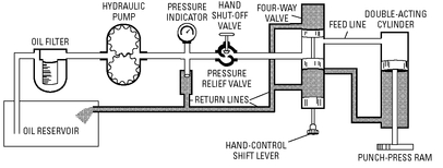
Pressure build-up in a hydraulic system can be a problem. It is sometimes necessary to prevent its continuing to increase beyond the capacity of the pipes and containers. That is where a relief valve becomes important. A relief valve is used as an outlet when the pressure in the system rises beyond the point where the system can handle it safely. The valve is closed as long as the pressure is below its design value. Once the pressure reaches the point of design for the relief valve, it opens. Then the excess fluid must be returned to the reservoir or tank. This means a relief valve and the return of the fluid to tank must be part of the system.
Hydraulic systems need filters to keep the fluid clean. Even small contaminants can cause wear quickly. The filter must take out contaminants that measure only microns in size. The filters must be changed regularly to keep the fluid and system in operating condition.
Pressures of several thousand psi are not uncommon in the operation of a robot. This means that a leak as small as a pinhole can be dangerous. If you put your hand near a leak, it is possible that the fluid being emitted though the hole would cut off your hand before you feel it happen. However, this will not occur at pressures below 2000 psi. High pressures are very dangerous.
Additional volume for the operation of the robot may be obtained by pressuring the surge tank with a gas. An accumulator can only be charged to the main system pressure. In some cases, the robot will require a large volume of fluid for rapid motion than the pump alone can provide. In other cases, a surge tank on the high-pressure side of the line is charged with a gas in a flexible container. This flexible container is inside the tank and expands. High pressure of the fluid compresses the gas when there is excess pressure available. Then, when the system needs the fluid for the rapid motion, the pressure drops slightly and the gas in the tank expands to force the extra fluid into the system.
Hydraulic motors mounted on a manipulator are operated by signals from a transducer. This is either to open the valve for a given length of time, or to keep it closed. The control system is necessary to do it. Hydraulic motors and cylinders are compact and generate high levels of force and power. They make it possible to obtain exact movements very quickly (see
Figure 8-33).
Figure 8-33 Hydraulic motor. Pressure on the hydraulic fluid causes the motor to turn in a counter-clockwise direction. Reversing the direction of fluid flow reverses the direction of the motor rotation.
Pumps
The hydraulic system must have a pump to operate. The pump converts mechanical energy, usually supplied by an electric motor.
Hydrostatic pumps are further classified into gear pumps and vane pumps. These pumps are called on to deliver a constant flow of fluid to the manipulator. The gear pump produces its pumping action by creating a partial vacuum when the gear teeth near the inlet unmeshes. It causes fluid to flow into the pump to fill the vacuum. As the gears move, they cause the fluid or oil to be moved around the outside of the gears to the outlet hole at the top. The meshing of the gears at the outlet end creates a pushing action that forces the oil out the hole and into the system.
The vane pump gets its name from its design, as does the gear pump. The vanes cause the fluid to move from a large volume area to a small volume area. By pushing the fluid to a smaller area, the pressure on the fluid increases since the fluid itself it not compressible (see
Figure 8-34).
Figure 8-34 Vane-type pump/motor. Note also that this hydraulic pump can be used as a motor when driven by the hydraulic fluid under pressure.
A vane pump can be used to supply low-to-medium pressure ranges, capacity, and speed ranges. They are used to supply the manipulator with the energy to lift large loads. Pressures can reach as high as 2000 psi with about 25 gallons of fluid per minute (gpm) moving in the system.
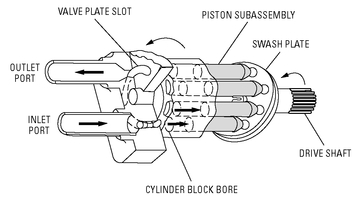
Piston-type rotary devices are also used to increase the pressure in a hydraulic system. The pistons retract to take in a large volume of fluid and then extend to push the fluid into the high-pressure output port. There are usually seven or nine cylinders. These vary with the different configurations of machines. The inline piston pumps are good for robot applications. They have a very high capacity, and their speed ranges are from medium to very high. Pressures can get up over 5000 psi (see
Figure 8-35).
Variable-displacement piston pumps have been used well in such operations. The units, also called atmospheric inlet piston pumps, come in a variety of designs and capacities, but they all work basically the same way. A sensor in the pump senses when oil or other liquid is required and is engineered to deliver it instantly. In other words, the pump senses a pressure drop and responds.
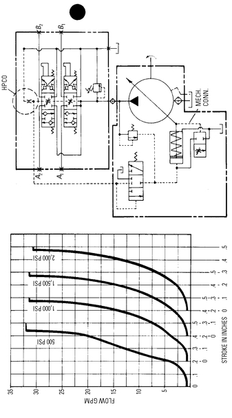
One such pump, which also incorporates sound reduction features, is the Quietpak from Hydreco, a division of General Signal. It uses a standard C-face 1780 electric motor; variable pump flow is available to 30 gpm with a variety of controls, including pressure compensation, load sensing, and horsepower control. In fuel displacement systems, flows to 50 gpm are available with pressures to 3,000 psi. Flow control valves are available to suit application requirements.
Figure 8-36 shows the circuit.
CCS Systems
Hydreco also makes a so-called CCS system, which is a hybrid of closed-center and flow-demand systems. It has the advantages of both. It consists of an elemental circuit (see
Figure 8-37) that includes a parallel control valve and an atmospheric inlet variable-displacement pump with a control mounted on it. Fluid pressure on the pump control will reduce its fluid delivery.
The CCS system works simply. For example, a tractor/ digger/loader hydraulic system will have a loader and a backhoe valve. The two control valves (parallel or tandem) can be plumbed in parallel while maintaining the signal circuit in series. Regardless of the number of valves, there will be only one signal line for each pump (auxiliary valves may also be added). A steering valve, for example, could be supplied from a priority valve, which could include the ability to limit pump stroke if only the steering is in use. This is done by allowing partial signal flow to continue through the system while steering. The balance of the signal flow could be restricted by an implement valve downstream, urging the pump to increase flow.
The system, according to Hydreco, works very well in machines where contact flow is not a requirement. Indeed, the longer the period between full flow, the more appropriate the CCS feature. Equipment such as excavators, backhoes, and cranes are good candidates for this system.
Summary
A hydraulic drive (also called fluid drive or liquid drive) is a flexible hydraulic coupling. It is a means of delivering power from a prime mover to a driven member through a liquid medium—with no mechanical connection.
The hydraulic drive mechanism consists of three essential parts: the driver,) follower, and casing (or housing). The power from the engine is delivered to the driver. It is then transmitted (flexibly) to the follower through the hydraulic medium.
Centrifugal force acts on a body moving in a circular path, tending to force it farther from its axis of rotation. For hydraulic oil to circulate, it is necessary for the driver to rotate at a higher speed than the follower, because the intensity of the centrifugal force depends on the speed of rotation.
Both tangential acceleration and tangential deceleration require an expenditure of energy (supplied by the engine). Most of the tangentially accelerated oil in the driver is converted at the follower into torque during deceleration. Any expenditure of energy is required to tangentially accelerate the oil, because the oil particles press against the vanes of the driver as they move outward.
The Dynapower hydrostatic transmission system is designed to produce constant horsepower, constant torque, and constant speed within close tolerances. Reversibility, instantaneous response, step-less speed variation, dynamic braking, and built-in overload protection make the drive extremely versatile.
Hydrostatic hydraulic drives have been developed for many mobile and industrial applications. These drives are used on machine tools, centrifugal pumps, production machines, winches, paper and textile rolls, surface and center winders, conveyors, reels, calendaring equipment, printing presses, fans and blowers, agitators, mixers, disintegrators, materials-handling machines, plastic extruders, and dynamometers.
Hydraulic adjustable-speed drives are also based on the hydrostatic principle. Either a direct or an indirect drive is provided for many applications (including hoists and winches, food machinery, and processing equipment).
The hydraulic transmission is also used extensively on farm tractors. The hydraulic system is used to provide remote control of equipment, power steering, and power braking. Action that requires direction reversal can be provided without clutching—and without stopping. This is ideal for operations that require constant changing in direction (such as stacking and loading).
Review Questions
1. What is the basic operating principle of a hydraulic drive?
2. What are the essential parts of a hydraulic drive mechanism?
3. What conditions are necessary for hydraulic oil to circulate in a hydraulic drive?
4. Why is a torque a result of both tangential acceleration and tangential deceleration of the hydraulic oil?
5. List the advantages of a fluid drive.
6. How does construction of the torque converter differ in construction from the other hydraulic drives?
7. List the advantages of the hydrostatic transmission.
8. List six typical applications of the hydrostatic transmission.
9. List the advantages of the hydraulic transmission for farm tractor applications.
10. What is another name for a hydraulic drive?
11. What is dynamic inertia?
12. What is kinetic energy?
13. What are the two rotating elements in a fluid drive?
14. What does declutching mean?
15. What is a torque converter?
16. What are the two interconnected positive displacement units in a hydrostatic transmission?
17. Draw the diagram for a fixed displacement pump and a variable displacement motor.
18. What type of transmission uses a closed hydraulic system?
19. What type of transmission does the cement mixer-drum drive utilize?
20. Where are hydraulic adjustable-speed drives used?
