Chapter 12
Hydraulic Control Valve Operators
Chapter 11 discussed the various control valves that are used in hydraulic systems. A means of operating these control valves must be provided if they are to function. In most instances, pressure controls and flow controls utilize valve operators that are different from those used on directional controls. In general, many different types of valve operators are available as standard equipment for directional control valves. It is important to select a suitable valve operator, because a poor choice may lead to problems in creating and maintaining the desired efficiency and controllability in a given fluid system.
Pressure-Control Valve Operators
Pressure-control operators are made in relatively few general types, including the following:
• Direct-acting screw
• Direct-acting cam roller
• Offset cam roller
• Solenoid
• Pilot types
Nearly all types of hydraulic pressure-control valves use a
screw-type operator for setting the correct spring tension at which the valve is to function.
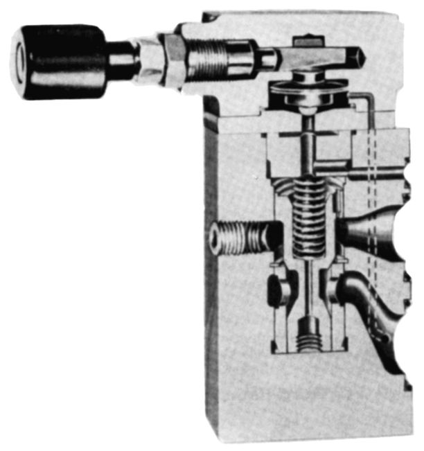
Figure 12-1 shows a combination of screw and sliding cam operators used on a pressure control. As the screw is advanced, the disk spring is compressed, that provides very accurate control over a wide range of flows.
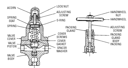
Figure 12-2 shows a direct-acting spring-operated hydraulic relief valve. As the screw-type operator is advanced, spring tension is placed on the spot to increase the operating pressure of the system.
The direct or offset cam roller type of operator is often employed on valves for special applications. For example, this type of operator on a relief valve may be advantageous if a considerable increase in pressure must occur at a given point in the travel of the piston in a cylinder. At that point, a cam can be placed on the machine table or other moving member. At the correct position, the cam depresses the cam-roller-type of operator on the relief valve, causing an increase in operating pressure.
Figure 12-1 Pressure control that uses a combination of screw and sliding cam operator.
The cam-type operators are also found on hydraulic pressure-relief valves used for testing applications where the cams have an extremely shallow angle. The cam roller is depressed gradually, and pressure readings are recorded. Solenoid operators are sometimes used on relief valves.
Flow-Control Valve Operators
In nearly all instances, the flow-control valve operator (in hydraulic systems) utilizes a screw-type or threaded mechanism to open and to close the control orifice in the flow control valve. The screw-type mechanism may be in the form of a needle with slots, as shown in the diagram of the hydraulic valve in
Figure 12-3, which is used for pressures up to 3000 pounds per square inch. After the correct flow is achieved, the needle is locked in position by means of a locknut.
Figure 12-2 Hydraulic pressure-relief valve with a screw-type operator.
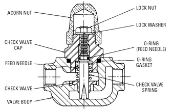
A screw-type mechanism in the form of a needle is used in the low-pressure hydraulic flow control valve shown in
Figure 12-4. The needle in the valve is installed in such a way that the major diameter cannot be backed out beyond the retaining pin (a safety feature).
Figure 12-3 A hydraulic flow-control valve with a screw-type operator.
Figure 12-4 Screw-type operator used in a speed- or flow-control valve.
Screw or threaded mechanisms may be equipped with a hand wheel, a micrometer-type knob, a locking device, or some other device for controlling it.
In
Figure 12-5, the valve operator consists of a throttle mechanism that is so machined that rotating it in one direction decreases the size of orifice
B and rotating it in the opposite direction increases the size of orifice
B. The size of orifice
B determines the amount of flow that passes through the valve. To adjust the speed of the actuator, the throttle is manually rotated.
Directional Control Valve Operators
Directional control valve operators can be classified in a number of different categories, and each category may consist of several different types of operators. Some of these categories are manual, solenoid, mechanical, automatic-return, and pilot operators. Various combinations of these different types of valve operators are also available.
Manual Operators
In most instances, the manual type of valve operator is considered to be the most positive and least expensive. The manual-type operator is actuated by means of the hand, foot, or some other part of the body.
Figure 12-6 shows a
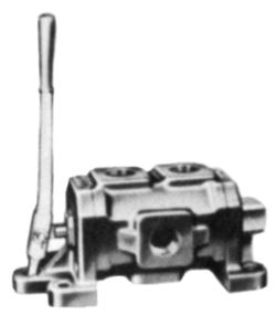
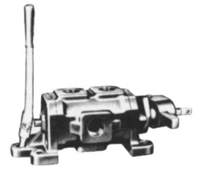
hand-type operator for a hydraulic directional control valve. The hand-type valve operator must be rugged, because a worker often uses a wrench or a piece of bar stock, instead of a hand, to actuate the valve operator.
Figure 12-5 A flow-control and check valve. This series incorporates an integral check valve consisting of a poppet (1), spring (2), and seat (3). The check valve permits reverse free flow from the valve outlet to its inlet port, bypassing the flow-controlling elements.
(Courtesy Sperry Vickers, Div. of Sperry Rand Corp.)
Figure 12-6 A hydraulic directional control valve with a hand-type operator.
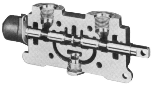
Figure 12-7 shows a stem-operated directional control valve that is used for hydraulic service. This valve is used for controlling and directing flow to double-acting cylinders requiring push, pull, and hold power action. It is also used to start, stop, and reverse fluid motors requiring rotation in either direction. Various types of connectors can be attached to the stem.
Knee-type operators are sometimes utilized, especially on pneumatic directional control valves. These valves can be operated easily when the worker is in a sitting position, thereby freeing the hands for positioning of the work, and so on. If there is a possibility that the worker’s hands may be endangered, the foot- or knee-type operators should be replaced with a hand-type operator in a no-tiedown circuit.
(Courtesy Commercial Shearing, Inc.)
The hand-type operators may be of the spring-offset type, the spring-centered type, or the detent type.
When the
spring-offset valve operator (see
Figure 12-8) is used, a worker is required to keep a hand on the operator until the direction of flow within the valve is changed. When the operator is released, it shifts automatically to its original position.
Figure 12-8 A two-way hydraulic valve with a sliding-spool flow director.
When the
spring-centered valve operator (see
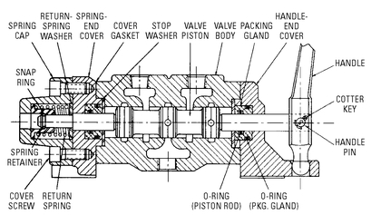
Figure 12-9) is used, a worker must apply force to the handle in either outward position to prevent the handle from returning to the neutral position. When a
detent on the valve operator is used to locate and to hold the spool position, a worker needs only to move the handle until the detent engages (see
Figure 12-10). The handle remains in place until it is moved to another position. Detents are used in two-position and three-position directional control valves.
A directional control valve sometimes requires two valve operators; one of the valve operators is used to shift the valve spool manually in one direction, and the other valve operator is used to reverse the valve spool by means of a solenoid or some mechanical means. With this arrangement, a worker can move some distance from the directional control valve and perform another task while the fluid power equipment is going through its normal operating cycle.
Figure 12-11 shows a hydraulic four-way directional control valve in which the spool is reversed by mechanical means.
Figure 12-9 Spring-centered hand-type operator used on a hydraulic directional control valve assembly.
Solenoid Operators
The solenoid operators consist of the direct-acting solenoid and the solenoid pilot operators. Where direct-acting solenoids are employed, as shown in
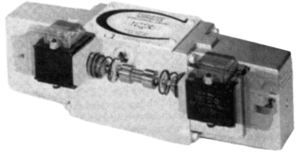
Figure 12-12, the solenoid plunger acts directly against the end of the valve spool in order to shift it.
The large direct-acting solenoid operators cause considerable noise when they are energized, because of the weight of the solenoid plungers. These large operators are not generally employed on high-cycling operations, because of the harsh and severe impact.
Solenoid operators are available in various voltages (such as 115 volts, 230 volts, and so on) for alternating current (AC). In most instances, they are suitable for continuous duty. This means that the solenoid coil may be energized for an indefinite length of time. Solenoids of this type are also available for direct-current (DC) applications and are usually equipped with a cut-out mechanism, often referred to as a mouse-trap. Direct-current solenoids normally are not recommended for continuous service.
The two-position directional control valves that use a direct-acting solenoid operator on one end of the valve and a spring-return type of operator on the other end of the valve are widely used in hydraulic service. This eliminates one solenoid, thus reducing the cost of the control valve. The combination is commonly used in the design of fail-safe circuits. A disadvantage is that the solenoid plunger works against the spring, and it must be kept energized to maintain the spool in position against the spring. Where two direct-acting solenoid operators are used (except on three-position spring-centered valves), the solenoid needs only to be energized for a very short period in order to shift the valve spool. A solenoid operator that uses the mechanical linkage can also use a spring-return operator. Here again, when the spool is working against the spring, the solenoid must be kept energized.
Figure 12-10 Cutaway of a hand-type valve operator with detent.
Figure 12-11 A hydraulic four-way directional control valve with a mechanical reversing mechanism.
(Courtesy Logansport Machine Co., Inc.)
Figure 12-12 Directional control valve with two direct-acting solenoid operators.
(Courtesy Continental Hydraulics)
When a solenoid coil is energized, the plunger must be seated immediately. Otherwise, the inrush current quickly burns out the coil. If dirt becomes lodged between the plunger head and the seat, a malfunction may result. In a double-solenoid valve, if both solenoids are energized at the same time, at least one of the coils may be burned out.
Solenoid pilot operators are common, and, in most instances, they are quite inexpensive. They are compact and require only a small space. The inrush and holding currents are quite low (for example, 0.290 ampere inrush current and 0.210 ampere holding current for 115-volt, 60-hertz current). These operators are available for either AC or DC.
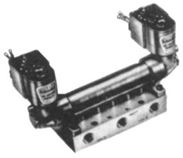
Solenoid pilot operators are available as a complete two-way or three-way valve (see
Figure 12-13) used to control pilot-operated valves or as a subassembly. Solenoid pilot operators are available with explosion-proof housings for use in hazardous locations.
Figure 12-13 A solenoid pilot operator for a directional control valve.
(Courtesy Schrader Div., Scovill Mfg. Co.)
Mechanical Operators
Mechanical operators on directional control valves play an important role on automatic equipment. The most commonly used mechanical operators are the direct-acting cam-roller type (see
Figure 12-14), the toggle lever type (see
Figure 12-15), and the pin type (with or without threaded end).
In the direct-acting cam-roller type of operator, more force is usually required to depress the roller, since it is acting against a spring. The angle on the cam should not be too abrupt, to avoid placing an excessive side load against the cam roller and the bearing in the valve cover.
The direct-acting cam-roller type of operator is found on some of the smaller directional control valves, but it is more commonly used on the larger, more rugged valves for hydraulic service. This type of operator requires a rather short stroke to complete an actuation. The cam roller should not be over-stroked, although some of these valves provide for a small amount of over-travel. The cam is usually attached either to a machine table or to the piston rod of a cylinder. If it is attached to the piston rod of a cylinder, the rod should be supported near the contact point to eliminate deflection of the piston rod. Rotary cams are often used to actuate the cam roller.
The toggle-lever type of operator requires only slight effort to actuate. An inexpensive trip mechanism can be employed. This may be attached to a machine slide, to a feed mechanism, to a piston rod of a cylinder, or to some other moving mechanism. A work piece moving down a conveyor can be used to trip the toggle mechanism.
Return-type operators for directional controls can be of the spring type. The spring returns the spool or flow director to the neutral position, as in a three-position directional control valve. Or, it may return the spool or flow director to the end opposite the spring, as in a two-position directional control valve.
Figure 12-9 shows a valve in which the spring is returned to the neutral position when the spring is released. The spring-return type of operator is used in conjunction with manual, solenoid, mechanical, and pilot types of operators.
Pilot Operators
Pilot types of operators are of the direct acting, bleed, or differential types, and they are found on valves where high cycling, safety interlocks, and automatic sequencing are required, as shown in
Figures 12-16 to
12-18. A direct-acting pilot operator used on a four-way hydraulic control valve is shown in
Figure 12-16. The medium that actuates the pilot operator is hydraulic fluid. To provide for better control of the spool as it shifts, chokes are often employed between the pilot operator and the spool. If two direct-acting pilot operators are employed (one at each end of the spool assembly), two chokes (see
Figure 12-17) are usually used. Adjustable orifices in these chokes are controlled by a needle, and, in some instances, one choke may be set differently from the other choke, so that the spool shifts faster in one direction of travel.
Although most hydraulic directional control valves that use direct-acting pilot operators make use of hydraulic fluid as the medium for shifting the main valve spool, more applications are now being found for compressed air as the shifting medium. There are several advantages to using compressed air as the medium. The controls that direct the fluid to the direct-acting pilot operators are less expensive, are more compact, and are manufactured in greater variety.
Compressed air provides for faster spool shifting. Interlocks can be set up between a pneumatic system and a hydraulic system, permitting the use of air pressure for clamping and the use of hydraulic pressure of a heavy work cycle. In addition, the necessary piping between the directional control and the operator is less expensive than when an all-hydraulic system is used.
Figure 12-16 Two chokes that are adjustable, used on pilot-operated hydraulic valves.
(Courtesy Sperry Vickers, Div. of Sperry Rand Corp.)
Air-actuated direct-acting pilot operators are now manufactured so that the diameter of the operator is sufficient for permitting an air pressure of 3 to 5 psi to shift the spool in the directional control valve, although the valve itself is subjected to an oil pressure of 3000 psi.
Figure 12-18 Solenoid-controlled pilot-operated four-way directional control valve.
Summary
Control-valve operators provide a means of operating the control valves. In most instances, the valve operators for the pressure-control and flow-control valves are different from those used to operate the directional control valves.
Nearly all types of hydraulic pressure control valves use a screw-type operator for setting the spring tension at that the valve is to function. The general types of valve operators used on the pressure-control valves are the direct-acting screw, the direct-acting cam roller, the offset cam roller, and the pilot-type operators.
In many instances, the flow control valve operator (in hydraulic systems) utilizes a screw-type or threaded mechanism to open and to close the control orifice in the valve. The screw or thread mechanism may be equipped with a handwheel, a micrometer-type knob, a locking device, or some other device for controlling it.
Several different types of operators are used for the directional control valves. They are classified as manual, solenoid, mechanical, automatic-return, and pilot operators. Various combinations of these types of valve operators are also available.
Review Questions
1. What is the purpose of the valve operator?
2. List three types of pressure control-valve operators.
3. What types of operators are used for flow-control valves?
4. List four types of directional control valves.
5. What applications are most suitable for pilot-operated directional control valves?
6. Name two applications for solenoid-actuated relief valves.
7. Name three applications for cam-operated relief valves.
8. What type of actuator should be used on directional control for high-cycling operations?
9. What are the differences between AC and DC solenoids?
10. What is the most commonly used type of pressure-control valve operator for setting spring tension?
11. What type of valve operator is considered to be the most positive and least expensive?
12. What are three kinds of hand-type operators?
13. Where is the knee-type operator utilized?
14. What type of solenoid is not recommended for continuous service?
15. What is the difference between inrush current and holding current in a solenoid?
16. What are the most commonly used mechanical operators?
17. List two types of pilot operators.
18. What type of operator do nearly all types of hydraulic pressure control valves use?
19. How are operators for directional valves classified?
