Chapter 1
Food Waste Utilization: Green Technologies for Manufacture of Valuable Products From Food Wastes and Agricultural Wastes
C.M. Narayanan
Shrijita Das
Aditi Pandey National Institute of Technology, Durgapur, West Bengal, India
Abstract
This chapter describes commercially adaptable, green technologies that have been successfully developed for the economical utilization of food wastes and agricultural wastes, such as cheese whey and molasses. Valuable products (e.g., polymer grade lactic acid, Xanthan gum) can be economically recovered from cheese whey and molasses using well-developed biochemical processes (green technologies). These are otherwise discarded as waste effluents, thereby causing acute environmental damage on one hand and loss of valuable nutrients and materials on the other. Design and analysis of industrial bioreactors that have been recommended in this connection, such as fluidized bed, semifluidized bed, inverse fluidized bed, and downflow stationary fixed film (DSFF) bioreactors have been discussed in detail. Special emphasis has been given to mathematical modeling, simulation, and performance analysis of these bioreactors (biofilm reactors), leading to multiparameter software development.
Keywords
food waste utilization
bioplastics
cheese whey
molasses
Xanthan gum
bioreactor design
software development
1. Introduction
Food technology involves not only food synthesis and food preservation, but also efficient utilization/disposal of food wastes as well. Many value-based products can be economically recovered from different food wastes and agricultural wastes. Food technologists and chemical engineers have a very important role to play in this regard.
1.1. Types of Food Wastes and Their Utilization
An excellent example in this connection is cheese whey, which is the effluent disposed by all dairy farms and milk processing industries. Cheese whey is nothing but the mother liquor left behind after the separation of casein (fats or butter) from milk. Typically, 17 kg of milk yields 1 kg of cheese and 1 kg of whey solids. The yield of cheese whey is thus quite high. Also, it contains 50% milk solids (mostly lactose, 20% of milk proteins, and most of the vitamins and minerals). Even though 70% of the nutrient value of milk resides in cheese whey, it is mostly disposed off as a waste effluent. Apart from the loss of potentially valuable food products/nutrients, such disposal practices also cause serious environmental damage (pollution of soil and water bodies).
One of the best and most economical methods of utilization of cheese whey is to use it as a raw material for the commercial synthesis of polymer grade lactic acid. The lactose content of cheese whey can be effectively fermented to lactic acid using a microbial culture of Lactobacillus helveticus. Alternately, a culture of Lactobacillus bulgaricus may also be employed. The scheme is
 (1.1)
(1.1)Cheese whey needs pretreatments prior to fermentation. Apart from clarification and filtration, the proteins present in the whey are to be separated before feeding it to the bioreactor. The most recommended method for the separation of milk proteins from cheese whey is ultrafiltration (UF) (Meares, 1976; Narayanan and Bhattacharya, 2007; Schweitzer, 1979). Evaporation and spray drying of whey are ruled out, since they are not only too expensive, but also the dried whey will be unsuitable for human consumption due to its high salt and lactic acid content. Thermal processes also tend to denature the proteins present.
UF forms an efficient and economical process, since the UF membrane selectively separates the proteins (all solids except the proteins pass through the membrane). The protein concentrate obtained will be thus free from unwanted salts, lactic acid, and lactose, and will be close to food-grade and suitable for human consumption. This protein concentrate can be sold as a valuable byproduct of the process. The scheme is sketched in Fig. 1.1.
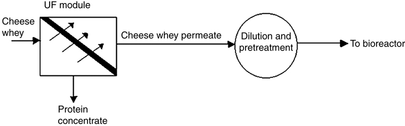
Figure 1.1 Pretreatment of Cheese Whey.
The cheese whey permeate, which is now free from all proteins, can be used as the raw material (substrate) for lactic acid synthesis (after preliminary treatments and dilution to proper lactose content of 9.0 g/L).
Xanthan gum is another commercially important product that can be manufactured economically starting from cheese whey permeate. Xanthan gum is a versatile polysaccharide that has found extensive applications as a stabilizing agent, emulsifying agent, thickening agent, and viscosity regulator in food and dairy industries, manufacture of paints and printing inks, in paper and textile industries. It is an excellent stabilizer for salad dressings and frozen and chilled dairy products. It is also used as an additive for enhanced oil recovery during mining and extraction of petroleum oils.
Cheese whey is fermented using a culture of Xanthomonas campestris. The process, unlike lactic acid synthesis, is aerobic in nature and, therefore, sterile air is to be injected into the bioreactor from the bottom. The use of a centrifugal fibrous bed bioreactor that accommodates the immobilized X. campestris has been recommended. However, this uses glucose solution as the starting material, which, as stated earlier, cannot be recommended for the commercial manufacture of Xanthan gum (being too expensive). Three-phase semifluidized bed biofilm reactors are attractive propositions for the manufacture of Xanthan gum from cheese whey. This is discussed subsequently in this chapter.
Molasses is another agricultural waste that has high potential for use as raw material for the commercial synthesis of lactic acid. It is the waste liquor discharged from cane sugar manufacturing industries. Sugar (or sucrose) is principally manufactured from sugar cane. Molasses is the mother liquor left behind after the crystallization of sugar from sugar cane juice. It still contains some dissolved sugar (dissolved sucrose) that cannot be further extracted economically on commercial scale. Molasses also is mostly discarded as waste liquor. At present, the only process in which it is used as a raw material is in the manufacture of ethanol (bioalcohol) by fermentation. The sucrose content of molasses is first hydrolyzed to glucose (and fructose) by the enzyme invertase (the process being called inversion of sucrose) and the glucose is subsequently converted to ethanol and carbon dioxide by the enzyme zymase.
Like cheese whey, molasses is also a very promising raw material for biochemical synthesis of lactic acid. Being a waste effluent, the cost of raw material in this case is also practically negligible. The sucrose content of molasses can be fermented to lactic acid using a microbial culture of Enterococcus faecalis. Molasses is to be diluted to a sucrose concentration of 70–150 g/L prior to fermentation. High sucrose concentration prevents microbial growth, since sucrose acts as an inhibitor. The scheme is
 (1.2)
(1.2)1.2. Process of Ultrafiltration and Equipment
UF, like reverse osmosis (RO) and other membrane-based processes, is also a chemical potential-based process. If we consider two chambers separated by a semipermeable membrane (UF membrane) as shown in Fig. 1.1, then the compartment on the left side of the membrane forms the feed compartment (compartment I) and the other, the permeate compartment (compartment II). Let a salt solution be pumped to the feed compartment and let pure solvent (say, water) be present in the permeate compartment. Since concentration of the solvent in the permeate compartment is higher than that in the feed compartment, the solvent will permeate through the membrane (the membrane used is essentially solvent permeable) from compartment II to compartment I, thereby diluting the feed solution. The transfer of solvent occurs from higher solvent concentration to lower solvent concentration. More precisely, the transfer occurs from higher chemical potential (μ2) to lower chemical potential (μ1). Here, μ2 is the chemical potential of the pure solvent which is higher than that of solvent in the salt solution (μ1). However, chemical potential is a function of temperature, pressure, and concentration. Mathematically,
 (1.3)
(1.3)As a result, if we increase the pressure on the feed side of the membrane (in other words, if we increase the pressure at which the feed solution is being pumped to the feed compartment), then the chemical potential of the solvent in the solution on the feed side (μ1) would increase. If the pumping pressure is gradually increased, the chemical potential (μ1) would continue to increase and at a particular stage, the value of μ1 would become equal to that of μ2. At this stage, the transfer of solvent across the membrane would cease (since μ1 = μ2). The pressure at which this occurs is called the osmotic pressure of the solution (π). In other words, osmotic pressure of a solution represents the pressure required to raise the chemical potential of the solvent in the solution to that of the pure solvent at any given temperature. Thus, when the pressure difference across the membrane (the transmembrane pressure drop, ∆P) becomes equal to the osmotic pressure difference (∆π), solvent transfer across the membrane ceases. Here,
 (1.4)
(1.4) (1.5)
(1.5)where P1 is the pressure on the feed side of the membrane (the pressure at which the salt solution is being pumped to the feed compartment) and P2 is that in the permeate compartment. In most cases, P2 = 1 atm. If P1 and thereby (∆P), is increased further, then μ1 would become larger than μ2 and the solvent will start permeating from the feed compartment (compartment I) to the permeate compartment (compartment II). This is what is called RO or UF. This occurs when and only when
 (1.6)
(1.6)or
 (1.7)
(1.7)Note that π1 and π2 represent osmotic pressure of the concentrated solution (discharged from compartment I) and that of the permeate solution, respectively. If the permeate solution is pure solvent, then π2 = 0.0. It may be noted that the transfer of solvent is occurring from compartment I (where its concentration is low and continues to decrease) to compartment II, where its concentration is high and continues to increase. In other words, the transfer occurs against the concentration gradient (from lower concentration to higher concentration). However, the law of thermodynamics (which is an universal law) has not been violated at all, since the transfer still occurs from a higher chemical potential to a lower chemical potential (μ1 > μ2).
The major difference between RO and UF is that RO membranes are too selective and permit essentially the solvent to permeate through (and they retain practically all the dissolved solutes whether of low molecular weight or high molecular weight), while UF membranes are of larger pore size and they retain only the high molecular weight solutes (low molecular weight solutes and the solvent permeate through the membrane).
It must be kept in mind that osmotic pressure of a solution is very much influenced by the temperature as well as the concentration and molecular weight of the dissolved solute. As the concentration of the dissolved solute in compartment I increases continuously due to discharge or separation of the solvent, the osmotic pressure of the solution (π1) also increases. To maintain the stability of the process, therefore, the operating transmembrane pressure drop (∆P) is selected from Eq. (1.6), by putting π1 = osmotic pressure of the final concentrate (final concentrated solution) discharged from compartment I.
Also, the higher the molecular weight of the dissolved solute, the lower will be the osmotic pressure of the solution. Since the final concentrate discharged from a UF unit shall be composed of high molecular solutes only (e.g., milk proteins), the osmotic pressure of this concentrate (π1) shall be quite low. Consequently, the operating transmembrane pressure drop (∆P) required shall also be low (of the order of 3–7 atm). The operating cost of UF units shall be thus much lower, as compared to RO units in which an operating transmembrane pressure difference of 30–40 atm is required to be maintained.
UF shall be thus an efficient as well as economical process for the separation of proteins from cheese whey. Since the proteins are of high molecular weight, the concentrate is of low osmotic pressure and consequently, the transmembrane pressure difference (operating pressure of membrane module) required is low, such as 3–5 atm. The membrane may be made of treated polyamide, polysulfone, or polyfuran. Thin film polymer composites are also popular.
The UF module employed may be spiral-wound (this employs sheet membranes) tubular, or hollow fiber type (Figs. 1.2–1.4). Spiral-wound UF modules (Fig. 1.2) employ spiral cartridges 10–20 cm in diameter and 0.5–1.0 m in length. They provide large membrane surface (300–900 m2/m3), but are relatively more complex to construct and are not readily amenable to cleaning. The feed solution flows axially (parallel to the membrane surface) from the feed end to the discharge end (concentrate end). A plastic netting is often inserted into the feed channel to induce turbulence and to minimize concentration polarization (discussed subsequently).
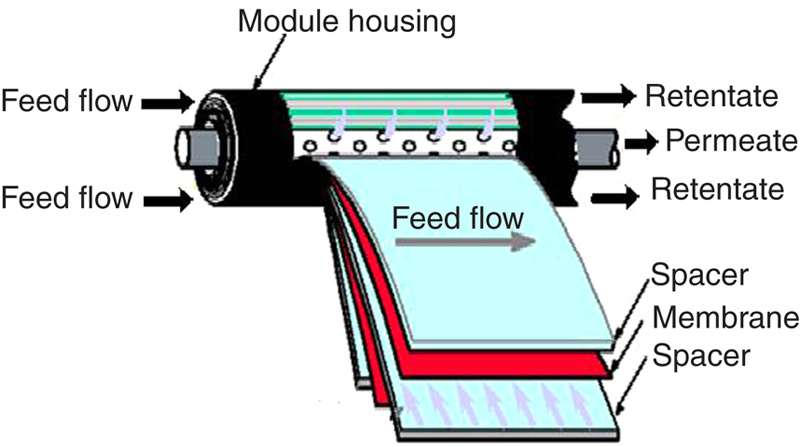
Figure 1.2 Schematic of Spiral-Wound Ultrafiltration Module.

Figure 1.3 Schematic of Tubular Ultrafiltration Module.

Figure 1.4 Schematic of Hollow Fiber Ultrafiltration Module.
The tubular module (Fig. 1.3) employs 20–100 perforated tubes, each 12.5–25.4 mm in diameter and the inside surface of each being coated with the membrane. The entire tube bundle is enclosed in a cylindrical shell (made of stainless steel or ceramic/polymer composites), thereby resembling a shell and tube heat exchanger. The feed solution is pumped through the tubes, the permeate being discharged from the shell. The concentrate (or retentate) leaves the other end of the module. Tubular modules provide relatively lower membrane area (150–300 m2/m3), but have good resistance to mechanical damage and are more amenable to cleaning.
Hollow fiber devices (Fig. 1.4) consist of a fiber bundle (2.0–4.0 million fibers are used, each of a diameter of 500–1000 μm) enclosed in a cylindrical shell. Each fiber is made of the membrane material. The feed solution flows through the fibers and the concentrate (or retentate) is collected from the other end of the module. The permeate collects in the shell and is discharged through the shell outlet nozzle. These devices provide very large membrane area per unit volume (9,000–10,000 m2/m3) and are extremely compact. But, they are more complex to construct and maintain, less amenable to mechanical cleaning. Problems due to concentration polarization are lowest in these devices.
As in the case with all separation processes involving selective transport, concentration polarization is a phenomenon (though undesirable) that inevitably occurs in UF, also. Due to build-up of retained solute at the membrane surface (membrane–liquid interface), a concentrated boundary layer, called the gel layer, is formed there. This gel layer offers additional resistance to the transport of solvent (and low molecular solutes) and tends to decrease the effective permeate rate. This is what is termed as concentration polarization. Turbulence promoters (plastic nettings in spiral-wound devices, static mixers) are often introduced into the flow field to minimize this effect. An alternate proposition is to use tubular membrane modules of diverging–converging design (Narayanan, 2011a). Each tube is of diverging–converging geometry (Fig. 1.5) with a minimum diameter (D1), maximum diameter (D2), and segment length (LS). The angle of convergence/divergence (θ) employed is only 5 degree (tan θ = 1/12). From simple geometry, it can be easily deduced that
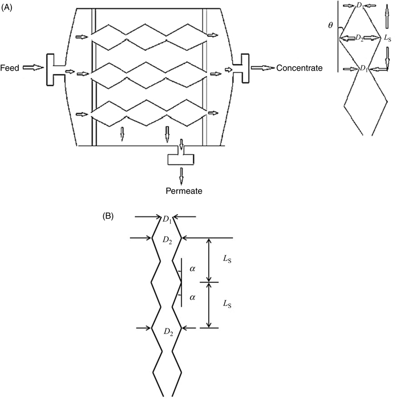
Figure 1.5 (A) Schematic of constricted tube ultrafiltration module. (B) Schematic of diverging–converging geometry (separate view).
 (1.8)
(1.8)The dimensions D1, D2, and LS are so chosen that tan θ is close to (1/12).
Such a module has been reported to minimize problems due to concentration polarization and membrane fouling (clogging) and consequently providing higher permeation rates and enhanced solute rejection (Narayanan, 2011a,b). The operating cost of the module is only marginally higher than that of a straight tube module of same membrane area per unit length, though there will be an increase in the fabrication cost and initial installation cost.
Fermentation of cheese whey permeate and molasses to synthesize lactic acid can be performed in fluidized bed, semifluidized bed, or inverse fluidized bed bioreactors or in downflow stationary fixed film (DSFF) bioreactors. The lactose concentration of the cheese whey permeate is to be adjusted to about 9.0 g/L in advance to promote adequate bacterial growth and activity. Similarly, the sucrose concentration of molasses must be adjusted to 70–150 g/L, prior to feeding to the bioreactor. Computer-aided design and operation of the previous bioreactors are discussed in detail in the next section.
1.3. Synthesis of Bioplastic From Food and Agricultural Wastes
The lactic acid synthesized is of polymer grade. It can be used as the starting material (monomer) for the manufacture of the bioplastic, polylaevo lactic acid (PLLA). The overall reaction may be represented as:
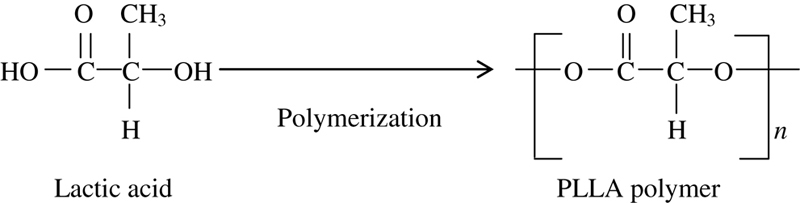 (1.9)
(1.9)
PLLA is one of the most promising environmentally friendly (green) plastics of the era, since it closely resembles polystyrene (PS) and polypropylene (PP) in most of its properties. In addition, it is also biodegradable by soil bacteria. The disposal of plastic waste shall not, therefore, cause any environmental concern. Waste PLLA can be composted in earthen trenches along with other biodegradable materials, such as plant and vegetable wastes and animal wastes. A comparison between the characteristics of PLLA and those of PS and PP is illustrated in Table 1.1.
Table 1.1
Comparison between PLLA bioplastic and synthetic plastics (PP, PS).
| S. No. | Property | PP | PS | PLLA Bioplastic |
| 1. | Density, kg/m3 | 905–940 | 960–985 | 1210–1400 |
| 2. | Melting point, ˚C | 171–186 | 220–230 | 170–180 |
| 3. | Tensile strength, MPa | 39–40 | 46–60 | 68–70 |
| 4. | Glass transition temperature, ˚C | −15.0 | 95–100 | 60–65 |
| 5. | Biodegradability | Nil | Nil | Good |

PLLA, Polylaevo lactic acid; PP, polypropylene; PS, polystyrene.
The PLLA bioplastic can thus substitute popular synthetic plastics, such as PS and PP in all industrial/domestic applications. It is, in fact, superior to synthetic plastics due to its biodegradable nature and thus is truly a green plastic. However, the present market price of PLLA bioplastic is much higher (almost 8–10 times higher) than commercial synthetic plastics, such as PS and PP. This is due to the high cost of the raw material used for the monomer (lactic acid) synthesis. At present, lactic acid synthesis is being practiced starting from lactose, glucose, or sucrose, which are very expensive raw materials and cannot be recommended for commercial manufacture of lactic acid.
Once, as stated earlier, lactic could be synthesized economically on a commercial scale starting from waste effluents, such as cheese whey or molasses, then the manufacturing cost of PLLA shall decrease significantly and its market price shall become comparable with that of popular synthetic plastics, such as PS or PP.
Polymerization of lactic acid to PLLA biopolymer can be accomplished without much difficulty through well-established processing techniques and equipment (Shreve, 1977; Steinbüchel, 2001).
Lactic acid is separated from the fermentation broth by precipitation as calcium acetate, which is subsequently hydrolyzed to lactic acid using dilute sulfuric acid. The precipitated calcium sulfate is separated by filtration and the recovered lactic acid is made to dimerize (at ordinary temperature and pressure) to form a solid, cyclic dimer. The formation of this cyclic dimer is relatively fast and occurs without the aid of high temperature or high pressure. The dimer is then melted and subjected to ring-opening polymerization in an autoclave. This process is exactly analogous to polymerization of caprolactam (also a ring compound) to polycaprolactam or Nylon 6 (Shreve, 1977). Nylon 6 is the first man-made fiber manufactured in the world (by Du Pont, USA). The same type of polymerization autoclave and the similar operating conditions (temperature = 200°C, pressure = 1.5 atm) could be employed in the case of PLLA production as well. Since the process of Nylon 6 synthesis is very well-established, the polymerization unit for PLLA synthesis could be designed and installed with confidence. As in the case of Nylon 6, the molten PLLA is extruded out from the polymerization kettle, then cooled in a blast of nitrogen gas and also under water to form long, endless polymer ribbons, which are cut into chips and stored. A schematic of the process is shown in Fig. 1.6A–B.
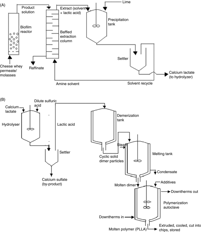
Figure 1.6 (A) and (B) Condensed Flowsheet of PLLA bioplastic synthesis.
2. Kinetics of Bioconversion
The bioreactors under consideration are biofilm reactors and they are heterogenous systems. The reaction mixture is composed of two phases, such as the solid phase (particle–biofilm aggregates) and the liquid phase (feed solution/substrate solution). In the case of heterogenous systems like this, it is necessary to define the intrinsic rate of bioconversion, (−rS)(int), as well as the global rate of bioconversion, (−rS), separately. The kinetic equations developed in the laboratory predict the intrinsic rate of bioconversion, which is the rate of bioconversion or biochemical reaction occurring in the biofilm. The global rate of bioconversion (which is the actual rate of bioconversion attained in the bioreactor) shall be lower than this. This is because in heterogenous bioreactors, an additional resistance comes into play, which is the resistance to substrate transfer into the biofilm. The substrate (in the present case, sucrose or lactose) has to first diffuse into the biofilm and thereafter, the reaction (bioconversion) occurs. This additional resistance to the transport of substrate into the biofilm is accounted for by the parameter called the effectiveness factor (η). In other words, the global rate shall be equal to the product of the intrinsic rate and the effectiveness factor. Thus,
 (1.10)
Computation of effectiveness factor (η) is discussed subsequently in this chapter. The value of η can be as high as 0.8–0.9 and as low as 0.45–0.5. Due to this additional resistance, the global rate does get lowered. However, due to the significantly high biomass concentration in the biofilm (xf), the rate of bioconversion in biofilm reactors shall be still much higher than that attained in a suspended-growth stirred tank reactor.
2.1. Principles of Kinetic Analysis
All the kinetic studies reported in literature are those that have been performed in laboratory shake flasks or conical flasks, in which suspended growth of microbes occur. For example, Anjana and Kumar (2008) have studied kinetics of fermentation of molasses to lactic acid (bioconversion of sucrose content of molasses to lactic acid) using a culture of E. faecalis RKY1. They observed that the process follows Monod-type kinetic equations. They report that though substrate inhibition to microbial growth is relatively insignificant, product inhibition to microbial activity does exist and cannot be neglected. However, as stated previously, in biofilm reactors under consideration [stirred tank bioreactors are restricted to small capacities and consequently, for commercial synthesis of lactic acid at large capacities, we have to employ fluidized bed, semifluidized bed, or inverse fluidized bed biofilm reactors or downflow stationary fixed film (DSFF) bioreactors], attached growth of microbes occur. These bioreactors either employ support particles made of silica, polymer composites, or activated carbon, each particle being surrounded by a thin film of microbial solution (biofilm) or vertical channels, the inner surface of each being coated with a thin film of microbial solution. Microbial growth does occur in the biofilm and the thickness of the film (δ) tends to increase. However, when the biofilm thickness increases beyond a certain value, it gets detached from the particle surface (the phenomenon termed as sloughing) and is immediately replenished by a fresh film. Also, the dead or decayed cells fall out from the biofilm and are almost instantaneously replaced by new living cells. Due to these, both the thickness of the biofilm (δ) as well as the biomass concentration in the biofilm (xf) remain more or less constant throughout the entire operation of the bioreactor. This is one of the exclusive characteristics of biofilm reactors.
Further, neither the substrate (sucrose or lactose) nor the product (lactic acid) accumulates in the biofilm and as a consequence, neither the substrate concentration nor the product concentration in the biofilm shall be of large magnitude at any instant. This brings down (in many cases, eliminates) the chances of occurrence of substrate inhibition or product inhibition to microbial growth and activity.
2.2. Development of Kinetic Equations
The kinetic equation proposed by Anjana and Kumar (2008) for suspended growth of microbes and substrate utilization gets modified to the following form when applied to attached growth (the product inhibition to microbial growth is neglected and the biomass concentration in the biofilm is assumed constant and equal to xf):
 (1.11)
 (1.12)
where (−rS) = intrinsic rate of substrate consumption/conversion, g/(L·s); μm, KS = kinetic constants; μm = maximum specific growth rate of microbes, h–1; KS = saturation constant, g/L; Y = overall yield coefficient for cell mass production, g/g; CS = substrate (sucrose) concentration in liquid bulk, g/L; xf = biomass (cell mass) concentration in biofilm, g/L; f = fractional volume of biofilm in particle–biofilm aggregate, m3/m3; ɛ = total voidage (or void fraction) of the bed, ɛf = in case of fluidized bed, ɛp = in case of packed bed or static bed); ɛL = fractional liquid holdup in the bed.
Assuming that all the voids of the bed are completely filled with the liquid (which is true in the case of most industrial fluidized bed bioreactors/packed bed bioreactors), ɛL = ɛ. For the same reason, we may very well assume,
 (1.13)
 (1.13a)
The parameters (f, ɛ, ɛL) have been additionally incorporated to maintain dimensional consistency. To note that xf stands for mass of microbial cells per unit volume of biofilm and therefore,
 (1.14)
Eq. (1.12) may be rewritten in a more compact form as
 (1.15)
where
 (1.16)
If dP is the diameter of the support particle (silica granule, polymer bead) and δ is the thickness of the biofilm (which, as stated earlier, remains more or less constant throughout the operation of the bioreactor), then the average size (diameter) of the particle–biofilm aggregate (dPm) is
 (1.17)
Accordingly,
 (1.18)
It may be noted that based on the above definition of f, the density of the particle–biofilm aggregate (ρSm) is
 (1.19)
where ρS = density of support particle; ρm = density of microbial solution.
The reported values of kinetic constants (Anjana and Kumar, 2008) are
 (1.20)
The kinetic equation [Eq. (1.11)] has been experimentally verified by Das and Narayanan (2016) as well. Based on their kinetic studies in the laboratory, Schepers et al. (2002) have reported that a kinetic equation of the type shown in Eq. (1.11) could be used for the fermentation of cheese whey permeate also (for the bioconversion of lactose content of cheese whey permeate to lactic acid) using a culture of L. helveticus. The magnitudes of kinetic constants shall be, however, different as given in Eq. (1.21):
 (1.21)
Once the kinetics of bioconversion is known, we can proceed to the design of bioreactors.
In the case of Xanthan gum synthesis from cheese whey, the process reportedly follows Contois-type kinetic equation (Zabot et al., 2011). As stated earlier, Xanthan gum synthesis is an aerobic process and we have to employ a three-phase biofilm reactor for the same. Accordingly the kinetic equation takes the following form:
 (1.22)
where
 (1.23)
 (1.24)
To note that ɛf is the total voidage of the fluidized bed (for the packed bed, this is to be replaced by ɛP) and ɛfL is the fractional liquid holdup in the bed (it is to be replaced by ɛPL in the case of packed bed). For a three-phase biofilm reactor,
 (1.25)
 (1.26)
where εPg and εfg are the fractional gas holdup in the packed bed and that in fluidized bed, respectively.
Readers must also take note of the fact the expression for μm(app) given in Eq. (1.23) (for three-phase biofilm reactor) is different from that given in Eq. (1.74) (for two-phase biofilm reactor). The major difference is that we may substitute ɛ = ɛf = ɛfL and ɛL = ɛfL in Eq. (1.16) for two-phase (liquid–solid) systems, but ɛ = ɛf and ɛL = ɛfL for three-phase systems (ɛ is not equal to ɛfL, but is larger than ɛfL).
Typical experimental values of kinetic constants reported by Zabot et al. (2011) are
 (1.27)