RepRap for Science—How to Use, Design, and Troubleshoot the Self-Replicating 3-D Printer
Abstract
The self-replicating rapid prototyper, or RepRap, is a low-cost open-source 3-D printer capable of fabricating components of scientific equipment with 100-μm resolution in a rapidly expanding list of materials. The RepRap both upgrades and literally maintains itself as it is capable of printing more than half of its own components in thermoplastics such as polylactic acid and acrylonitrile butadiene styrene along with hundreds of predesigned open-source scientific components. In this chapter, the design, use and troubleshooting of the RepRap technology is discussed in the context of creating high-performance customized scientific instruments. The bill of materials and detailed assembly instructions are provided for the MOST variant of the Prusa Mendel RepRap, which can be built by two people in a day for under $600. As the investment in a RepRap is capable of repaying itself after a few hours of printing even common scientific hardware, it is likely to become an indispensable resource for most laboratories as more sophisticated and customized open-source scientific tools are developed.
Keywords
3-D printing; Additive layer manufacturing; Customization; Fused filament fabrication; Open-source 3-D printer; Open-source hardware; RepRap; Rapid prototyping; Scientific equipment; Scientific instruments
5.1 Introduction to REPRAPS
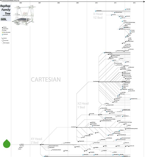
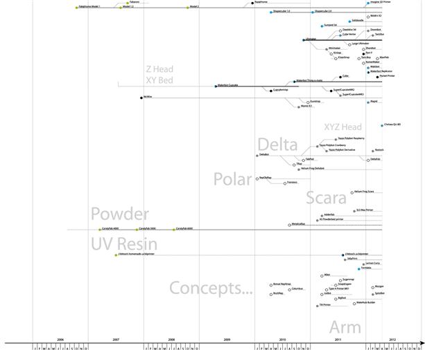
Although the term 3-D printing only goes back to 1995, the concept of 3-D printing or, as it is known in the technological literature, “additive manufacturing” of AM has been around for a while used for rapid prototyping since the late 1980s. The more recent technical explosion in innovation for 3-D printing has been substantial, fueling rapid growth in commercial rapid prototyping for a huge swath of industries [1–5]. There has been a considerable amount of hype built up around 3-D printing at this point and even speculation by the Economist that these technical advances could result in a “third industrial revolution” governed by mass-customization and digital manufacturing following traditional business paradigms [6]. In the Economist special issue, however, lost among all the fascinating stories of new companies and breathless explanations of the technologies is the fact that open-source 3-D printing is really what has cut the cost of rapid prototyping so low that it is now accessible to basically everyone. The recent development of open-source 3-D printers makes the scaling of mass-distributed additive manufacturing of high-value objects technically feasible for everyone [7–15]. Yet perhaps the first group to benefit the most financially is practicing experimental scientists [16]. These self-replicating rapid prototypers, or RepRaps were developed by Dr Adrian Bowyer, a professor in mechanical engineering at the University of Bath in 2005. Bowyer has a particularly clear view1 of what having a general-purpose self-replicating manufacturing machine means for humanity and how the project was able to literally evolve under the open-source paradigm [17,18]. This is why the major variants of the RepRap are all named after biologists Darwin, Mendel, Huxley, and Wallace. The RepRap evolutionary family tree [19] is shown in Figure 5.1.
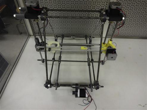
The MOST RepRap this chapter discusses in detail is a Mendel Prusa variant as shown in Figure 5.2.
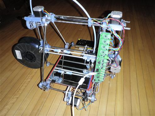
FIGURE 5.2 A new variant of the Prusa Mendel RepRap and open-source 3-D printer capable of fabricating about half of its own parts. In the picture, all the translucent blue parts were printed on an identical mechatronic machine. The variants were engineered by G. Anzalone and this particular printer was built by J. Irwin. At this point, the printer shown is a great-great-great-great-great granddaughter of one of Bowyer’s original RepRaps.
The RepRap project has created 3-D printing machines that can manufacture approximately half of their own parts (57% self-replicating potential excluding fasteners, bolts and nuts) from sequential fused deposition of a range of polymers and common hardware [7,20,21]. The RepRap is a mechatronic device made up of a combination of printed mechanical components, stepper motors for 3-D motion and extrusion, and a hot-end for melting and depositing sequential layers of polymers, all of which is controlled by an open-source microcontroller such as the Arduino discussed in the last chapter [7,22,23]. The extruder intakes a filament of the working material (polylactic acid (PLA), acrylonitrile butadiene styrene (ABS), and high-density polyethylene among materials [24]), melts it using resistive heating, and extrudes it through a nozzle. The printer uses a three-coordinate system, where each axis involves a stepper motor that makes the axis move until reaching a limit switch for homing. The printing process is a sequential layer deposition where the extruder nozzle deposits a 2-D layer of the working material, then the z (vertical)-axis will raise, and the extruder will deposit another layer on top of the first building a 3-D object in 2-D layers. RepRaps have been proposed and demonstrated to be useful for developing engineering prototypes [20], education [25], creating electronic sensors [26,27], cocreative product realization [28], personal manufacturing [29], modular robotics [30], wire embedding [31], tissue engineering [32] and appropriate technology manufacturing for sustainable development [11]. Here, we are, of course, most interested in the RepRap as an extremely powerful and low-cost tool for helping to fabricate customized scientific equipment [16,26]. In the sections that follow, we will discuss how to build a RepRap, and use it to make open-source scientific hardware.
5.2 Building a REPRAP
The version of the RepRap detailed in this chapter is a variant of the Prusa Mendel reengineered primarily by Jerry Anzalone at Michigan Tech. We have built several of them at Tech, including several pilot workshops where dozens of teachers (college and high school) were trained in how to build and debug them. The goal of this particular version is a low-cost RepRap with high print speeds, good quality and that it is extremely easy to build and debug. For this purpose, the MOST RepRap has a new y-axis stage that gives you both a larger effective print envelope and the ability to increase print speed. If you follow the instructions below, your RepRap will be ready in <24 h of work (two people can build it comfortably in a working 8 h day, particularly if they are experienced). That said, just like all RepRaps, these designs are constantly evolving and the most up-to-date build instructions can be found in the Appropedia wiki.2 My research group maintains a small community centered on an Appropedia page to assist in troubleshooting and share user experiences.3 In addition, there is a much larger RepRap Forum4 and community at the main RepRap wiki.5
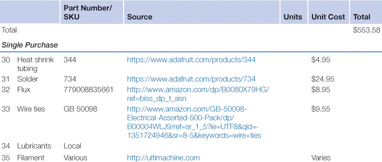
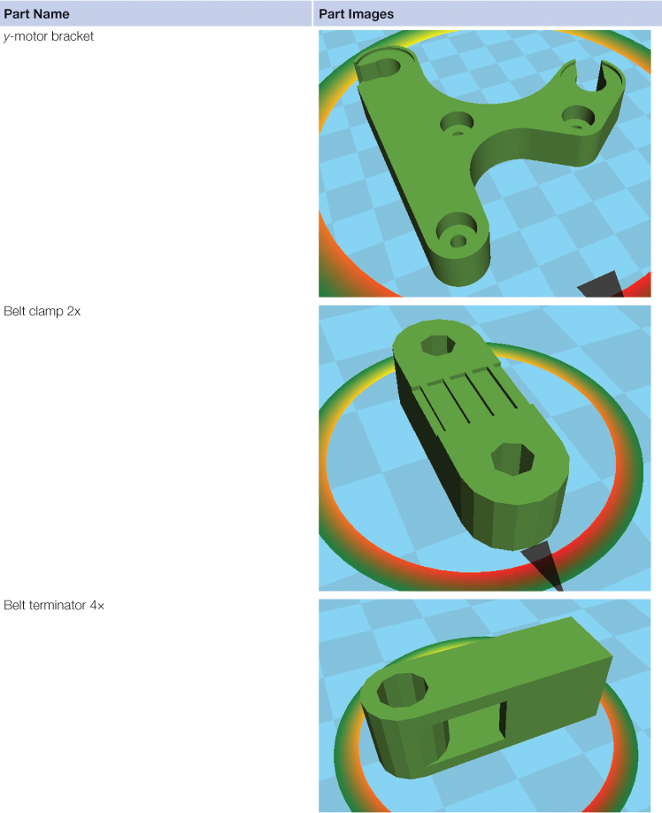
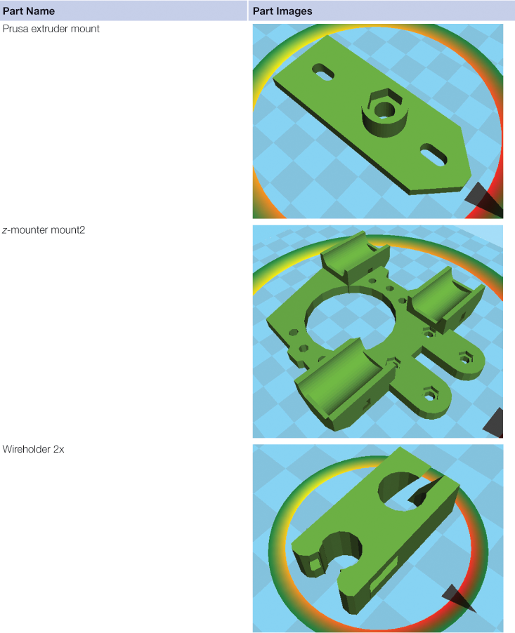
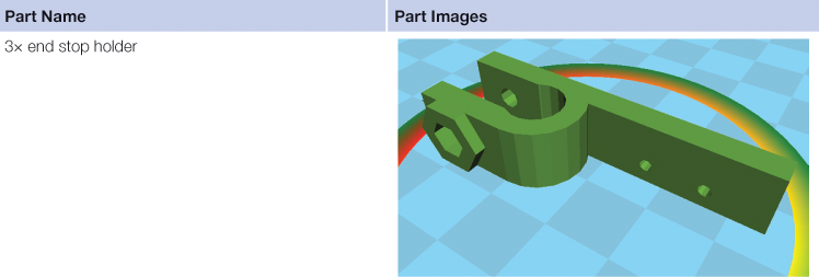
Before assembling, first ensure you have all the parts necessary in the bill of materials (BOM) as shown in Table 5.1, the printed parts in Table 5.2, and the necessary tools are listed below. First download the zip file of the MOST STereoLithography (STLs).6 Convince someone you know7 with a 3-D printer to print all of the STLs shown in Table 5.2 with PLA unless otherwise indicated by ABS following the file name (you can print them all in ABS, but it is unnecessary and in general, PLA is better to work with because of substantially less fumes). Printing all the parts on a standard RepRap printer with normal settings should take <24 h of print time. The printed parts for the MOST RepRap in the link provided are plated and color coded for easy identification and assembly. In addition, if you simply print all the plates you can be sure your part count is right in place of Table 5.2.


The following tools will make the building of your RepRap fast and easy although they are not all absolutely necessary. For example, you do not absolutely need work gloves, but then you need to be more careful handling the edges of sharp components. Similarly, there are other alternative tools you could use to clean out holes of printed components, but the sizes lists will make it a faster task.
1. Wrenches: (2) 13 mm, 7 mm, and 5.5 mm.
2. Hex key (Allen key) set: 5, 4, 3, 2.5, 2, and 1.5 mm.
5. Utility knife blades—used as scrapers to clean the sharp edges of printed parts.
6. Drill bit size 5/16″ and #9 (0.196″) (to clean out holes; ideally 8, 5 and 3 mm).
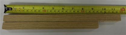
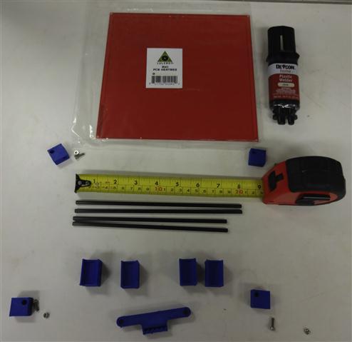
7. Wood jigs (290 and 234 mm) shown in Figure 5.3.
8. Gloves—to prevent cutting fingers on threaded rod and sharp edges of printed parts.
9. White lithium grease (to lubricate bearings).
11. File or thread-chaser to clean up cut threaded rods.
12. Zip ties for wire management.
13. Small vice grips to hold drill bits for reaming (or you can use 3-D printable handles)8
14. Pencil sharpener—if you do not have one, you can use a knife or utility knife blades.
5.2.1 Bill of materials by component
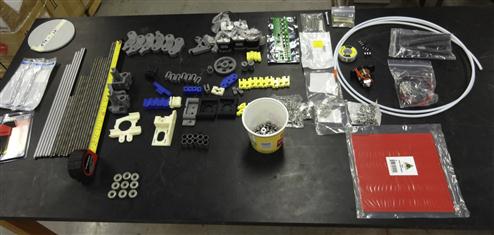
In order to assist in fast assembly, the BOM from Table 5.1 is broken down here into main components. The complete BOM is shown in Figure 5.4. I recommend purchasing the entire BOM and then breaking them up and ordering in the follow subcategories, which we will then step through building.
5.2.2 Assembly instructions
There are some exceptionally detailed and well-written descriptions about how to build a standard Prusa RepRap. For the simplified version of the RepRap presented here, rather than tell you exactly where to place each nut and bolt, figures are provided that should make it apparent from the list of parts for that particular component. We have tried these build instructions out with several faculty and student builds, which were successful with only minor supervision from experienced RepRap builders. You should be able to build the RepRap on your own, but it is more easily accomplished with a team of two. Ideally, you would have access to an experienced RepRap user to help you through any unclear parts. Even if there is no one in your company or institution available, the RepRap Internet Relay Chat (IRC) channel is always available to let the open-source community answer quick questions.9
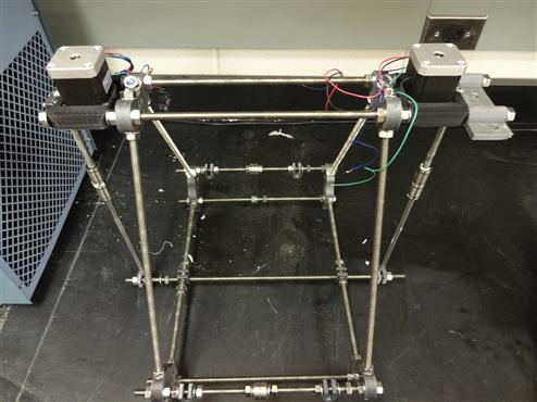
5.2.3 The frame
There is an equilateral triangle on each side of the frame of the MOST RepRap as seen in Figure 5.5. Initial assembly will be very loose. Do not tighten the nuts or be overly concerned about their placement during first assembly steps; everything will be tightened up and properly placed in future steps.
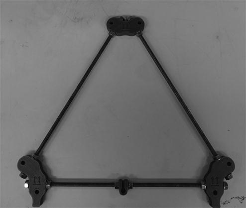
Follow the image in Figure 5.5 and build two triangles each with two footed frame vertices, one unfooted frame vertex, one rod clamp on the threaded rod connecting the two footed vertices, 14 M8 nuts, 14 M8 washers and three 370 mm M8 threaded rods.10 Using the 290-mm-long jig, space each vertex from its neighbors and tighten the nuts so that a rigid triangle is formed. The jig should be placed such that it is against the printed vertices near the washers, but not on the washers. To make sure the holes line up, you can lay the triangles on top of each other and insert six M8 bolts through each hole in the vertices. The bolts should go through holes in both vertices easily, adjust the frame a little if necessary.
5.2.3.1 Building the bulk of the frame
When you build this, make sure you do not tighten down any of the bolts—it should be super loose to start. The additional parts needed to fabricate the rest of the frame with your two triangles are three 440 mm M8 threaded rods (the long ones), 16 M8 washers and 16 M8 nuts.
Put the frame together with the long rods as shown in Figure 5.6. You are already done with the frame! Nice work.
5.2.4 The y-axis (back and forth)
The y-axis consists of two sides each consisting of a pair of threaded rods with only slight differences in what is placed on these rods. The assembly of the top rods is identical, whereas the lower rods are assembled slightly differently. Note the distinction between motor end and idler end—the motor end has additional nuts and washers on the lower rod.
5.2.4.1 Building the y-axis upper rods
Sometimes the rods are hard to thread. If you are having difficulty threading, chase the threads with an M8× 1.25 die or jam a pair of nuts on one end of the threaded rod and use wrenches to increase the amount of torque applied.
You will need two sets of the following parts needed for each side:
Starting from the left order of assembly (assembly is symmetric about the 608 bearings): washer, nut, nut, washer, rod clamp, washer, nut, nut, washer, washer, 608 bearing, 608 bearing, washer, washer, nut, nut, washer, rod clamp, washer, nut, nut, and washer. The proper order is shown in Figure 5.7.
Build two identical copies of Figure 5.7. Mount them through the upper holes of the bottom, footed vertices. Add a washer and nut to each end, but continue to leave the assembly loose to accommodate placement of parts during later steps.
5.2.4.2 Building the bottom rods
The parts you need for motor end are the following:
Parts needed for idler end are the following:
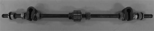
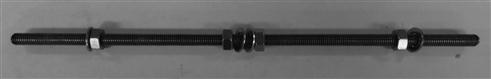
To assemble on the motor end, bottom rod (motor side) follows Figure 5.8: washer, nut, nut, washer, washer, nut, nut, and washer.
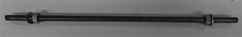
Then follow Figure 5.9 for the idler end bottom rod (idler side): washer, nut, nut, and washer. Mount rods to the frame with a washer and a nut on each side are shown in Figure 5.10. It does not matter which side at this point of the build. Again, remember to leave the assembly loose at this point—tightening will take place later.
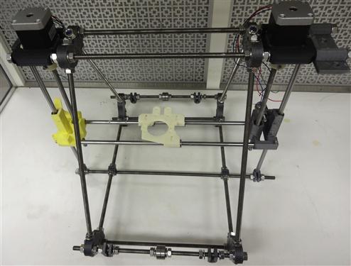
5.2.5 The z-axis (up and down)
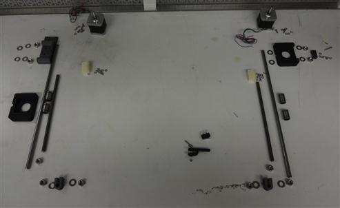
First, obtain all the z-axis components shown in Figure 5.11.
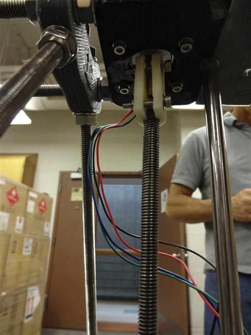
To assemble the z-motor mounts, face the y motor mount toward yourself and then on the right put on z-motor mount with a washer, washer, and nut. Use the smaller jig to get the distance between the two triangles more or less right. Then put on the second z-motor mount on the left with washer, washer, and nut. Mount the motors to the motor mount with M3 screws as shown in Figure 5.12. Next, put a nut, washer, rod clamp, washer, and nut on each side of the bottom threaded rod. Then put the vertical smooth rod through the bottom-rod clamp and use a level to adjust the bottom-rod clamps to the correct position. Lubricate the LM8UU bearings with white lithium grease. Attach the smooth rod from bottom to top on both sides with two bearings on each smooth rod as seen in Figure 5.12.
5.2.6 The x-axis (left–right)
First, obtain all the x-axis components shown in Figure 5.13. Then, assuming that the printed parts you are working with are not perfect, clean up motor end of the x-axis with a knife or needle-nose pliers as seen in the yellow parts of Figure 5.14, which show before (right) and after cleaning (left). You also need to use a knife to dig out a hole in the big nut trap, but using a drill bit is usually easier. Load M3 nuts into the x-axis and use a threaded rod to push through to the bottom and then thread the screw for both of the deep nut traps as shown in Figure 5.15.
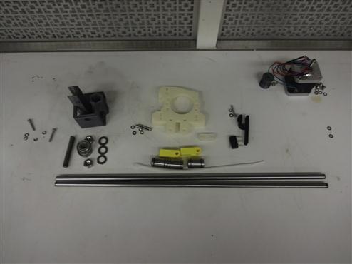
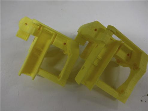
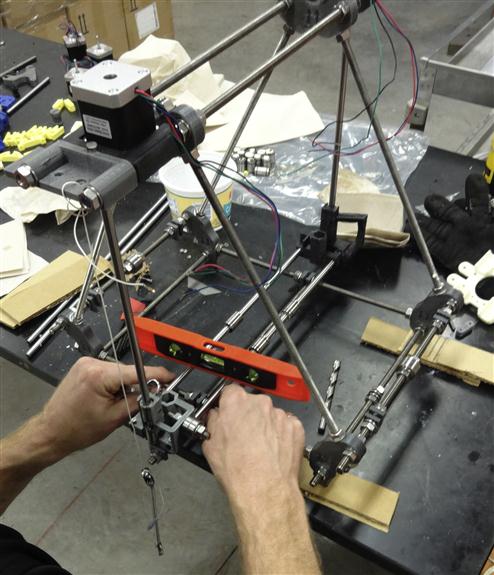
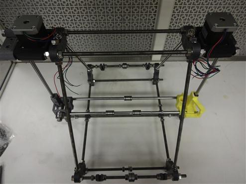
FIGURE 5.14 Motor end of the x-axis before (right) and after (left) cleaning with a knife or needle-nose pliers.
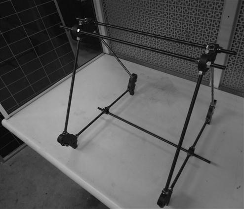
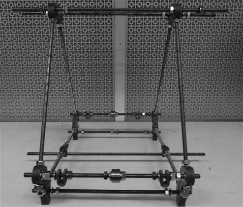
Next construct the idler as shown in Figure 5.16 in the following order: nut, washer, plastic, washer 2 bears, washer, and nut. After the idler is complete, load bearings on the motor and idler sides (two on each of the z-axis) and mount on vertical smooth rods as shown in Figure 5.17. Slide the two smooth rods through both of the plastic x-axis sides. Mount the x-stage with three bearings on the two smooth x-rods (two bearings on the motor side and one on the other). Then put M3 × 20s all the way through the idler side with washers and bolts. For details, see Figure 5.17. Your x-axis should be complete so now make sure it is level. You can also use a plumb bob to ensure that the vertical smooth rods are directly vertical as shown in Figure 5.18. Repeat this step on the other side. The stage should slide up and down effortlessly, when it does tighten it all down. You should now have a completed frame with x, y and z, all set up as shown in Figure 5.19.

The last step to complete the main portion of the mechanical assembly is to attach the x-stage to z-stage. Take the couplings that couple the shaft to the motor and clean them out. These couplings take a pair of M3 × 20 screws and M3 nut and M3 washers and they fit into the nut traps on the coupler. Mount the coupler and the z-axis threaded rod (210 mm M8 threaded rod) as seen in Figure 5.20. Please note that the couplers are printed in ABS for flexibility. The coupling ends may need to be reamed out with a drill bit, however, ensure that there is a snug fit after reaming and prior to tightening the screws.11 Pull the x-axis up—use a wire to temporarily tie it to the top frame and put two M8 nuts on the z-axis threaded rod on both sides.
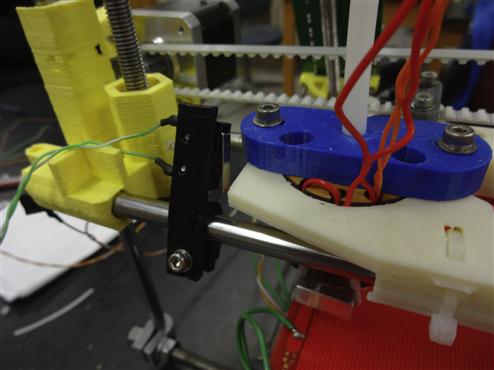
Release the x-axis back onto the nuts as shown in Figure 5.21. Use three small zip ties to tie the x-axis stage to the three bearings. Next, mount the pulley to the x-axis stepper motor with M3 trap nuts and M3 × 10 grub screws and mount the motor with three M3 × 10 screws as shown in Figure 5.22. Cut 875 mm of belt and attach the belt terminator as seen in Figure 5.23. Pull on the belt carefully and the teeth will mate. This may take a couple tries until you get it to lock in tightly. Run the belt through the pulley on the motor side and then the idler and put on the second belt terminator using the same method shown in Figure 5.23. Then use a zip tie to tie both terminators together.
The terminators should be on the top as shown in Figure 5.24. Use a belt clamp and two M3 × 20 nuts, washers and bolts to attach the belt to the x-axis stage. While attaching, make sure that the belt terminators and the stage are on opposite sides of the printer (as shown in Figure 5.24).
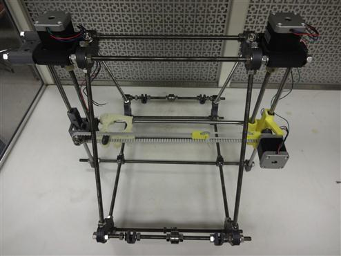
5.2.7 Attaching the y-stage
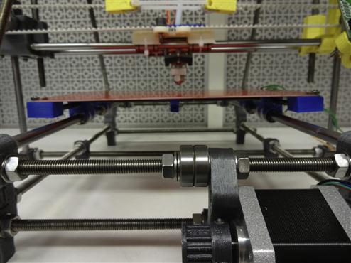
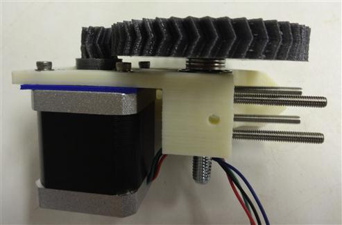
Slide out the two smooth rods for the bottom y-stage and put on two LMU bearings on each side. Make sure the smooth rods are on top. Snap on the y-motor mount in between the double sets of washers on the base (Figure 5.25). Mount the pulley with two M3 nuts and M3 grub screws to the last stepper motor. Mount the motor to the y-motor mount using three M3 washers and screws. (Note: be careful about the orientation of the pulley on the motor.)
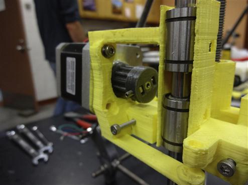
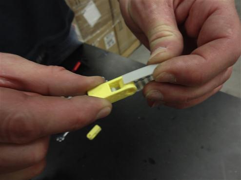
Assemble the BOM for the super-slim y-stage (shown in Figure 5.26):
Two of each carbon fiber rods12: 200 and 185 mm.
Four corners, four saddles and one spacer (or print plate01.stl).
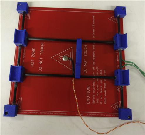
Next put them all together as shown in Figure 5.27, which is showing your completed goal for the stage. Start by printing or procuring the four corners, four saddles and one spacer (or print plate01.stl). Then measure carbon-fiber rods. You can cut the fiber rods with a utility knife (score the rod to length, then roll the rod under the blade while applying pressure). You can also cut it with a hacksaw, but be careful to drag it back slowly as carbon fiber will tear. Next, put an M3 nut and M3 × 10 mm screw into each corner. Use the heated build platform circuit board to space the corners correctly. Then, push two saddles onto a rod and put one of the corners onto a corner of the board with a nut. Make sure to put the trace side up as the deep holes on the corners must be facing up. Next, push one end of the rod with the two saddles on it into the corner on the board. Push another corner onto the opposite end and attach it to the board. Repeat this identical process on the other side. Put the entire stage together. Make sure everything fits and is in the right direction. Make sure that the holes for the saddles are facing inward. If it does, remove one corner piece from the board and carefully apply a little epoxy to the ends of the rod, push the corner pieces back on and reattach the corner piece to the circuit board with a nut. Rotate the rod and move fore-aft to get the epoxy smeared around. Repeat the process on the other side. Make sure to put the saddles on first before you epoxy everything!
To get to this point should take you <8 h even assuming you were taking your time and stopping for food and restroom breaks. At this point, you can either push forward on the extruder or go do something else while the epoxy dries (like sleep or if you are married, take your spouse out to dinner—trust me on this. 3-D printing is addictive particularly when you first start and it is always a good idea to keep your spouse happy.).
After the epoxy has set, move the saddles so that they are relatively equally spaced one-third of the length of the rod. Put the other two rods through the spacer. Loosen the nuts on the corner pieces, so the parallel rods can be moved slightly. Then, push the cross-rods into the holes on the saddles and tighten the nuts so that the whole assembly is relatively fixed to the board. Finalize spacing of the saddles pushing the spacer from one side to the other. When happy with their position, apply a small dab of epoxy to each saddle/parallel rod to affix the saddle to the parallel rods. Let the epoxy set. Loosen the nuts, remove the cross-rod ends from the saddles and apply epoxy to the ends of the cross-rods. Reinsert the cross-rods into the saddles and rotate them and push them side to side to smear the epoxy. Tighten the nuts, so the assembly is rigid and fixed. Again, you can skip ahead and come back to finish when it is dry or take a short break.
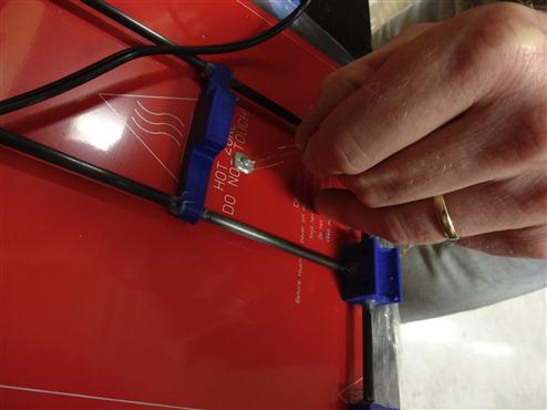
Turn your attention to the heated build platform. Use silver epoxy to mount a thermistor to the heating stage as shown in Figure 5.27. Space the y-axis guide rods so that the saddles fit snugly on the bearings, tighten everything up, and affix the bearings to the saddles with small zip ties. Then, align the y-axis drive belt with the dog and push the belt into the dog. Move the carriage fore and aft to assure motor and idler are aligned properly and tighten everything up. Now make sure you have everything installed correctly. Ensure that the y-axis is plumb with the x-axis. You can use calipers or measuring tape to ensure equidistance on each side between the x- and y-slide rods. (Please note: Never skimp on the alignment as it will become incredibly important when we get to the stage of actually printing.)
You can make the following optional design change to make leveling the bed easy in the future: if you want you can use four M3 × 20 mm screws instead of four M3 × 10 mm screws for attaching the bed. This will require eight more M3 nuts (12 total), but allows for easy bed leveling in the future. To do this, just put an M3 nut in the nut trap on the corner pieces and screw the M3 × 20 until it is tight. Then screw another M3 nut down the M3 × 20 and put the heated bed on top and secure with another M3 nut. Repeat these steps for each corner piece. You may want to do the initial setup to make sure the layup is proper and epoxy is set before changing.
Additional components you will need to complete the y-axis are the following:
Next, it is time to mount the y-axis as shown in Figure 5.28. Orient y-motors facing you, push the nuts to the left side of the frame and tighten jam them up. Pull the excess y-axis guide rods toward the side with the motor and tighten them down. Push two wire ties through each saddle. You will find it easier to pull them through using needle-nose pliers. Mount the heated bed to your printer with the wires facing the Melzi and line up all your bearings. If the z-axis is getting in the way, move the z-axis nuts up. Next, tighten down the wire ties over the bearings. Now, slide y-axis back and forth—while trying to minimize friction—and then tighten the M8 nuts in place. The y-axis should slide back and forth with very little drag—adjust the y-rods as needed and slide it back and forth until it slides smoothly.
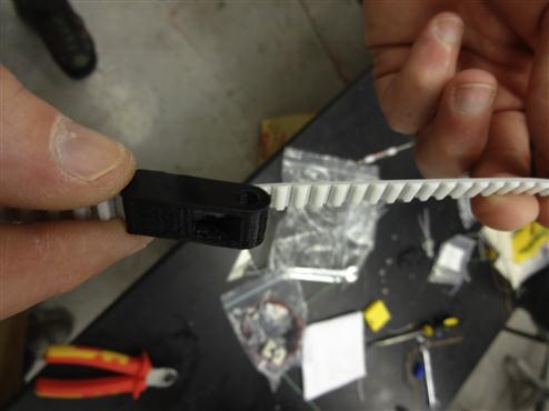
Now you are ready to add the belts. Cut the y-belt to 125 mm in length. Trim the ends of the belt, so that it terminates with a tooth. Put belt terminators at both ends of the belt as shown in Figure 5.29 following the same procedure as the belt terminators described above. Loop the belt around the y-motor shaft and idler shaft and then tie into place with a zip tie so that it is somewhat loose.
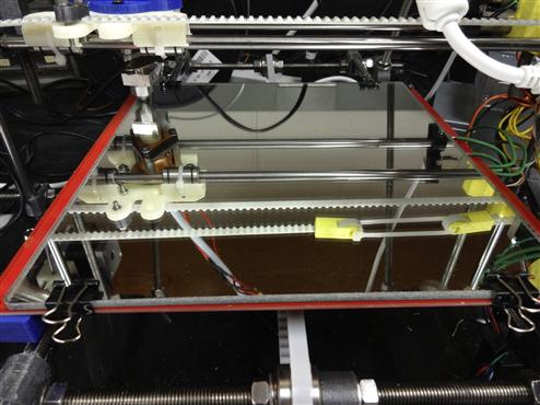
Now, tilt the printer on its side and push the y-stage all the way to the limit switch and then pull the two belt terminators to the other side as shown in Figure 5.30. Then slip the teeth of the belt into the dog on the stage. Move the M8 nuts on the main rods to assure that the y-motor and the idler until the belt does not walk when you move the y-axis back and forth. When everything is aligned, tighten the bolts down and then pull on the zip tie to make the belt tight enough to “twang” like a guitar. Put the glass or mirror (only because it looks more interesting) precut to size on top of your bed and hold in place with four small binder clips as shown in Figure 5.31.

5.2.8 The extruder
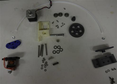
Gather the BOM as shown in Figure 5.32 for the extruder:
One Bowden sheath 2 ft long (8 inch OD, eigth by a quarter ID, PTFE tubing).
One-inch threaded rod idler shaft.
Use a pencil sharpener to trim down both sides of the Bowden sheath as shown in Figure 5.33. If you do not have access to a pencil sharpener, you can get the same result by whittling with a knife. Next, mount a bolt into both ends of the printed sheath holders and plastiform threads at both ends of the sheath as shown in Figure 5.34. Clean out extruder body holes and mount M6s in the holes of the extruder mount and hot end mount (Figure 5.35). Screw the long M4s screws on the extruder body and the idler carriage (Figure 5.35—put all the way on and then take off—as that piece you want to be freely moving). Now, mount the set screw and M3 nut in small gear and mount that on the stepper motor shaft and mount the motor to the extruder body loosely with M3 screws as shown in Figure 5.36. Mount the extruder body on the extruder mount before attaching it to the frame using two M4 screws washers and nuts. This will ensure that before you put on the gears, you will be able to mount it on the printer. Warning: If you do not do this step, you will need to take the whole extruder apart.
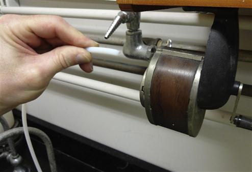
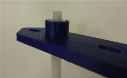
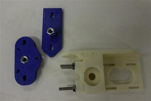
FIGURE 5.35 Mounted M6s in the holes of the extruder mount and hot end mount and the long M4s screws on the extruder body and the idler carriage.
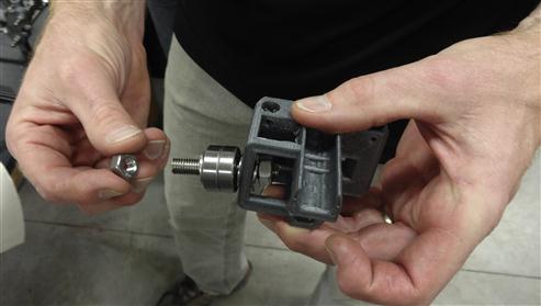
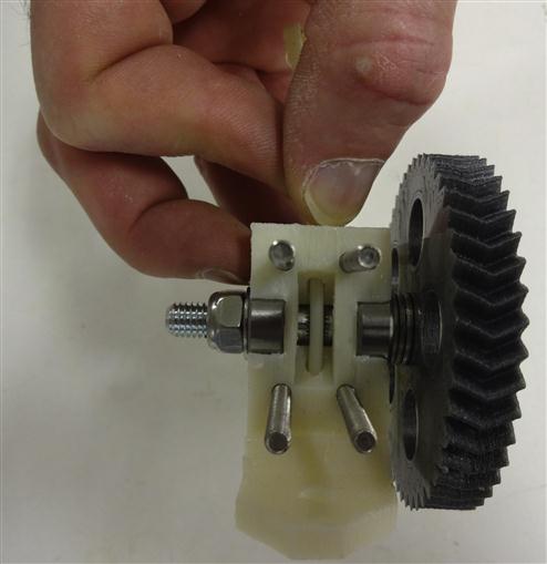
Next, mount the main large herringbone gear by taking the hobbed bolt, gear, 2–4 washers, 608 bearing and then push through extruder body, 608 bearing, washer and a lock nut. The number of washers will depend on your hobbed bolt. You want your filament to be centered on the hobbed part of the bolt (as shown in Figure 5.37). Now match up the gears (Note: This may demand a stepper motor spacer depending on the motors you obtained.). This spacer is shown in blue in Figure 5.38 and can be adjusted in OpenSCAD for perfect fit. Match the gears up and screw the stepper motor to the extruder body with two M3 screws and tighten them down. Then push the hobbed bolt out of the large gear and catch the washers as they fall. Then screw the other two M3 screws and washers down and put the hobbed bolt and washers back together. Mount it all to the frame with the M8 bolts and washers.
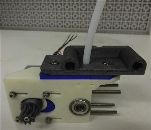
Now, turn your attention to the other end of the Bowden sheath. Screw the sheath down over the M4 nut in the extruder holder and trim off with knife to be flush with nut. Run a one-eighth drill bit through the hole as shown in Figure 5.39.
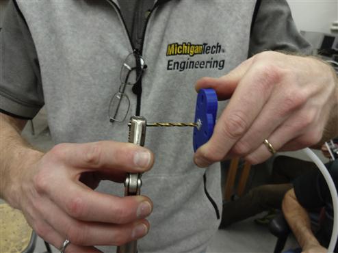
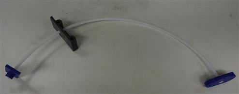
You may find this easier to do holding the drill bit with pliers.13 Put the sheath through the extruder drive mount (gray) and then screw the sheath down over the M4 nut in the drive holder (blue). Trim with knife, run the drill bit, and threw it following the same procedure in Figure 5.39. Then, run the filament through the Bowden cable and make sure all PTFE shards are removed. If you skip this step, there is a risk that you will get a plugged nozzle before you even start printing. Please note again all the blue parts in the images are in ABS to provide better protection against warping at high temperatures. You should now have the Bowden sheath completely constructed as seen in Figure 5.40.
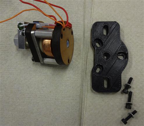
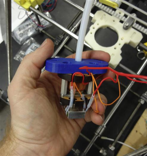
The next step is to prepare the extruder. Remove the printed plastic base on the Budaschnozzle (Figure 5.41, the base is printed in black). You may want to keep this black piece so you can direct mount your extruder to the x-axis in the future. Now attach the extruder mount (blue piece) to the Budaschnozzle using the same screws and tighten the whole Budaschnozzle down as shown in Figure 5.42. Attach the Budaschnozzle to the x-axis using two M4 × 20 screws, nuts and washers and your printer should look like it is coming together as in Figure 5.43.

5.2.9 Electronics
Assemble the BOM for the electronics as shown in Figure 5.44:

If you have never soldered before, now is your chance to learn! I recommend trying to solder two wires together first to get the hang of it. Solder the wires together tinning the surface first and do a butt joint.
When you are ready, cut the thermistor leads to have one slightly shorter than the other (a few millimeters). Get 3 ft of two conductor wires. Then cut your conductors to the same length difference. Cut 1 cm of heat shrink tubing to completely cover the first lead and a slightly larger diameter heat-shrink tube to go over the first and the other wire. String them both on the wire. Strip about 0.5 cm of wire and overlap the thermistor leads with the wire. Solder the wire to the thermistor lead by tinning the surface first—do a butt joint. Put the first heat-shrink tube down and use a lighter or heat gun to shrink it. Then solder the second wire. Finally put the longer heat-shrink tube down over the second wire and first heat-shrink tube—and shrink it in place with the lighter or heat gun.
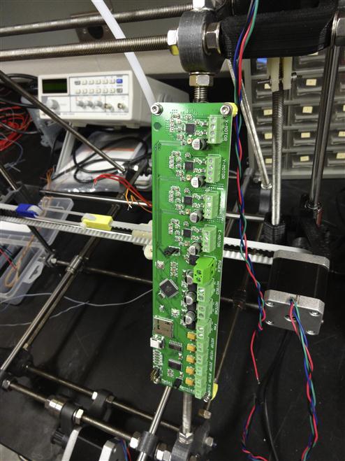
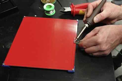
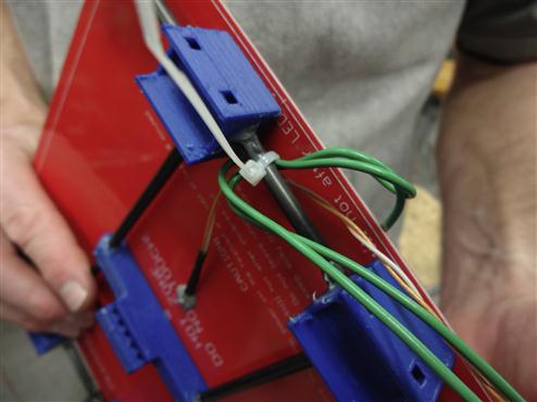
Now it is time to begin building the electrical system. Screw the Melzi mounts onto the Melzi board with M3 screws, bolts and washers. Mount the Melzi board to the right of your printer on the far side of the extruder using zip ties as shown in Figure 5.45. Next, solder 3 ft of wire to the thermistor (orange) epoxied to the heated board and solder 3 ft of wire to the front metal contact on the heated board as shown in Figures 5.46 and 5.47.
Zip tie the wires to the heated board to ensure you do not stress the soldered joints as shown in Figure 5.48. Now depending on the motors you have, you may need to solder extensions to any wires that are necessary to ensure they can reach to the Melzi without running into the moving parts. Then heat shrink tube over them to clean them up or you can braid all your wires. In general, it is a good idea to have tidy wire management and spending a few extra minutes will save you from frustration in the future when you break a connection because a wire was out of place and got pulled by the printer.
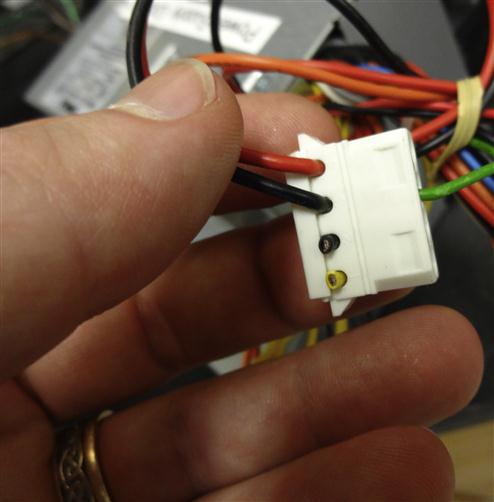
When using the Melzi board, pay particular attention to polarity of the incoming power. The board is marked and black goes to ground (gnd)! Failing to wire the board properly will risk smoking (destroying) your board. In addition, motor wiring is terminal-specific. Use a multimeter to identify what motor leads belong together (pairs will have some low resistance, like 8 Ω whereas nonpairs will be essentially open circuits). Ensure that your wires are paired by using a multimeter and measure the leads on the steppers. Black and green are a pair as can be seen in the images of Figures 5.49 and 5.50.
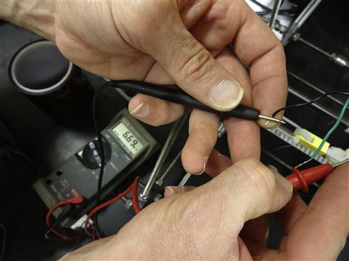
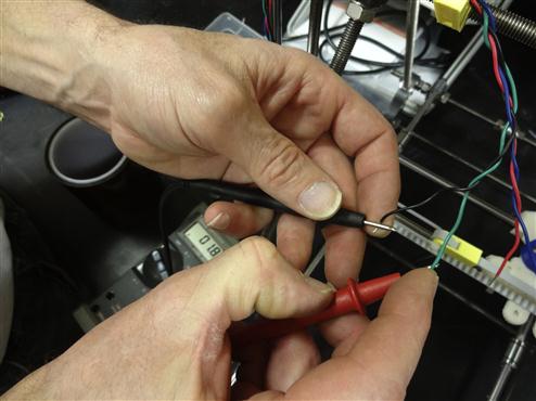
The rest of the wiring is not terminal-specific, so you do not need to worry about polarity. Once everything is wired up, check motor rotation with the interface described below and if it is wrong, swap conductor pairs.
5.2.10 Limit switches
The next step is to gather the BOM of your limit switches as shown in Figure 5.51, which consists of the following:
Three mechanical limit switches and wires, three end stop holders (printed), three M3 × 20 mm screws and three M3 washers.
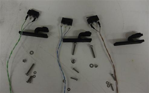
Mount your limit switches to the end stop holders. Plastiform the threads into the plastic and put on all the M2 screws. Mount the three limit switches to x-, y-, and z-axes, respectively, as shown in Figures 5.52, 5.53 and 5.54.
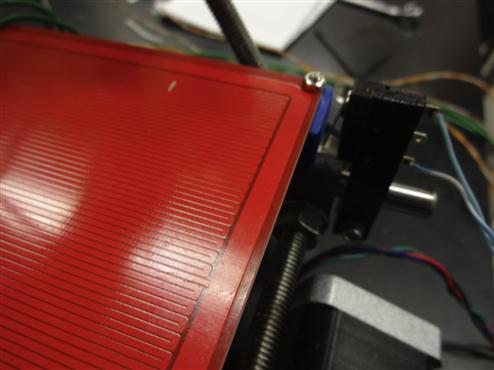
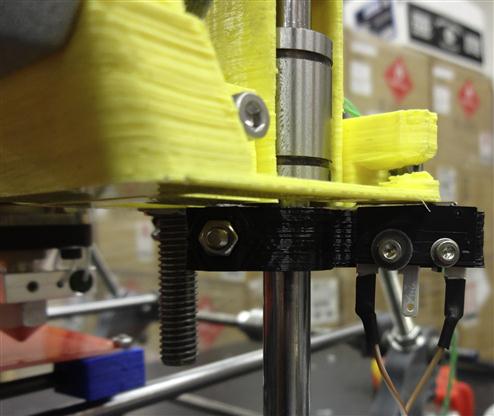
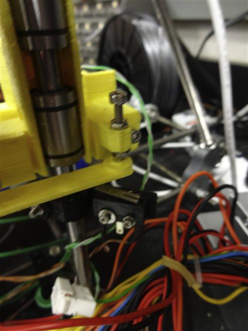
The x-switch is triggered by the x-carriage. The y-switch is triggered by the corner of the y-frame (blue) and the z-switch is right beneath the flexible arm (yellow). Put an M3 and two nuts on the flexible arm to enable you to do fine control of the z-switch.
5.2.11 Power supplies
You can purchase a power supply specifically for your RepRap, but chances are if you are in either an educational institution or an industrial lab, there are a plethora of appropriate power supplies available from old computers that are being discarded. Cannibalize an old computer or buy a power supply that provides a minimum of 15 A at 12 V. After the power supply is completely unconnected, cut off the ends of all the black and yellow (12 V) supplies, group them and solder together (as seen in Figure 5.55). Take the yellow and black bundles and extend with wire by soldering. Then plug these power lines into the Melzi Board. You will not need the other leads, but leave them on to both prevent shorts and leave room for expansion in the future (e.g. adding a cooling fan).
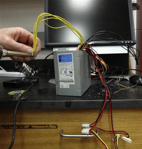
Short the green wire with black ground in order to provide the 12 V from your black and yellow as seen in Figure 5.56. Do this by simply cutting the green wire and any black wire from the 24 pin power connecter on the power supply and soldering them together. You can then put some heat shrink tubing around the solder. If your power supply has a mechanical switch on the back, a straight solder is fine; if there is no mechanical switch (i.e. you plug it in to turn it on), you may want to wire a switch between the green and black wire to turn it on and off easily.
5.2.12 Adjust the trim pots for motors
Next, find the trim pot on your board, it is located to the right of your stepper driver and below the large capacitors (below stepper driver and to the left of the large capacitor if you are looking at it while mounted on the frame). It will have a screwdriver like top surface. Notice that on the left side of the trim pot, there is a single large tab at the base and on the right side, there are two tabs. We are interested in the single left tab.14 If your board is not plugged into the USB, plug it in now. You do not need to power the entire board to adjust the trim pots. Ensure that the power selection jumpers are set to USB as well. The USB power is enough to allow for trim pot voltage readings. Next, use a multimeter and set it to DC voltage within the range for 0–1 V. Measure the voltage from the trim pot, red probe goes to the left side, and single tab of the trim pot. While the black probe goes to GRND (feel free to use the GRND from JP16). Be careful not to slip—you may short something! The voltage by factory default should be around 0.7 V or so, which is high for most motors. Melzi has a sense resistor value of 0.2 Ω, ultimately the math you need to know to set the right Vref is 0.28× (max current (A) of your motor). If you purchased the motors recommended in the BOM, it is 0.28 × 1.7 = 0.476. If you are really curious about the math behind this tuning, the Reprap wiki provides a very good overview.15
Turn the trim pot clockwise to turn down the voltage, clockwise to turn it up. Be aware there is no stopper on the trim pots. It is possible to over turn the trim pots, so please use a multimeter when adjusting. Read the voltage and adjust until proper Vref is set. You can also overshoot by a little bit (roughly within 0.1 V). Finally, plug in the power supply into the Melzi board and you are ready to start—black is ground.
5.3 Software
The software tool chain consists of three discreet parts: firmware, printer interface and slicing software (although some interfaces can also provide slicing). In short, the slicing software takes a 3-D model and converts it to g-code, which is a numerically controlled programming language that tells the 3-D printer how to make your model. The printer interface sends the g-code to the printer and the firmware interprets the g-code into movements.
5.3.1 Firmware
Firmware is really a software that resides on the printer controller board (in this case the Melzi). The firmware (1) interprets g-code into motion, controlling the motors, the temperature of the hot end and heated build platform, (2) takes notice when limit switches are activated and (3) echos responses when commands are executed or a problem occurs. Ideally, you will only need to configure your firmware and upload onto the controller board once and the printer is then ready for use. If you are using a 3-D printer that is known to be functional already, then it is unnecessary to complete the following steps pertaining to firmware configuration and uploading. Practically, firmware will be occasionally upgraded, so the practice of configuration and uploading is worth understanding.
5.3.2 Printer interface
The printer interface is software that runs on the host computer attached to the printer via a USB cable. It provides an interface for controlling the printer: setting temperatures, moving axes, starting print jobs, etc. The printer interface essentially converts interactions with it into g-code—when a button or linked image is clicked or text is entered into the printer interface, it is converted into g-code that is then sent to the printer firmware for interpretation into some action.
5.3.3 Slicer
A slicer is software that converts a solid model (typically an STL file type) into the g-code that the printer firmware can interpret into action. After slicing a model, the g-code is either loaded onto a micro-SD card, which is then inserted into the printer control board and then activated through the printer interface or the g-code is loaded into the printer interface and then transmitted to the printer controller board in small chunks over via the USB connection.
5.3.4 Software sources
There are five software packages you will need to download (three for the firmware and one each for the printer interface and slicing). All the software is free and open source:
1. Firmware: Marlin.16
2. Arduino IDE.17
3. Melzi driver18 and instructions.19
4. Printer interface: Pronterface.20
5. Slicing software: Cura.21
The primary repository for 3-D printable designs, as of this writing, is Thingiverse,22 although it should be noted there is an ongoing discussion for making a more appropriate central repository of enabling innovation.23 I keep two collections of designs updated that will be of most interest to the readers of this book:
Both collections are growing rapidly. You can also search Thingiverse by keyword, or by browsing click Explore, Categories, Learning. Unfortunately, as of this writing, Thingiverse only has learning broken down into the following categories: biology, engineering, math, physics and astronomy. If there is something that you want to print that is not up yet, please design it yourself and post it!
5.3.5 Controller board installation
Although, I would strongly recommend that you move your computer to an open-source operating system like Linux (such as Debian26or Linux Mint27) and you can also use your RepRap with a Windows or Apple computer. If you are not using Linux and a package installer to install Arduino easily, you can download the Arduino integrated development environment (IDE) for your operating system28 and follow their Getting Started guide for your operating system. Once you are able to open the Arduino IDE, download the Melzi driver from the above link and follow instructions to save the driver in the Arduino folder. Upon restarting the Arduino IDE, the Mighty 1284P 16 MHz using Optiboot should be an option under Tools → Board. Select it.
For a Linux installation, plug the Melzi board into an available USB port on your computer using the supplied cable. Install the arduino and arduino-mighty-1284p packages using your package manager. Upon starting the Arduino IDE, the Mighty 1284P 16 MHz using Optiboot should be an option under Tools → Board. Select it.29
For the windows driver installation, plug the Melzi board into an available USB port on your computer using the supplied cable. If prompted to install a driver, select manual installation and locate the driver in Arduino folder under drivers under “FTDI USB drivers”
For an Applie installation, follow all operating system instructions, no extra driver needed.
Again on any operating system other than Debian, you will need to ensure mighty-1284p installed, so Arduino will understand the board.
5.3.6 Firmware configuration
The firmware is written for Arduino and Arduino-based controllers in a programming language known as C++ (as discussed in detail in Chapter 4). The firmware used for the MOST RepRap builds is Marlin, available at the link above. To install and configure, do the following:
1. Download Marlin firmware from the above link and unzip into a logical and memorable location. As in Chapter 4, it is easier if this location is the sketchbook folder.
2. Open the Arduino IDE and then open Marlin.pde from the File → Open… option, navigating to the location where Marlin was unzipped to.
3. Note that the IDE opens a number of different tabs, select the tab Configuration.h.
4. Locate the line #define BAUDRATE and replace number with 115200.
5. Scroll down the page and locate #define MOTHERBOARD and replace the number with 63 to set the firmware for the Melzi board.
6. Scroll further down and locate the line #define TEMP_SENSOR_0 and set it equal to 1.
7. Set #define TEMP_SENSOR_BED = 4.
8. Locate the line starting with #define X_ENDSTOPS_INVERTING, set it and the two following (Y and Z) to false.
9. Locate the line starting #define INVERT_X_DIR. Follow the instructions in the remarks for the six lines starting at that entry for Mendel printers and geared extruder.
10. Scroll further down locating the line #define DEFAULT_AXIS_STEPS_PER_UNIT. The values in the parentheses represent an array; a number for each axis is separated by a comma. These settings tell the printer how many steps are required to move a millimeter of whatever the axis moves (x, y and z move part or hot end, E moves filament). Using the RepRap calculator from Josef Prusa,30 we can figure out how many steps are required for x, y and z. The motors are 0.9°/step (although most users use 1.8°/step motors as they work better and can handle more torque) and the Melzi board is set to use 1/16 microsteps, yielding 106.667 for the 12 tooth pulleys on the x- and y-axes and 5120 for the z-axis. Trial and error has yielded a setting of 1500 for E. For 400 steps/revolution motors, this entry should be (106.667, 106.667, 5120, 1500); for 200 steps/revolution motors, it should be (53.333, 53.333, 2160, 750). Only if using 400 steps/revolution motor: locate the line #define DEFAULT_MAX_FEEDRATE and set the third number in the list to 2.
11. Save the updates (File → Save, ctrl-S or click the down arrow in the tool bar) and upload to the board (File → Upload, ctrl-U or click the right arrow in the tool bar). Watch the prompt cues at the bottom of the window and wait for the message “Done Uploading”.
12. Once the firmware is uploaded to the controller board, open the serial monitor (Tools → Serial Monitor or the magnifying glass on the tool bar). Set the communication rate to 115200 and click the reset button on the Melzi controller board. The current printer settings should be echoed on the serial monitor screen.
5.3.7 Printer interface and slicer
The Melzi board uses a printer interface to send print jobs to the controller. Download and install Pronterface from the above link (or simply install it with the package manager if using Linux). Note that there are precompiled binaries for different OSs if you scroll down the page; if you are not using Linux, it is easiest to simply download the appropriate one for your operating system. Once Pronterface is running, select the communication port, set the speed to 115200 and click the connect button. A message will be echoed by the controller indicating that the printer is online if the connection is successful. You can test this by trying to move the printer head in the x- or y-direction.
Three-dimensional solid models are sliced into individual layers for the printer by a slicing program (slicer). Download and install Cura from the link above. A screenshot of Cura is shown in Figure 5.57 and it is relatively straightforward to use. There are also other slicing programs available and you may want to try them out to see what works best for your group.31

5.4 Printing for the First Time
You are now ready to print for the first time. Load the filament through the tube while the hot end is still cold. Ensure that your motor leads are all wired correctly by (1) opening Pronterface, (2) connecting to the printer and using the x, y, and z controls to test directionality. Do this in small steps—particularly for the z-axis. If any of the motors are spinning the wrong direction, turn off the power so you do not destroy the stepper driver, and then switch the leads.
5.4.1 Level the z-axis
Position the hot end to the far right of the board and move the nozzle down until it is two paper widths from the stage. This is the home position. You can adjust this position to perfection using a combination of moving the z-end stop, the z-micropositioner (Figure 5.58), and the bolts holding up the z-axis.
Then move the hot end to the left of the stage and adjust the bolts on the left z-axis to make it level with the right. The hot end should go from the left to right and back the exact same height from the bed.
5.4.2 Print fantastic and inexpensive scientific hardware
You are now ready to print. You can download your first designs from Thingiverse or another repository (e.g. grabcad, github.com, 3Dhacker.com, appropedia.org, etc.). The next chapter has many examples, but first consider the simple open-source lab jack32 shown in Figure 5.59.
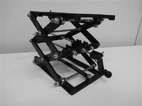
This lab jack was designed by MOST after we had received an absurd $1000 quote for one to help align an analytical instrument to test solar photovoltaic devices. Lab jacks come in highly variable precision and quality as there are high-precision jacks available in the hundreds (or even a thousand!) all the way down to $25 for poorly built toy lab jacks on the Internet. As you can see in Figure 5.59, the labjack is constructed from a few relatively easy prints in PLA, ABS or other thermoplastic (e.g. no overhangs, advanced materials or complicated multihead printing is necessary). The remainder of the BOM is common screws and bolts that you are likely to have on hand having just built a RepRap and ordered nuts and bolts by the bag. The design shown here is highly customizable and perhaps offers better value than even some of the high-end lab jacks as you can control the precision and the frames by altering the design. Thus you can customize the lab jack for your specific application and build in holders, clips, bolt holes, etc. to match the specific requirements of your experiments.
The RepRap can print a lot more than a lab jack and currently there are hundreds of components of scientific instruments proliferating on the Internet. The MOST RepRap described above can be built by two people in a day for under $600. As the investment in a RepRap is capable of repaying itself after a few hours of printing even common scientific hardware, it is likely to become an indispensable resource for most laboratories as more sophisticated and customized open-source scientific tools are developed. In Chapter 6, we will look at many examples of open-source scientific hardware using RepRap printable components (or entire tools) in physics, engineering, environmental science, biology, and chemistry. This list is expanding rapidly and is meant to provide a snapshot of the current abilities to inspire you to join the open-source scientific hardware community and create your own equipment for the benefit of all of science.
References
1. Upcraft S, Fletcher R. Assem Autom. 2003;23.
2. Gibson I, Rosen DW, Stucker B. Phys Procedia. 2010;5.
3. Petrovic V, Gonzalez JVH, Ferrando OJ, Gordillo JD, Puchades JRB, Griñan LP. Additive layered manufacturing: sectors of industrial application shown through case studies. Int J Prod Res. 2011;49(4):1061–1079.
4. Gebhardt A, Schmidt F, Hötter J, Sokalla W, Sokalla P. Phys Procedia. 2010;5.
5. Crane NB, Tuckerman J, Nielson GN. Self-assembly in additive manufacturing: opportunities and obstacles. Rapid Prototyping J. 2011;17(3):211–217.
6. Economist 21 April, 2012 [special issue].
7. Jones R, Haufe P, Sells E. RepRap - the replicating rapid prototyper. Robotica. 2011;29(1):177–191.
8. Gershenfeld N. Fab: the coming revolution on your desktop – from personal computers to personal fabrication. New York, NY: Basic Books; 2005.
9. Corney J. The next and last industrial revolution? Assem Autom. 2005;25(4):257.
10. Malone E, Lipson H. Fab@Home: the personal desktop fabricator kit. Rapid Prototyping J. 2007;13(4):245–255.
11. Pearce JM, Blair CM, Laciak KJ, Andrews R, Nosrat A, Zelenika-Zovko I. 3-D printing of open source appropriate technologies for self-directed sustainable development. J Sustainable Dev. 2010;3(4):17–29.
12. Bradshaw S, Bowyer A, Haufe P. The intellectual property implications of low-cost 3D printing. ScriptEd. 2010;7(1):1–27. doi 10.2966/scrip.070110.5.
13. Holland D, O’Donnell G, Bennett G. Open design and the RepRap project. In: 27th International Manufacturing Conference. 2010;97–106.
14. Weinberg M. It will be awesome if they don’t screw it up. 2010; In: http://nlc1.nlc.state.ne.us/epubs/creativecommons/3DPrintingPaperPublicKnowledge.pdf; 2010.
15. Cano J. The Cambrian explosion of popular 3D printing. Int J Artif Intell Interact Multimedia. 2011;1(4):30–32.
16. Pearce Joshua M. Building research equipment with free, open-source hardware. Science. 2012;337(6100):1303–1304.
17. Hodgson G. Interview with Adrian Bowyer. RepRap Magazine 2013;(Issue 1):8–14.
18. Bowyer Adrian. Wealth without money. 2004; RepRap Wiki. Available from: http://reprap.org/wiki/Wealth_Without_Money; 2004.
19. RepRap wiki User: Emmanuel, The RepRap Family Tree - Timeline 2006–2012 v4.0 14-04-2012. Available from: http://www.reprap.org/wiki/RepRap_Family_Tree.
20. Sells E, Bailard S, Smith Z, Bowyer A. RepRap: the replicating rapid prototype maximizing customizability by breeding the means of production. Cambridge, MA: MCPC 2007; 2007; No. MCPC-045-2007.
21. Arnott R. The RepRap project – open source meets 3D printing. In: Computer and information science seminar series. 2008.
22. Kentzer J, Koch B, Thiim M, Jones RW, Villumsen E. An open source hardware-based mechatronics project: the replicating rapid 3-D printer. In: 2011 4th International Conference on Mechatronics. 2011;1–8.
23. Arduino homepage. 2013; Available from: http://www.arduino.cc/; 2013.
24. Baechler Christian, DeVuono Matthew, Pearce Joshua M. Distributed recycling of waste polymer into RepRap feedstock. Rapid Prototyping J. 2013;19(2):118–125.
25. Gonzalez-Gomez J, Valero-Gomez A, Prieto-Moreno A, Abderrahim M. A new open source 3D-printable mobile robotic platform for education. Adv Autonomous Mini Robots 2012;49–62.
26. Anzalone GC, Glover AG, Pearce JM. Open-source colorimeter. Sensors. 2013;13(4):5338–5346.
27. Leigh SJ, Bradley RJ, Purssell CP, Billson DR, Hutchins DA. A simple, low-cost conductive composite material for 3D printing of electronic sensors. PLoS One. 2012;7(11):e49365.
28. Redlich TOBIAS, Wulfsberg JP, Bruhns FL. Virtual factory for customized open production. In: Tagungsband 15th International Product Development Management Conference. 2008; Hamburg.
29. DeVor RE, Kapoor SG, Cao J, Ehmann KF. Transforming the landscape of manufacturing: distributed manufacturing based on desktop manufacturing (DM)2. ASME DC J Electron Packag. July 18, 2012;134. doi 10.1115/1.4006095.
30. Moses Matt, Yamaguchi Hiroshi, Chirikjian Gregory S. Towards cyclic fabrication systems for modular robotics and rapid manufacturing. Proc Rob: Sci Syst 2009.
31. Bayless Jacob, Chen Mo, Dai Bing. Wire embedding 3D printer. 2010.
32. Bhatia Sangeeta N, Chen Christopher S. Rapid casting of patterned vascular networks for perfusable engineered three-dimensional tissues. 2012.
33. Zhang C, Anzalone NC, Faria RP, Pearce JM. Open-source 3D-printable optics equipment. PLoS ONE. 2013;8(3):e59840.
1In Wealth Without Money, Bowyer writes: “The self-copying rapid-prototyping machine will allow people to manufacture for themselves many of the things they want, including the machine that does the manufacturing. It is the first technology that we can have that will simultaneously make people more wealthy, while reducing the need for industrial production…” [18].
2MOST RepRap Build http://www.appropedia.org/MOST_RepRap_build For the two person build use: http://www.appropedia.org/MOST_RepRap_parallel_build_overvie.
3MOST RepRap User Experience http://www.appropedia.org/MOST_HS_RepRap_user_experience.
4RepRap Forums http://forums.reprap.org/.
5RepRap wiki http://www.reprap.org.
6MOST RepRap Printable component STL files—http://www.thingiverse.com/thing:92321.
7If you do not know anyone with a 3-D printer and do not have any other form of rapid-prototyping or 3-D printing services at your institution, there are numerous commercial 3-D printing services available along with individuals in the RepRap forums that will print the components out for you for a nominal fee. For example, see http://forums.reprap.org/list.php?175.
8Drill bit handles http://www.thingiverse.com/thing:91035.
9http://reprap.org/wiki/IRC. It should be noted that this is an anonymous Internet forum and just like any other anonymous forum, you should not take offense or “feed the trolls” that sometimes interject less than useful comments. The majority of RepRap IRC users are experienced and helpful.
10Make sure you have the feet facing the correct direction at the bottom of the triangle.
11Make sure you have added the nuts and springs to the threaded rod before putting on the x-axis.
12Carbon fiber rods are from goodwinds.com/merch/list.shtml?cat=carbon.pultrudedcarbon item no. 020961.
13If you have access to a 3-D printer already, you can also print out these handy drill bit handles. http://www.thingiverse.com/thing:91035.
14This is easiest to accomplish with two people—one measures while the other adjusts.
15Stepper motor driving board http://reprap.org/wiki/Pololu_stepper_driver_board.
16Marlin https://github.com/ErikZalm/Marlin/tree/Marlin_v1/Marlin.
17Arduino IDE http://arduino.cc/en/Main/Software.
18Melzi board https://github.com/maniacbug/mighty-1284p.
19Melzi instructions http://matterfy.com/pages/how-tos.
20Printrun https://github.com/kliment/Printrun.
21Cura http://daid.github.com/Cura/.
22Thingiverse http://www.thingiverse.com/.
23Improved digital design database http://www.thingiverse.com/thing:30880.
24Collection of open-source scientific tools that re 3-D printable [16] http://www.thingiverse.com/jpearce/collections/open-source-scientific-tools.
25Collection of open-source optics tools that are 3-D printable [33] http://www.thingiverse.com/jpearce/collections/open-source-optics.
26Debian http://www.debian.org/.
27Linux Mint http://www.linuxmint.com/.
28Arduino softwarehttp://arduino.cc/en/main/software.
29There may be a warning that you should be a member of the dialout group. If so, follow the instructions.
30RepRap Calculator http://calculator.josefprusa.cz/.
31For example, Slic3r, Skeinforge, Repsnapper, RepRapPro Slicer, etc. For direct links, see http://reprap.org/wiki/Useful_Software_Packages#Software_for_dealing_with_STL_files.
32Open-source labjack http://www.thingiverse.com/thing:28298.