Digital Designs and Scientific Hardware
Abstract
Just as the power of the open-source design paradigm has driven down the cost of software to the point that it is accessible to most people, the rise of open-source hardware is poised to drive down the cost of doing experimental science to expand access to everyone. This chapter provides a selection of concrete examples of exceptionally low-cost open-source scientific tools for physics, engineering, biology, environmental science and chemistry. Using the combination of open-source CAD, 3-D printing, and microcontrollers (OpenSCAD, RepRap 3-D printing and Arduino automation), the following research tools have been designed, built and are described in this chapter: (1) a multicomponent open-source optics library, (2) polymer laser welding system, (3) radiation detector, (4) oscilloscope, (5) colorimeter, (6) pH meter, (7) PCR machine, (8) centrifuge, (9) spectrometer, and many other small useful tools.
Keywords
3-D printing; Centrifuge; Colorimeter; Laser welding; Oscilloscope; OpenSCAD; Optical equipment; PCR; pH meter; pH; Radiation detection; Spectroscopy
6.1 OpenSCAD, RepRap and Arduino Microcontrollers
This chapter provides examples of scientific equipments produced using the open-source hardware (OSH) paradigm. This section will provide the basic background in the use of the three primary toolsets for OSH equipment. First, the use of parametric open-source designs using an open-source computer-aided design (CAD) package is described to customize scientific hardware for any application. This tool will then be used as the example for many scientific and engineering disciplines throughout the chapter whenever possible. Second, details are provided on how to use the open-source 3-D printers discussed in Chapter 5 to fabricate both the primary components of scientific tools and how to construct complex, multicomponent engineering and scientific devices. Finally, open-source electronic prototyping platforms, such as were discussed in Chapter 4, will be demonstrated to control complex scientific devices saving your lab time, money, and improving your research productivity.
6.1.1 OpenSCAD
Although the RepRap can print STereoLithography (STL) files generated from any CAD package, the majority of the physical designs in this chapter were developed in the free and open-source OpenSCAD1 as it is currently the defacto “maker” standard.2 It is the most flexible currently available open-source CAD package and you do not necessarily need to know anything about conventional CAD. OpenSCAD is an open-source, script-based CAD application. It is used by writing simplistic code to describe the geometric specifications of the required object by using three primitive shapes (cylinder, sphere and cube) and complex polygons using the polygon, polyline and the 2-D and 3-D extrusion commands. If you understand the basic geometry and Boolean logic, you should not have any trouble getting started. If you have written any kind of computer code before, then this will be easy. The real power of OpenSCAD is that it allows for parametric designs, which is the ability to alter a design to specifications by changing the parameters of the geometry of an object. This allows changes to be made to the design easily and quickly by simply changing the value of user-defined variables. Simply put—if you change a single number in the code—you can immediately have a new customized design. This would be great enough on its own, but Thingiverse.com, the repository that now holds well over 100,000 OSH designs, has a built in Customizer App that enables you make it absurdly easy for others to customize your designs if they are written in OpenSCAD. The would-be custom users of your design do not even need to go into OpenSCAD to alter the design, they can make the change from their browser window. To illustrate briefly how OpenSCAD works, consider the code for a simple gasket3 below:
//Customizable Gasket
// This is a simple open-source parametric gasket
//CUSTOMIZER VARIABLES
//Defines the height of the gasket
gasket_thickness=1; //[1:10]
//Defines the gasket outer diameter
gasket_outer_diameter=2; //[2:100]
//Defines the gasket inner diameter
gasket_inner_diameter=1; //Numeric value smaller than Gasket Outer Diameter
//CUSTOMIZER VARIABLES END
module gasket()
{difference()
{cylinder(h=gasket_thickness, r=gasket_outer_diameter∗2, center=true, $fn=100);
cylinder(h=gasket_thickness, r=gasket_inner_diameter∗2, center=true, $fn=100);
}
}
gasket();
This code produces a simple gasket as shown in Figure 6.1.
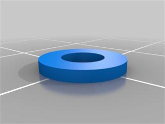
In this code, anything following a line that begins with // is commented out and ignored when generating the STL image. The gasket is developed by making two simple shapes (cylinders) and subtracting one from the other using the difference command. For a complete tutorial on how to use OpenSCAD, see the OpenSCAD User Manual,4 which is an open wiki book and thus constantly updated and improved. Although making a simple gasket could be accomplished in less lines of code and comments, this code is written to be as useful for others as possible. First, it is well documented explaining what every variable is. In addition, it is put in the format to be able to be used for the Thingiverse customizer.5 When the code is opened in the customizer, it looks like Figure 6.2.
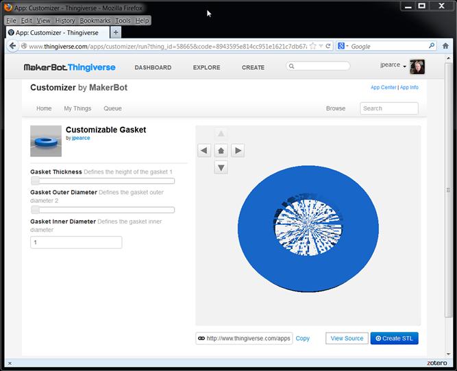
Finally, the code is set up as a module so others can copy it and put it directly into a more complex design. This way anyone wishing to make a custom gasket can adjust the size in the interface and does not even need to go down into the code. This may seem like overkill for this simple design, but as the code becomes more complex, this is a really nice favor to do for those who may need it in the future (may be even yourself).
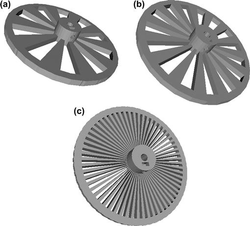
To illustrate the utility of parametric design for a scientist, consider an optical chopper wheel, which modulates the frequency of a light beam. For a given chopper wheel setup, the target frequency can be adjusted by the number of slots in the chopper wheel. Normally, this involves the separate purchase of a new wheel for each experiment, and the experimenter does not always know beforehand what the optimal operational frequency is for a given application. A parametric design from OpenSCAD is shown in Figure 6.3, where the slot number for an open-source optical chopper wheel6 has been adjusted by changing a single variable in the code from (a) 10, (b) 15 and (c) 60 slots providing ranges of chopper frequency of 20 Hz–1 kHz, 30 Hz–1.5 kHz, and 120 Hz–6 kHz, respectively. OpenSCAD directly exports the geometry to an STL file, which is used for 3-D printer open-source slicing programs (e.g. Skeinforge,7 Cura8 or Slic3r9 as discussed in the last chapter), which is in turn transformed to g-code, which provides the vectors for tool path (3-D printer extruder head).
6.1.2 Open-source 3-D printers
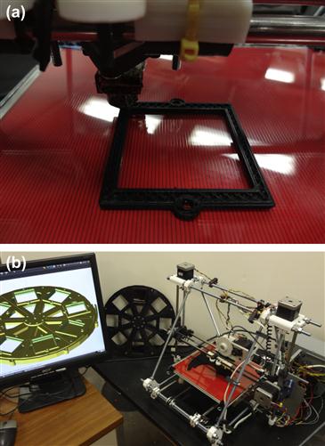
The development of open-source 3-D printers like the RepRap10 [1], the streamlined design of which as shown in Chapter 5 can be constructed for <$600, have made the cost of rapid prototyping accessible to most university laboratories [2]. RepRap’s open-source and self-replicating nature (approximately 50% of its own parts can be self-printed) makes it an extremely useful platform for open-source fabrication and maintenance of laboratory equipment. The printing process for the additive layer manufacture of scientific experimental components discussed in this chapter is a sequential layer deposition. The RepRap extruder intakes a filament of the working material,11 heats it, and extrudes it through a nozzle where deposits a 2-D layer of the working material, then the Z (vertical) axis will raise, and the extruder will deposit another layer on top of the first. In this way, it can build three-dimensional models from a series of two-dimensional layers [3]. Figure 6.4(a) shows the detail of a RepRap printing out a component of a filter wheel system,12 which will be discussed in more detail below. Figure 6.4(b) shows another component of the same filter wheel printing, and also displays the assembly in OpenSCAD on a computer running only open-source Linux software. These models can be customized for a given optical setup using OpenSCAD and printed.
6.1.3 Open-source microcontrollers
The majority of the current versions of the RepRap are controlled by an Arduino microcontroller board (or a spin-off microcontroller board), which is prototyping platform based on the ATMEL ATmega328, a high-performance, low-power AVR 8-Bit microcontroller. Arduino microcontroller boards13 are a family of open-source, low-cost integrated circuits that contain a core processor, memory and analog and digital input/output (I/O) peripherals. As shown in Chapter 4, Arduino microcontroller boards are relatively easy to use. Thus, they have been applied in a vast number of science and engineering areas including, for example, optical tools such as holographic microscope [4], portable system for high-speed multispectral optical imaging [5], and an light-emitting diode (LED) stimulator system for vision research [6]. Here the automation capabilities of the Arduino can be combined with the rapid prototyping of the RepRap to make sophisticated, customized equipment such as an automated filter wheel changer printing shown in Figure 6.4(a) and (b).
6.2 Physics: Open-Source Optics
This section introduces a library of open-source 3-D-printable optics equipment, which can be used as a flexible, low-cost public-domain tool set for developing both research and physics teaching optics hardware [7]. Overall, this section describes open-source optics development, system requirements, features, advantages, and known limitations. This same model can be applied to other physics-related research tools and equipment.
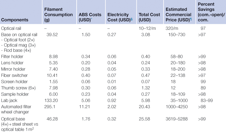
The open-source optics library is built from standard low-cost parts available in most hardware stores and customizable printed parts. First, an optical rail is fabricated from an open-source aluminum extrusion system called OpenBeam14 as shown in Figure 6.5.
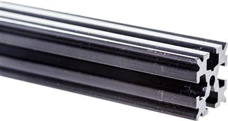
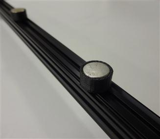
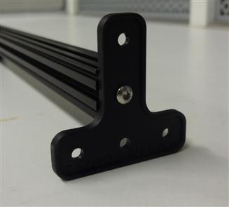
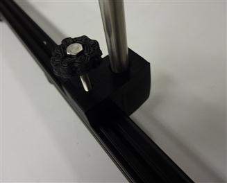
An optical rail is a long, straight, sturdy rail onto which optical components such as light sources and lenses can be bolted down and easily shifted along the length of the rail. Commercial optical rail sells for around $380/m ($115/ft), while OpenBeam is available from $10–12/m. The OpenBeam system is an open-sourced, miniaturized t-slot construction system that utilizes standard metric (M3) nuts and bolts to connect to an extruded 1 m aluminum rod (M3s can also be screwed into the center hole at the end).15 The OpenBeam is converted into an optical rail using a printable magnetic base16 (Figure 6.6), which holds the beam securely on a steel table or desk. For those not using metal tables, two OpenBeam T-brackets can either be purchased or printed to mount to any nonmetallic surface17 (Figure 6.7).
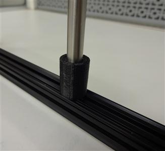
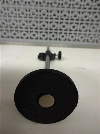
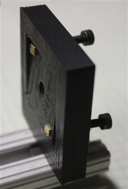
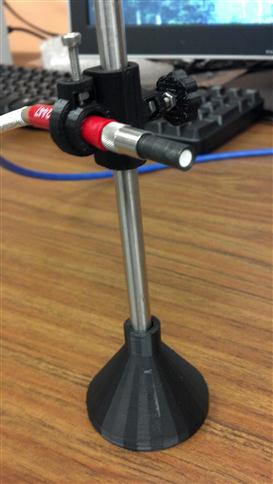
Optical components are attached via 8-mm-diameter smooth rods centered directly above the beam using a simple rod holder18 (Figure 6.8) or via an offset rod holder19 (Figure 6.9) depending on your experiment. In some experimental setups, a vibration-isolated optical table is a necessity; however, for many experiments, this is costly overengineering. While avoiding the substantial cost of an optical table, some optical experimental setups with a nonlinear experimental optical setup can be fabricated using a magnetic optics base20 as seen in Figure 6.10, which has a small cylinder opening in the bottom meant to glue in a magnet. If your RepRap is highly tuned, you can actually use a simple press fit to eliminate the need for any glue. The optics base quasi-permanently holds the position of the optical component on a magnetic surface with more flexibility than a standard optical table although not as much stability. It should be pointed out again here that all the components shown are parametric in the OpenSCAD design. So, for example, other researchers can easily alter the design shown in Figure 6.10 to hold a smaller or larger magnet and a smaller or larger smooth rod.
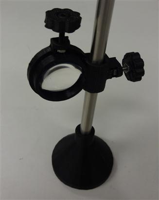
Numerous components can then be coupled to the 8-mm-diameter smooth rods and adjusted in the z-vertical axis to build up an optical assembly including a static filter or lens square21 (Figure 6.11) or circular holder22 (Figure 6.12), kinematic mirror or lens holder23 (Figure 6.13), static fiber-optic holder24 (Figure 6.14), screen holder25 (Figure 6.15) and sample holder26 (Figure 6.16). The filters in the square holders are fixed in position using M3 screws and nuts and a filter bracket, while for the circular holder, a set screw is applied as shown in Figure 6.12.
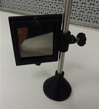
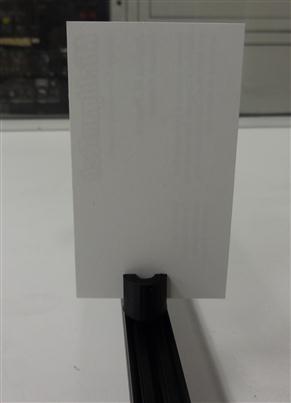
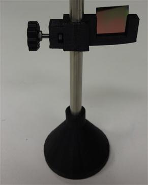
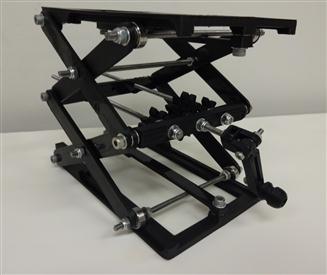
Both holders can be adjusted for other sizes of filters or lens easily using OpenSCAD. The kinematic mirror or lens mount shown in Figure 6.13 was developed by Thingiverse user ordaos and is partially parametric design used for steering optics. It contains a living hinge in one corner and two magnets in the adjacent corners, which are attracted to a pair of set screws used to adjust the mirror angle. The static fiber-optic holder was designed to hold a 7.7-mm-diameter fiber-optic cable. The screen holder is designed to support a screen or card and can be mounted on optical rail with an M3 screw–nut pair. This semiconductor sample holder shown in Figure 6.16 is designed to hold a semiconductor wafer piece on a smooth 8-mm-diameter rod (again leftover parts from RepRap builds covered in the last chapter). It allows you to change samples easily using tweezers with only one hand. More complex, multicomponent optics equipment setups can also be fabricated using this method such as an open-source lab jack,27 which is a height-adjustable platform for mounting optomechanical subassemblies as seen in Figure 6.17. Again, you can easily adjust or customize the platforms of the lab jack to hold any other type of mount for your own experiments. This makes the open-source lab jack far superior in terms of customized utility to the standard ones that in general are just simple flat platforms.
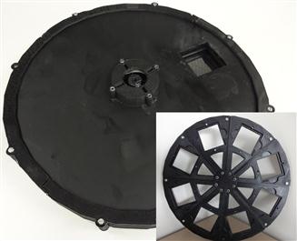
3-D printing and the Arduino can be combined to create automated dynamic optics systems such as the open-source parametric filter wheel28 shown in Figure 6.18. This version of the device has a printable wheel with eight filter slots equally spaced by 45°, an Arduino Uno microcontroller, a stepper motor, a discrete optical switch flag, a sensor composed of an output, two ends and a light beam that goes from an end to the other. When the light beam is blocked, the output signal changes depending on the logic used (e.g. from high to low). Through a computer interface, the user can set the wheel position to the desired filter by clicking on the buttons displayed on the screen, also an indicator provides the current position of the filter wheel. The user’s input is read by the Arduino’s serial communication port, the optical switch flag denotes the filter wheel’s origin (e.g. assuming the filters are indexed from 0 to 7, the filter 0 is detected when it passes through the sensor). Each time the device is turned on or restarted, it rotates until it finds the origin. Using the current location of the filter stored inside the memory and the optical switch flag information as feedback, the Arduino interprets the input and drives the stepper motor following the logic created by the program code until the desired filter is positioned and the input matches the output. The logic always uses the shorter path until the next filter by calculating the difference between the next and the current filter, and always passes through the origin when it is possible to maintain calibration. This automated filter wheel, which only costs about $50 to make, saved my laboratory from spending $2500 + shipping. It was exactly what my lab needed and having made the initial investment in the design, we will never need to purchase one again.
6.2.1 Benefits of the open-source approach for physics research
The OpenSCAD designs and STL files for the entire open-source optics library were posted on Thingiverse (see footnotes for direct links above), a digital design repository, which also provides links to all the control software for the Arduino. In addition, I maintain a Thingiverse collection of open-source optics equipment that is routinely updated as researchers from all over the world share their own designs.29 For example, Thingiverse user kovo recently shared an even lower cost optical rail system, which could be useful for many experimenters. His system uses 3-D printed optical mounts for extruded aluminum angle, which can be purchased from most local hardware stores.30 The aluminum angle design is shown in Figure 6.19. This system would be of particular use to anyone working in remote communities without shipping access to specialized extrusions like OpenBeam. Similarly, simple designs can also be coupled together to make much more complicated systems. Consider the optics setup in Figure 6.20, where Thingiverse user ordaos uses several of the kinematic mounts shown in Figure 6.13 to make a Michelson interferometer.
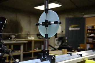
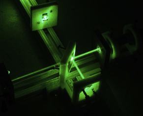
FIGURE 6.20 Michelson interferometer fabricated with 3-D printable kinematic mounts and extruded rails.
Any researcher, scientist, or teacher, whether professional or amateur with access to a low-cost open-source 3-D printer, can utilize the designs to radically reduce the cost of optical support equipment as summarized in Table 6.1.
Table 6.1
Material and Energy Costs Associated with Open-Source Optics Component Fabrication Compared to Commercial Prices and Percent Savings
∗The price of 3 mm ABS filament is $0.038/g. Source: 3D printer stuff. Available from: http://www.3dprinterstuff.com/shop/page/4?shop_param= [accessed 19.10.12].
§The national average cost of electricity is 11.53 cents/kWh. Source: U.S. Energy Information Administration. Source: Available from http://www.eia.gov/beta/enerdat/#/topic/7?agg=0,1&geo=g&endsec=vg&freq=A&start=2008&end=2011&charted=1 [accessed 19.10.12]. The electricity cost derived from multimeter is 0.006925 kWh/g (using 3 mm ABS) assuming a Prusa RepRap 3-D printer.
¶Commercial prices were derived from website data from various vendors including Edmund Optics, Thorlabs, McMaster-Carr, AutoMate Scientific, and Pasco.
As can be seen in Table 6.1, cost reductions over 95% are common with some components representing only 1% of the current commercial investment. Even if the RepRap build discussed in Chapter 5 represents too steep of a learning curve or time commitment (∼24 h build time for one person, or 8 h for two) than your laboratory or school can invest, dozens of small companies offer kits or prebuilt open-source 3-D printers, which are easily found on the Internet. With even assembled RepRap printers costing around US$1000 [8], printing a relatively simple optics setup or even a single filter wheel easily recoups the investment. The filament is also available on the web from dozens of suppliers (in various colors and polymer types) and our recent work has investigated the use of recycled polymer extruders (called “recyclebots”),31 which decreases the cost of the material for the components by another order of magnitude [9,10].
The ability to custom manufacture optics equipment to specifications within a university, government, or industrial laboratory not only ensures that the components are exactly what you as the researcher need, but it also saves time. For example, it is much faster to print a predesigned component than to go to a lab supply store if there is one in the area or even order online with next-day shipping. The value of timely access to experimental equipment can hardly be overstated for researchers as delays due to out-of-stock equipment and shipping are well-known problems for all researchers doing advanced experimental work. If a critical component is out of stock from suppliers, designing and printing it within a lab can literally save weeks. As the components of the open-source optics library are parametric, customizing the part and having a finished design ready for printing is extremely fast and easy. However, it should be pointed out that time savings are highly component specific. Three-dimensional printing in general is more time-consuming on a per-part basis than any mass manufacturing process, but there are savings associated with ordering, stocking and shipping for self fabrication. In addition, if a new component of significant complexity needs to be designed from the beginning, this can be more time-consuming than simply ordering a commercial component. However, if the component needs to be customized, self-fabrication again can be and is likely to be much faster and normally is far less expensive.
Although some of these optical components are less precise than commercial versions (as will be discussed in the next section), often experimental setups contain overly engineered components and the open-source tools described in this book provide more flexibility. For example, eliminating an optics table in exchange for using magnetic bases, a steel plate or repurposing an existing steel case desk, not only radically reduces the setup costs but also enables far more flexibility, time-saving and ease of reconfiguring an optical experimental setup.
It is important to note the benefit of this approach for international scientists. Experimental science is severely underfunded in most of the developing world as compared to Europe, the United States and Japan.32 At the same time, the majority of humanity still lives in these regions and they possess talented scientists. Their training and theoretical background often rivals the preparation found in the West. Yet these scientists are severely handicapped by not having access to experimental equipment. This open-source approach would thus help enable more scientists to join the experimental side of the world scientific community, which I think is intuitively obvious to presume that it will be a benefit for everyone.
Finally, it should also be pointed out that there is a burgeoning collection of 3-D printing services, where users can upload a design and receive a 3-D printed part in the mail. These services can be used for more complex parts, components needing to be printed out of more advanced materials like metals, or for research programs interested in trying out the potential of 3-D printing for the science labs before embarking on 3-D printing themselves.
6.2.2 Benefits of the open-source approach for physics education
The open-source optics library provides an example of an easy way to design and conduct educational experiments while saving for schools tremendous amounts of money. Particularly, for teachers and lab instructors, planning multiple educational optical benches for classes using the open-source optics library would provide substantial savings. For example, to outfit an undergraduate teaching laboratory with 30 optics setups including 1 m optical tracks, optical lens, adjustable lens holder, ray optical kit, and viewing screen, the total cost would be <$500 using the open-source optics approach as compared to $15,000 for commercial versions, providing over $14,500 in savings. Thus, using the approach described in this book, the total cost can be reduced by an order of magnitude, allowing access to experimental setups in far more locations (e.g. countries with developing or transitional economies, economically depressed public school districts, and home schoolers) and levels of education (e.g. high schools, middle schools or even elementary schools). For some fortunate educational systems, the costs of the commercial physics educational equipment are trivial and are thus only a small factor in the decision-making process. Yet at many high schools in America, a teacher’s yearly budget for supplies may only be $1000 for everything, and costs play a much more significant role. As it currently appears, the U.S. investment in education will continue to atrophy, the ability to reduce the costs of educational materials should not be understated even for the largest economy in the world. Even at fortunate institutions, money saved on open-source printable equipment can be invested in more sophisticated commercial equipment, faster computers, more teachers or teachers’ aids, or other areas to improve student learning.
Besides economic savings, the ability to custom fabricate equipment with tolerable accuracy and precision for elementary-, middle- and high-school education in basic science, chemistry, and physics can save teachers time, similar to the benefits enjoyed by professional researchers. So for example, the rod holder could be easily adapted in OpenSCAD to the diameter of a birthday candle, again significantly reducing the cost of any light source, while saving the teacher the time in making a new design. With the open-source optics library, many middle-school, high-school and college-level experiments can be performed. The students could be responsible for creating the scales on paper secured directly under the rail, which could also be used to draw and label a ray diagram that includes the positions of the light source, lens and viewing screen. The students could learn to describe the image, real or virtual, upright or inverted, larger than object or smaller, gaining knowledge about the properties of the mirrors and lenses. As a useful exercise, students within the classes could be responsible for fabricating some of their own optics equipment with 3-D printers, or improving designs; this construction activity would cultivate students’ practical abilities and exposes them to useful engineering skills (e.g. geometry, CAD and additive layer manufacturing) as well as the open-source philosophy.
Finally, it should be noted that there are substantial energy and environmental savings made possible by distributed manufacturing [10] and although optics equipment in general does not provide a relatively large environmental burden, it again is useful as a teaching tool for students when considering the design of other more substantively environmentally destructive types of equipment. Such discussions can help tie technical efficiency of energy conversion devices discussions in a physics class to what students are learning about in an environmental science course. Finally, as the RepRap and the recyclebot technology are highly portable and there have already been efforts to construct solar-powered 3-D printers,33 it can be used to easy to support optics education in rural areas or developing countries and education institutions with significant funding constraints [11,12].
6.2.3 Limitations and future work needed
There are several limitations of the open-source optics library described here. First, it is far from complete. There are hundreds of additional optical components that could be developed using this method that have not been designed yet. We grow the library as we need components from our work as do other labs working in the field, but there is much left to do. Please jump in and help! At the same time, there are many components that cannot be developed with the current technologies discussed here (e.g. lenses). There is considerable work in progress to make more functional printed materials and the idea of printing a nanoscale super lens or Fresnel lenses from transparent material is within the realm of near-future possibility. Second, there is sometimes a tradeoff between precision and cost, for both commercial optical equipment and the open-source home-made or lab-made variants discussed in this book. For example, the fundamental properties of the RepRap limit printed part resolution. The 0.5 mm Reprap extruder nozzle has a 2 mm minimum feature size, 0.1 mm positioning accuracy, and a layer of 0.2 mm thickness. There has already been considerable work done to move to smaller filament diameters and nozzle sizes, which have, for example, pushed the step height to 0.1 mm (100 μm), but extremely high tolerances are still not accessible to low-cost open-source 3-D printers. This will unquestionably change in the near future, but that does not help you now if this is needed for your project tomorrow.
In the same way, the Arduino platform is meant primarily for prototyping so microcontroller boards designed for a specific purpose can have better performance or have properties not available currently (e.g. able to handle higher voltage ranges). The Arduino platform is also costlier than just using the microcontroller chip itself, so there are always considerable cost savings from making a specialized board for a specific application such as the Melzi board discussed for the RepRap in Chapter 5. Third, in general, there are no warranties associ- ated with open-source optics equipment—the users get what they make. Thus the quality of the components and the work that can be done are sometimes user dependent. For example, parts printed from acrylonitrile-butadiene-styrene (ABS), the same polymer that makes up Lego blocks, are relatively robust if printed with sufficient fill. However, the mechanical strength of the components is dependent on the quality of the print, which will vary among printers/users. Further work is needed to determine if the layered material can endure consistent rough manipulations in educational applications (e.g. the purposefully destructive beatings equipment can take in public schools) so the lifetimes of printed parts can be compared to industrial-manufactured injection-molded components or those made in more robust materials such as steel. Finally, although the sharing of open-source optics designs significantly reduces the complexity of replicating equipment, there are still substantial knowledge sets necessary to take full advantage of the power offered by the open-source approach. These knowledge sets can act as barriers to entry for researchers and educators. For example, the software knowledge necessary to operate OpenSCAD, the printing software, and the Arduino coding is largely dependent on prior exposure to and basic programming ability and skills of the user. The more experience you already have in these realms can be leveraged to quickly complete highly advanced projects to develop scientific tools. Not all groups are necessarily as well endowed as some of the example labs we highlight throughout this book. However, there are a vast array of free online tutorials, videos, examples and instructional materials available for the novice users for all three types of software. In addition, there is work by our group and others (e.g. the entire education system of the Netherlands) to assist young students gain direct exposure to open-source 3-D printing and Arduino programming. As these students climb up the ranks of academia, they will represent an enormous wealth of super user/developers to accelerate the evolution of scientific equipment and science itself in both academic and industry labs.
Future work on the technological development of this open-source optics model is necessary to meet the full potential of the concept. Although 3-D rapid prototyping is currently used primarily in research and development and thus contributes only to a tiny fraction of global manufacturing, the process has an enormous potential to fabricate more complex components with improved precision and materials selection. RepRap-like printers need to be developed that can print other materials with sufficient resolution to produce lenses, filters, mirrors, and other both optics and nonoptics equipment in the physics lab. With advanced deposition techniques, chemically active components and optical coatings could be printed. Thus mirrors and filters with different wavelength ranges could be custom digitally fabricated by simply depositing desired species. In addition, 3-D printers in the future are expected to have higher resolutions, which enable other applications. Taken to the atomic limits, 3-D printing can be applied to nanofabrication, nanoimprinting, and nanoscale deposition techniques that open up further applications. With strong cases being made for more open-source approaches in nanotechnology [13,14], the codevelopment of these concepts could provide enormously powerful tools. For example, a microscale 3-D printer could print the integrated circuit used in open-source optics or a nanoscale 3-D printer can print the gratings used for light diffraction. In addition, 3-D printers and nanotechnology provide the opportunity to fabricate digital designs of chip-like optical systems further depressing costs of experimental equipment and opening the possibility of making them as ubiquitous as cell-phone cameras.
The methodology described here can also be used to make more advanced optical devices such as spectrometers (which we will look at in the last section of this chapter), monochromators and ellipsometers and of course other areas of physics. Not only optical apparatuses can be built in this way; mass spectrometers, chromatography and even X-ray diffraction systems and other equipment are also theoretically printable to a large extent using next-generation open-source 3-D printers. On the other hand, as the 3-D printer itself is reduced in size, it is also possible to have built-in 3-D printers inside the large machines, serving as an in-situ assistant for components replacement, circuit reparation and in-situ design and in-situ fabrication. Symes et al. have already reported the application of 3-D printer as reactionware for chemical synthesis and analysis [15]. This enabled reactions to be initiated by printing the reagents directly into a 3-D reactionware matrix and to be monitored in situ. The construction of a relatively cheap, automated and reconfigurable chemical platform makes the techniques from chemical engineering accessible to traditional synthetic laboratories [15].
A large number of open-source software programs and open-source databases have been built in recent years that benefit scientists [16–26]. As OSH becomes more mainstream and open-source data sharing allows everyone everywhere at any time to design, build, share and comment on OSH, the utility of the approach will create a virtuous cycle. As people design, build, share and comment, they contribute value to the open-source communities, which everyone again can benefit from and thus encourage more participation. As this section has demonstrated, this has already started in the field of optics, can spread throughout the rest of physics and the other sciences and is applicable to most fields.
6.2.4 Section summary
This section introduced a library of open-source 3-D printable optical components to provide an extremely flexible, customizable, low-cost, start of a public-domain library for developing both physics research and teaching optics hardware. Using this open-source optics method can reduce costs of many optical components by 97% or more. It is clear that this method of scientific hardware development enables a much broader audience to participate in optical experimentation as both teaching and research platforms than previous proprietary methods.
6.3 Engineering: Open-Source Laser Welder, Radiation Detection, and Oscilloscopes
6.3.1 Open-source laser welder
One of the most useful facets of open-source equipment is the ability to build on one anothers’ work. This section describes the development of an open-source automated polymer welding system for testing heat exchanger designs, which was built on the open-design computer numerical control (CNC) laser community.
Peter Jansen34 was a graduate student in the Cognitive Science Laboratory at McMaster University in Canada. Among his many projects and accomplishments, he became interested in 3-D printing and the RepRap project discussed in detail in Chapter 5. He decided to take the RepRap project to the next level and began designing and constructing prototypes for an inexpensive 3-D printer based on selective laser sintering (SLS), which has the advantage of allowing the creation of complex arbitrary geometries, with potentially much higher resolution than fused filament deposition used in conventional RepRaps. In addition, in the long run, SLS has the potential to lower overall costs and eliminate many of the known issues surrounding the construction of durable and robust-fused filament extruders. The goal of his project is to construct an open-source laser cutter with a large cut area (about 1 m2), for about 5–10% of the cost of a commercial system.35 The design36 shown in Figure 6.21 draws heavily from previous open-laser cutter projects, such as the Buildlog 2X Laser Cutter37 in using inexpensive aluminum extrusion and optics for most of the structural frame.
In the Jansen design, however, the custom parts are 3-D printed from ABS (again radically reducing the cost of machining custom parts). The printed parts represent about 10 h of total printing time on RepRap and include parts such as NEMA17 motor holders that mount onto T-slot, idler brackets, pillow block bushing mounts for motors, idlers, and shafts.
His project follows the free and open-source model outlined in Chapter 2 and he posted designs for an open-laser cutter on Thingiverse. Even better, the designs were made with the hope that they would be of general utility to anyone printing out a large CNC system—not just a laser cutter. This aspect is the most important for my group’s research, as we suddenly developed the urgent need to be able to weld thin sheets of plastic together. Here is why.
In collaboration with David Denkenberger, Michael Brandemuehl, and John Zhai at the University of Colorado, I had demonstrated the ability to make an absurdly low-cost polymer-based heat exchanger from plastic using an expanded microchannel design [27]. Polymers, in general, have poor thermal conductivity and are not the obvious first choice for a heat exchanger material. Most current heat exchangers use metals and although microchannel heat exchangers are currently used, and they have low material costs, the manufacturing techniques are prohibitively expensive for most applications. Fortunately, although the thermal conductivity of polymers is generally orders of magnitude lower than metals, as long as the polymer walls are made thin, the thermal resistance is negligible. So we made the walls thin enough to enable high efficiencies to be possible using garbage bags. We measured an effectiveness of a prototype with 28-μm-thick black low-density polyethylene walls and counterflow, water-to-water heat transfer in 2 mm channels. It was a respectable 72% and multiple low-cost stages would provide the potential for very high effectiveness. This was simply awesome! We were able to get a garbage bag heat exchanger to outperform metal heat exchangers on the market that cost hundreds of dollars. The potential for the technology is enormous as heat exchangers are everywhere—refrigeration cycles, heat recovery, industrial processes, vehicles, and conventional power plants. In addition, the potential to have low-cost heat exchangers opens up applications no one has ever considered because of costs, such as ultra-low-cost appropriate technology for development [20]. In fact, David Denkenberger and I originally became interested in heat exchanger design when we developed a simulation of a solar water pasteurization system [28]. Our simulation showed that the lowest cost safe drinking water could be made with a solar water pasteurizer if we could get the total system cost under $25. We needed a good heat exchanger to make it work and those were expensive (e.g. starting at $250). I vividly remember walking through a rough part of inner city Philadelphia awkwardly carrying hundreds of dollars of conventional heavy-metal heat exchangers and nervously hoping I was not mugged. I made it safely, and in retrospect, my worries were probably unfounded as there are not a lot of street thugs that would be able to put an accurate value on heat exchangers. It was clear that any form of conventional heat exchanger design was simply never going to work in the real world for this application, which demanded a radical approach to cost. The expanded polymer heat exchanger was just what we needed, we had proved it could work, but there was one catch. The prototyping costs to make the heat exchangers despite the material costs being almost free—ran hundreds to thousands of dollars for the necessary precision polymer laser welding. Enter Jansen’s open design.
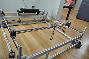
To develop a polymer laser welding system from scratch would have been extremely time-consuming and difficult, but to build on free and open-source designs is much faster and involves less effort. A group of my students including Rodrigo Periera Faria (from Brazil), Sai Ravi Chandra Parasaram (from India) and from the U.S. Nick Anzalone and Thad Waterman used Jansen’s design as a starting point to develop an open-source polymer welding system as shown in Figure 6.22.
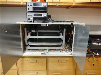
FIGURE 6.22 Open-source polymer welding system derived from open-source laser cutter in Figure 6.21.
The primary variations we made to Jansen’s system with dimensions of 1.5 ft by 1.5 ft included the following:
1. We mounted the whole system in a double drawer file cabinet (now that we all more or less only read academic papers on a screen, there are millions of filing cabinets available throughout the world’s universities) that we hollowed out, put on a safety switch for the laser, and new drawers with magnetic closers. A hole was drilled through the top for the wires and the fiber laser to pass through.
2. We extended the legs past a square bottom to allow for the cabinet rails to remain intact as seen in Figure 6.22.
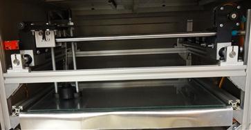
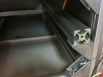
3. We added a second substrate layer that slides in consisting of a metal (Al) substrate and a lower iron glass cover plate (see details in Figure 6.23).
4. We added new 3-D printed parts which are available on Thingiverse38 to couple a fiber laser to the rig. In our case, it is hanging down just over the glass with a lens positioned so that the focal point is just under the glass.
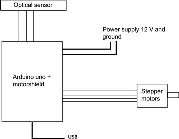
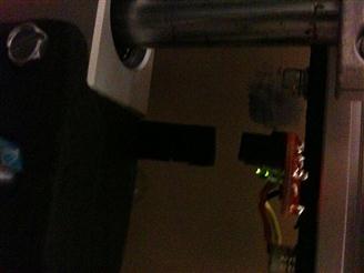
In addition to the printed parts, the system needs mechanical and electrical parts shown in Table 6.2. Finally, we used a fiber laser with full details available on Appropedia. It should be noted here that, like most open-source designs, this is a living, evolving research tool and any changes will be posted on Appropedia as we improve our design.39 To control the system, we used the electronic circuit schematic shown in Figure 6.24. The electronics build and communication setup has 10 easy steps:
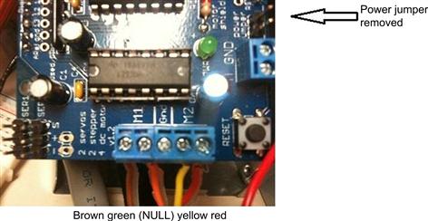
1. The jumper near to the GND pin must be removed; otherwise the Arduino will be damaged! (See details in Figure 6.25).
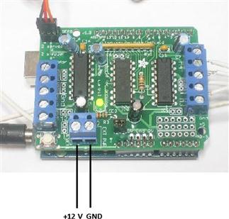
2. Connect the 12 V cable to M+ pin and ground to GND pin on the motor shield as seen in Figure 6.26.
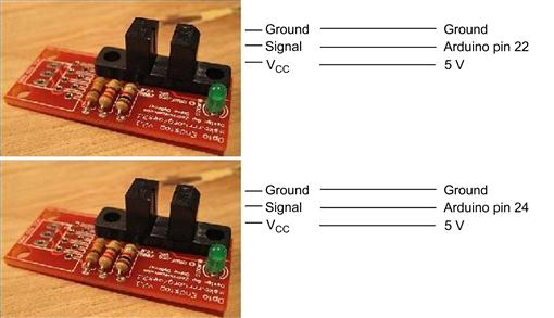
3. Connect the endstops as shown in Figure 6.27.
4. Fix the endstops such that the laser carriage reaches the lower left corner of the mechanism as shown in Figure 6.28.
5. For the following steps, use the chip and wiring pins outline in Figures 6.29–6.31. If using Adafruit stepper motors, connect the wires following the order: from M1 to M2, brown, green, skip Gnd pin, yellow and red. From M4 to M3, brown, green, skip Gnd pin, yellow and red.
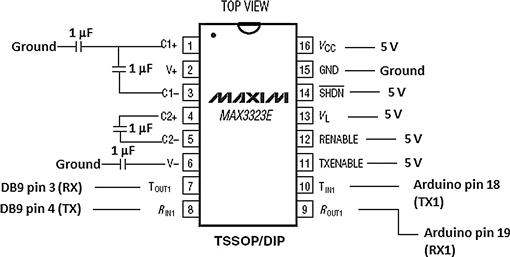
6. Connect MAX3323E pin 1 to a 1 μF capacitor, a 1 μF capacitor between 1 and 3, another between 4 and 5, and the last 1 μF capacitor to pin 6, as shown in the figure. Pins 7 and 8 go to the DB9 cable pins 3 and 4, pins 11, 12, 13, 14 and 16 to 5 V and pin 15 to ground. Pin 9 to Arduino pin 19 and pin 10 to Arduino pin 18. Ground the capacitors as shown, if using polarized capacitors, make sure to connect the negative sides to ground for the capacitors in MAX3323E pins 1 and 6, pin 3 for the capacitor between 1 and 3 and pin 5 for the capacitor between 4 and 5.
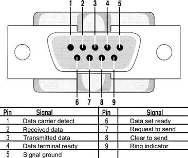
7. Connect DB9’s pins 1 to ground, pins 2 and 5 to pin 9, pin 3 to MAX3323 pin 7, pin 4 to MAX3323 pin 8, and pin 7 to pin 8.
8. Upload the firmware to Arduino using Arduino software.40
9. Connect the DB9 cable to LaserSource 4320 RS232 input.
10. For firmware, open-source software, and a template for this tool go here: https://sourceforge.net/projects/lasersystemforp/.
Table 6.2
Parts for the Open-Source Polymer Laser Welding System
| Misumi Part Description | Part Number |
| Precision linear shaft | PSFJ12-480 |
| Linear double bushings with pillow blocks | LHSSW12 |
| Linear single bushings with pillow blocks | LHSS12 |
| Aluminum extrusion four-side slots | HFS5-2020-2000 |
| Square nuts for aluminum extrusions | HNKK5-5 |
| Reversal brackets with tab | HBLFSN5 |
| Cap screws for aluminum extrusions | HCBST5-12 |
| T-shaped shaft supports | SHA1220 |
| Stock Drive Part Description | Part Number |
| 18 teeth polycarbonate timing pulley | A 6T16M018DF6005 |
| Fiberglass-reinforced neoprene toothed pulley belt | A 6Z16MB89060 |
| Electronic Parts | Source/Part Number |
| Arduino MEGA 2650 | Sparkfun 11061 |
| Adafruit Motorshield | Adafruit 81 |
| 2 × Adafruit stepper motor | Adafruit 324 |
| 2 × Opto endstop | Makerbot |
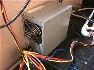
| Power supply 5 V and 12 V | (Used computer) |
| MAX3323 chip (or similar) | Digikey |
| 4 × 1 μF capacitors | Favorite electronic shop |
| Female serial-breadboard cable | Favorite electronic shop |
| Hookup wire | Favorite electronic shop |

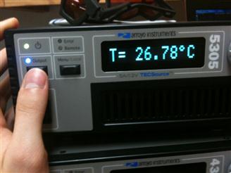
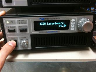
Next, set up the laser, which is composed of three main devices41: (1) LaserMount 264, (2) TECSource 5300 and (3) LaserSource 4320. The LaserMount 264 integrates a Peltier cooler for precise temperature control and the laser itself. TECSource 5300 is a temperature controller that needs to be attached with the LaserMount. LaserSource 4320 is a Laser Diode Driver; it controls the laser behavior such as voltage, current, pulse width modulator (PWM) duty cycles and on/off control.
Installation of the LaserSource and the TECSource are fairly straightforward. After unpacking the units, make sure all packing materials have been removed and nothing obscures the ventilation ports on the side and front of the units. Change the voltage selection to the appropriate value and make sure both devices are properly grounded. The devices have vent holes on the side and front; do not block these vent holes, or overheating may occur, causing damage to the unit. Connect the cables from the TECSource- and the LaserSource-labeled LASER and TEC to the LaserMount properly. To power up the unit, connect the AC power cord to the unit, turn the power switch, located on the front panel, to the on (I) position. The unit will display the model, serial number, and firmware version, go through a quick power-up self-test, and return to the last-known operating state. In order to achieve the highest level of accuracy, the TECSource should be powered on for at least 1 h prior to taking measurements. Once devices are powered up, it is necessary to enable the External Fan Control on the TECSource menu options. Make sure the temperature controller current limit is set to a maximum value of 7.4 A.
As with all lasers, you need to take proper safety precautions with this setup. Below are some general guidelines, but you should contact the manufacturer and your institution’s safety personnel before you build or operate this system. At your institution, there are probably rules governing laser safety in detail. At our institution, the LSO needs to be notified of the purchase of any laser, regardless of the class. Such notification should include the classification, media, output power or pulse energy, wavelength, repetition rate (if applicable), special attachments (frequency doublers, etc.), beam size at the laser aperture, beam divergence and users. We overcame the requirement to keep the laser in a shielded room by putting in a box with a safety switch, which does not allow the laser to turn on if the doors are open. To make this effective, follow this primary rule: when operating the laser, make sure that the doors to the rig are closed and that you are wearing laser safety glasses.
No attempt should be made to place any shiny or glossy object into the laser beam other than that for which the equipment is specifically designed. Eye protection devices which are designed for protection against radiation from a specific laser system should be used when engineering controls are inadequate to eliminate the possibility of potentially hazardous eye exposure (i.e. whenever levels of accessible emission exceed the appropriate MPE levels). This generally applies only to Class IIIB and Class IV lasers. All laser-protective eyewear should be clearly labeled with optical density values and wavelengths for which protection is afforded.
Skin protection can best be achieved through engineering controls. If the potential exists for damaging skin exposure, particularly for ultraviolet lasers (200–400 nm), then skin covers and or “sun screen” creams are recommended. Most gloves will provide some protection against laser radiation. Tightly woven fabrics and opaque gloves provide the best protection. A laboratory jacket or coat can provide protection for the arms. For Class IV lasers, consideration should be given to flame-resistant materials.
The software for this system is all free and open source and includes the following:
1. Hydra—MMM modified for the Laser Welder.42 Java JRE required.
2. Processing43—if using source code.
3. Inkscape44—for making new laser path designs. You will also need the GCodeTools for Inkscape.45 To install the Gcode tools in Linux unpack and copy all the files to the following directory, /usr/share/inkscape/extensions/ and restart Inkscape.
4. You can also get the template file from Appropedia.46
To load a sample for a welding experiment, follow these steps:
2. Carefully remove the aluminum + glass slider as shown in Figure 6.32.
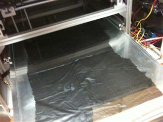
4. Place the plastic layers (two the first time and adding one per weld routine if more than two).
5. Stretch the plastic layers flat/cold weld with rolling pin and make sure that they are touching each other with as few wrinkles as possible. Alternatively, you can pin them down over the edges.
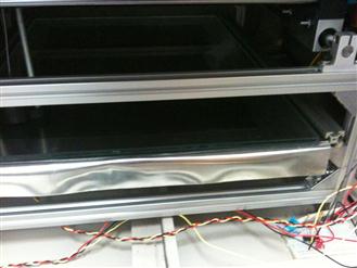
7. Slide the arrangement back to the box carefully to not break the laser mount (see details in Figures 6.33 and 6.34).
8. When the substrate is mounted properly as seen in Figure 6.35, close the box and put on the safety glasses.
Next, to power up the open-source laser welder and the associated communications, do the following:
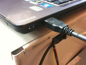
1. Disconnect USB cable as shown in Figure 6.36.
2. Turn on the power supply shown in Figure 6.37 (Do not connect the USB cable before this!).
4. Turn on TECSource 5305 (shown in Figure 6.38), wait until it boots, and then press Output.
5. Wait until it stabilizes at the temperature set point (currently 25°C).
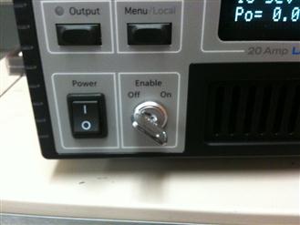
6. Turn on 4320 LaserSource as shown in Figure 6.39.
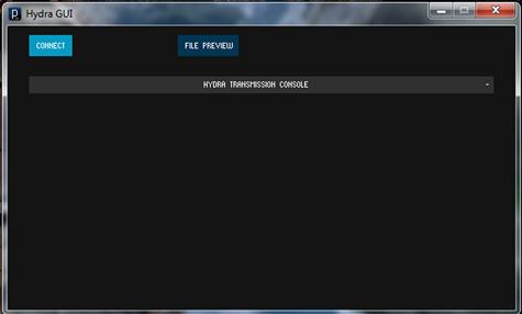
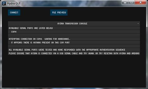
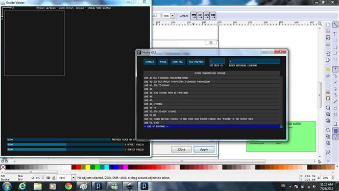
7. Open the Hydra GUI and click on “connect” as shown in the screenshot in Figure 6.40.
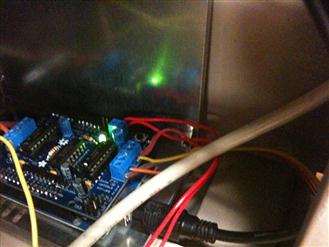
8. If you receive this error message (e.g. Figure 6.41), restart the program and reset the Arduino (Figure 6.42), and then click on “connect” again.
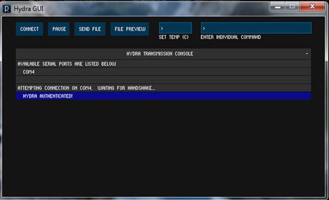
9. Connected (Figure 6.43) and ready for use!
Next, you will want to make a design to weld. This is done by drawing the design in Inkscape and exporting GCode (similar to the slicing that takes place for the RepRap in order to tell the tool head where to go). The process is as follows:
1. After installing Inkscape and GCodeTools following the instructions above, run Inkscape.
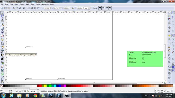
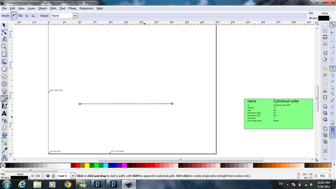
2. Open the file TEMPLATE.svg as shown in Figure 6.44. The template has the working area limits and other things necessary to generate the GCode correctly for this specific design of open-source welding rig.
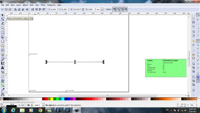
3. Draw a line, as shown in Figure 6.45, by selecting the line and press Ctrl + Shift + C, as shown in Figure 6.46. In the same way, you can build up much more complicated designs.
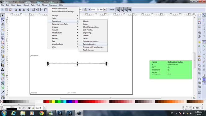
4. Go to Extensions >> Gcodetools >> Path to Gcode (as shown in Figure 6.47).
5. On the tab Preferences, type the File name (with .gcode in the end) and the directory you want to save it in.
6. Go to Path to GCode tab and Apply. The GCode should now be generated to the directory folder.
Now, you are finally ready to weld!
1. Close the box and put on the safety glasses.
2. Turn the LaserSource enable key to On (Figure 6.48).
3. In Hydra, click on Send File, select the GCode file and click open again (Figure 6.49).
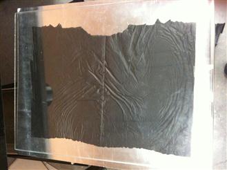
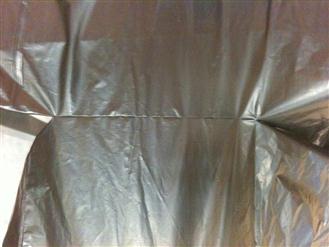
Now be amazed at your perfect polymer weld as shown in Figure 6.50.47
For full operations and any changes/improvements and new versions, see the MOST protocol page.48 Designing the open-source laser welder in this way and sharing everything associated with it not only makes it easy for future students in our group, like Brennan Tymrak, to start large-scale prototyping and testing of expanded microchannel polymer heat exchangers, but it also makes it easy for others to build on our technologies. The benefits of this sharing approach for an academic are well known, as discussed in Chapter 2.
6.3.2 Radiation detection with open-source Geiger counters
There are many scientists and engineers that work with radioactive materials and may find it useful to have a low-cost, reliable, open-source radiation detector. In addition, many “citizen scientists” may be interested in obtaining reliable first-hand information about dangers near a nuclear power plant accident or other forms of radioactive release.
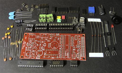
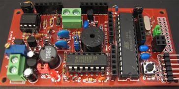
There are several OSH Geiger counters available. For example, the design of the Libelium Team’s board,49 which is a shield for the Arduino (discussed in Chapter 4), is open hardware and the source code is released under GPL (discussed in Chapter 2). In addition, there is an open Geiger counter circuit50 that interfaces with an Arduino and a project kit to build it is available.51 The Geiger Kit provides the electronics as shown in Figure 6.51 (and assembled in Figure 6.52) needed to run and detect events from a GM tube.
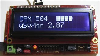
The events are counted and displayed as counts per minute and microSievert per hour (μSv/h) as shown in Figure 6.53 by an ATmega328P microprocessor running preloaded software. The data can be output to a computer via a serial connection.
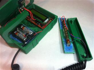
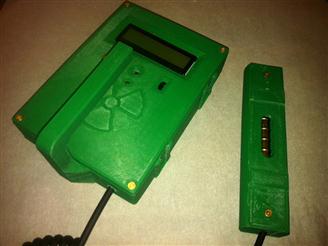
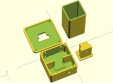
With the use of a 3-D printer as discussed in the last chapter, you can even print a case with a detachable probe to house your Geiger counter with a design by Stephen Bailey, shown as designed in Figure 6.54 and fully assembled in Figure 6.55.52
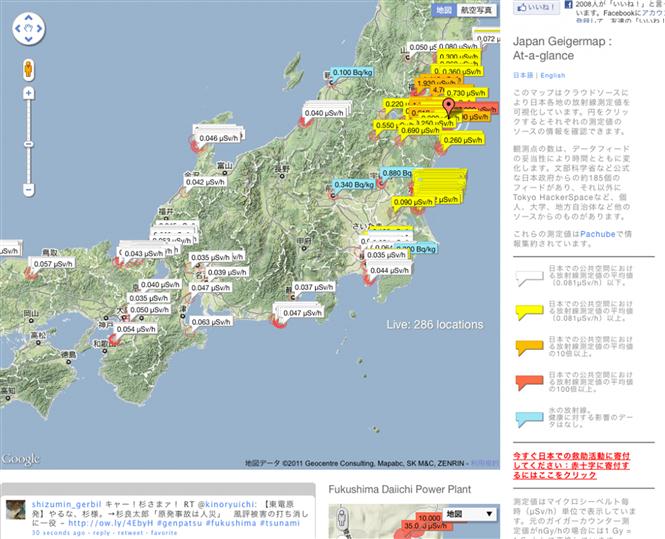
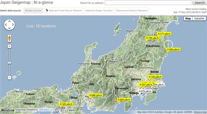
For such projects, a major impetus was to help people in Japan to measure the levels of radiation in their everyday lives after the unfortunate earthquake and tsunami struck in March 2011 and caused nuclear radiation leakages in Fukushima. Due largely to conflicts of interest, the official announcements of nuclear accidents are viewed as unreliable by much of the public.53 For example, during the Fukushima disaster, the Japanese public found official reports extremely dubious and government officials appeared to be actively preventing citizens from obtaining data [29]. Even in the United States, our government appeared reluctant to post online whatever radiation levels they were monitoring as radiation from Fukushima hit the West Coast, and there were several reports that their monitors crashed [30]. A response from citizen scientists in Japan was to crowd-source radiation Geiger counter readings from across their country using a collection of both OSH and open-source software [31] as can be seen in the Japan Geigermap: at-a-glance both then (Figure 6.56) and now (Figure 6.57).
This kind of activity may be the start of a movement to bring more people into science and act as a check on bad or dishonest sources of scientific information for the public [32]. Conceptually, this type of crowd sourcing of scientific data is considered as part of the “Participatory Sensing” framework, whereby ad-hoc sensor networks are formed, taking advantage of sensors (possibly embedded in mobile devices54) to enable public and professional users to gather, analyze and share geographically localized information [33]. Scientists have already concluded from the many crowd-sourced experiments completed that individuals can act as sensors to give useful results in a timely manner and can complement other sources of data to enhance our situational awareness and improve our understanding and responses to such events [34].
6.3.3 Xoscillo—an open-source oscilloscope
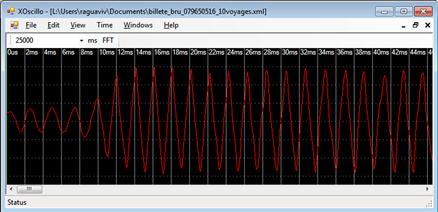
As you are building your OSH for other projects, you may need to debug an electronic circuit. Although a simple multimeter is an indispensable tool for doing this, as your projects become more complex, you may need a more sophisticated tool to understand what is going on in the circuit in the form of wave forms. This calls for an oscilloscope. The least expensive commercially available oscilloscopes cost around a few hundred dollars. What if you could have functional oscilloscope using only the inexpensive Arduino board you already have? You are in luck. Xoscillo55 is an inexpensive, open-source software oscilloscope that acquires data using an open-source Arduino microcontroller board (discussed in Chapter 4) or a Parallax USB oscilloscope. It has been released under CC-BY-NC-SA. The Xoscillo does not have all of the functionality of the high-end oscilloscopes, but it may meet many of your needs. There is no need for extra hardware to get the basic functionality, but the maximum frequency is 7 kHz. You can obtain up to four channels, but this lowers your sample rate (7/4 = 1.75 kHz). It has 8-bit vertical resolution, variable trigger voltage on channel 0, and can sample data indefinitely.
The hardware of the simplest embodiment of the Xoscillo is just an Arduino board with its analog inputs connected to the output of the circuit where the waveform is that needs to be observed. This setup is connected to a PC, and the inputs read by the Arduino are analyzed and shown on the screen of the PC.
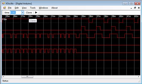
To get started, flash your Arduino with the firmware that comes in the zip file at the link above. Use the analog inputs from #0 to #3 on your board. Launch the application and in the menu, go to “File” and then click on “Arduino”. A basic screenshot showing the Xoscillo displaying a simple waveform and a logic analyzer is shown in Figures 6.58 and 6.59, respectively.
6.4 Environmental Science: Open-Source Colorimeters and pH Meters
OSH can also be used for environmental science. In this section, we will look at designs for an Arduino-based colorimeter and pH meter. After detailing the design and fabrication of the devices, the quality is discussed to provide data for conclusions about future development of other open-source analytical tools discussed in Chapter 7.
6.4.1 Open-source colorimeter
Colorimetry is a scientific technique that is used to determine the concentration of colored compounds in solutions by the application of the Beer–Lambert law, which states that the concentration of a solute is proportional to the absorbance. To do colorimetry, you need a colorimeter, which starts in the hundreds of dollars for a lab-grade tool. In general, a colorimeter is used to measure the absorbance of only a particular color (e.g. wavelength) of light for a specific solution. A colorimeter is a relatively simple scientific device consisting of a light source, sample holder (normally a cuvette or test tube), light intensity sensor and means of controlling the light source and integrating transmitted light intensity. Incident light is generally filtered allowing only a narrow band of wavelengths near the absorbance peak for a given dissolved species. The method requires a blank solution for calibration (zero) and reports results in absorbance units, transmittance or if it is calibrated, it can apply the Beer–Lambert law to report results as a concentration [35]. Colorimetric methods are used widely in research and in many industries, including investigating the food we eat—such as during storage of bread [36], chocolate [37] and milk [38]. For example, in environmental science, colorimeters are used to monitor the levels of nitrates, phosphates, metals and other compounds present in effluent entering the natural environment from the manufacturing of paper and other commercial goods [39,40]. They have also traditionally been used to estimate the population density of protozoa in a culture, and more recently by the medical community, to measure the UV radiation exposure of children though skin color changes and to study the aging of bruises [41–43]. One of the more popular applications of a colorimeter is measuring the chemical oxygen demand (COD) for estimating the organic content of wastewaters. This is particularly important for some areas of environmental science. COD is also a measure included in some water quality indices [44]. There are sophisticated and expensive methods to determine COD with high accuracy [45,46], but often at high cost and increased production of waste from the analyses.
This section provides a design and technical validation of an open-source colorimeter [47] using the closed reflux COD method (EPA method 5220D). This approach is evaluated for its potential to reduce the cost of equipment to perform colorimetric COD.
The open-source colorimeter case design was wholly completed in OpenSCAD following the techniques outlined in Section 6.1.1. The design of the case body is shown schematically in Figure 6.60 and is available on Thingiverse56 and is discussed in detail including bill of materials (BOM) and firmware on Appropedia.57 The assembled case with electronics is shown in Figure 6.61.
The case was printed with black polylactic acid (PLA) media with three outer layers so as to minimize stray light inside the detection area. An open-source RepRap 3-D printer following the design outlined in Chapter 5 can be used to produce the print after slicing the OpenSCAD-produced STL model with the open-source slicing software such as Slic3r or Cura.
The electronics are based upon the open-source Arduino prototyping platform discussed in Chapter 4, which exposes the digital and analog I/O as well as processing capabilities of an Atmel Atmega microprocessor in a single convenient package. The platform encapsulates the hardware required to interface the Arduino with a host computer and includes a custom bootloader that executes compiled C++ code that can be developed in the Arduino integrated development environment (IDE). As we discussed, the Arduino platform is designed to use customized electronic boards (shields) that can be conveniently pressed into place and that typically come with software libraries so as to facilitate integration of board features into the custom code developed by the end user. A display shield incorporating a 16 × 2 character alphanumeric liquid crystal display (LCD) and D-pad button interface is used to navigate and select device functions and display the results of analysis. The shield is also OSH, supplied by Adafruit Industries,58 a company dedicated to developing and providing low-cost, innovative and useful open-source electronic solutions. A single 5 mm through-hole LED having an emission peak near 606 nm was used as a light source (this of course can be exchanged for an LED of another wavelength for your specific application). A Taos TSL230R light intensity-to-frequency sensor was employed to measure incident light intensity. A total of only three discrete electronic components are required for the circuit, as shown schematically in Figure 6.62.
The schematic was developed at Fritzing.org,59 which is extremely useful for sharing your electronic design schematics. It is clear from Figure 6.62 that the design does not come close to need the full functionality of even the Arduino Uno and thus could be made even more inexpensively. This is left for future researchers working on specialized projects because again using the Arduino greatly accelerates the ability of the user to get a functioning device in a short amount of time for a wide range of applications. The open-source colorimeter’s firmware was developed with the Arduino IDE by G. Anzalone and provides an easy-to-navigate hierarchical menu system for selection of the device’s functions.
Colorimetric methods are used to determine the concentration of dissolved species, relying on the ability of many ionic species to absorb light of one or more specific wavelengths, followingthe Beer–Lambert law shown in Eqn (6.1):
 (6.1)
(6.1)
where A is the absorbance (absorbance units), I is the intensity of light passing through unknown, and I0 is the intensity of light passing through the blank. The absorbance is related to concentration as shown in Eqn (6.2):
 (6.2)
(6.2)
where aλ is the molar absorptivity of the species of interest at a certain wavelength (λ) of light, b is the path length of light through solution, and c is the concentration of the analyte.
The design was evaluated using the closed reflux COD method [47]. The closed reflux colorimetric method used for COD employs potassium dichromate (K2Cr2O7) as oxidant, requires only a small sample size, and produces minimal waste. A 2 ml aliquot is added to dichromate solution and allowed to digest at 150 °C for 2 h. Concentration (mg COD/l) is determined by measuring the increase in absorbance at 606 nm, the absorbance peak for the chromic ion, or determining excess dichromate by measuring the absorbance at 440 nm [48,49].
High-range COD digestion vials from Hach Company were used to digest samples produced during unrelated research activities conducted to develop precision and bias statements for a newly developed analytical procedure. In a study [47] comparing the open-source colorimeter and a commercial Hach DR890 portable colorimeter, the open-source colorimeter results (2 mg COD/l) were well within the stated precision of 17 mg COD/l of the Hach method [50]. This indicates that it is suitable for use in any of the standard COD applications.
As usual, the OSH alternative is considerably less costly than closed commercial versions. The open-source colorimeter can be built for one-tenth of the price (approximately US$50) of the least expensive, commercial COD-only instrument available and two orders of magnitude less than the Hach DR890 that it was compared to in this evaluation. Both the hardware design and software are now freely available online and under the creative commons CC-BY-SA license (see Chapter 2 for more details) such that they can be modified and new designs derived. To put this work in further perspective, for about the cost of a standard commercial COD instrument, a research lab can purchase an open-source 3-D printer (or the parts for several—as we saw in Chapter 5) and all the parts to make the open-source colorimeter described here. Thus, perhaps most importantly, the ease and low cost of this approach for developing sensor-based tools enables increasingly sophisticated tools to be used in low-funded developing world laboratories, helping to disseminate open-source appropriate technology for sustainable development [20,51–53]. In addition, high-quality, open-source scientific hardware, such as the colorimeter described here, provides public, nonprofit and nongovernmental institutions, schools and amateur scientists the tools necessary to conduct real science, while driving down the costs of research tools at our most prestigious corporate, government, and academic laboratories [2].
6.4.2 Open-source pH meter
The measure of pH is a measure of the hydrogen ion concentration—or a method to measure the acidity or alkalinity of a solution. By definition, aqueous solutions at 25 °C with a pH less than seven are acidic, while those with a pH greater than seven are basic or alkaline. A pH level of 7.0 at 25 °C is defined as “neutral” because the concentration of H3O+ equals the concentration of OH− in pure water (H2O). A pH meter is an electronic device used for measuring the pH of a liquid. A typical pH meter consists of a measuring probe (a glass electrode, which is a type of ion-selective electrode made of a doped glass membrane that is sensitive to a specific ion) connected to an electronic meter that measures and displays the pH reading. pH measurements are important in a long list of applications including environmental science (e.g. environmental monitoring of soils, water of rivers, lakes, and rain), medicine, biology, chemistry, agriculture, aquaculture, forestry, food science, oceanography, civil engineering (e.g. monitoring of sewage treatment tanks), chemical engineering, nutrition, water treatment and water purification, and many other applications. It is a useful and fundamental property needed in dozens of fields.
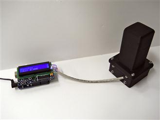
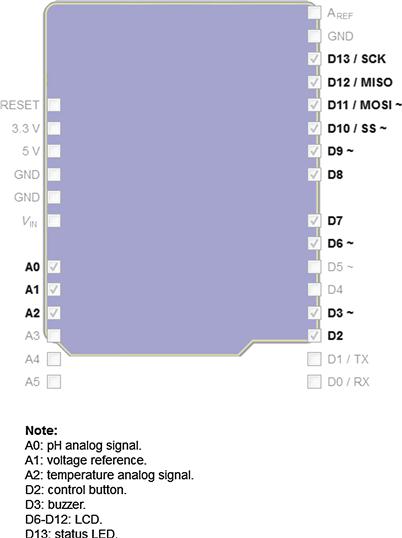
The open-source pH meter discussed in this section was developed by Carlos Neves, a Brazilian scientist with a dedication to OSH.60 The open-source pH meter is a glass electrode pH meter using the Arduino microcontroller detailed in Chapter 4 and is thus compatible with the Freeduino.61 Full details (hardware, software, operation manual, etc.) can be downloaded for free62 with the code under a GNU GPL v2 and the content under CC-BY-SA 3.0.
Similar to the open-source environmental chamber in Chapter 4 and the open-source colorimeter in the previous section, the pHduino operates as a stand-alone unit using an LCD to display the pH and the temperature data like any commercial pH meter. Again, similarly, you can control it using a computer by USB port in addition to loading up the firmware. For this design, the signal gain (slope) and the signal offset are adjusted manually by trimpots and the signal is compensated by a temperature sensor. Unlike other examples in this book, this particular design can be more expensive than the low-end commercial pH meter bench instruments that are mass produced due to the tool’s vast collection of applications. However, the pHduino has significant advantages, which provide it with superior value. It is interfaceable, programmable, expandable, and, of course open and free, so you are free to adapt it to your specific application without paying additional money to a vendor. As it develops and matures, similar to other areas of complex open-source scientific tools, making and, specifically, printing it from functional materials should reduce costs below those that can be manufactured conventionally and sold.
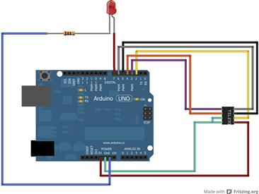
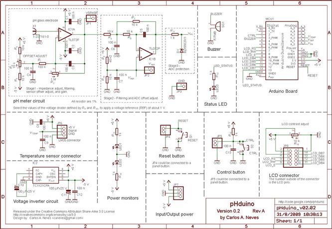
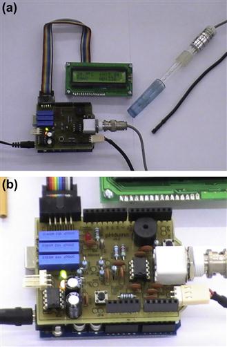
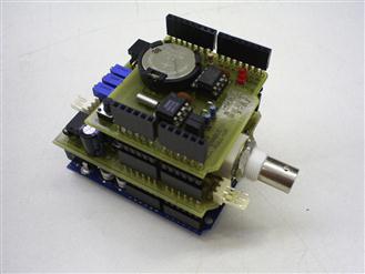
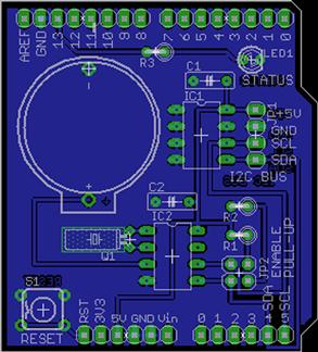
The printed circuit board (PCB) layout is shown in Figure 6.63, the electronic schematic is shown in Figure 6.64, and the Arduino shield details are shown in Figure 6.65. The completed pHduino is shown in Figure 6.66(a) with details in Figure 6.66(b).
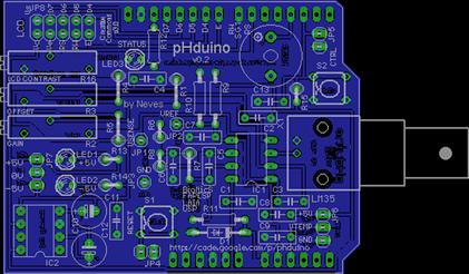
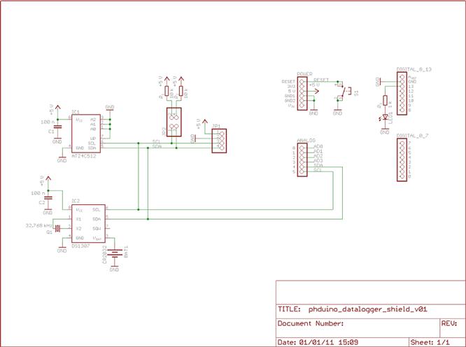
In addition, the pHduino can be improved with the addition of an open-source (hardware and software) pHduino Datalogger63 shown in Figure 6.67. The datalogger is a shield using an I2C real-time clock (RTC) and an I2C EEPROM memory. The circuit is relatively simple as can be seen in the PCB layout for the datalogger in Figure 6.68 and the electronic schematic shown in Figure 6.69. Users can mount the datalogger using a breadboard or a universal prototyping board. The datalogger is functional, but somewhat limited as the AT24C512 I2C EEPROM (512 kB) is not a large amount of memory, although it is inexpensive and easy to use. The DS1307 I2C real-time clock is a standard RTC for microcontrollers. Finally, a CR2032 battery is used to retain the parameters. For full build instructions and details, see Carlos’ detailed and updated web pages.
You are encouraged to build on these open designs and improve the resolution of this instrument to compete with the most expensive and sophisticated commercial pH meters. The pHduino was designed to be a simple, easy to understand, and easy to modify analytical tool like the open-source spectrometers to be discussed in Section 6.6. Like the open-source colorimeter, the pHduino could also be immediately improved to be a field instrument (beyond a bench top!) by providing a case for it similar to the Geiger counter in the previous section. Again, we are at the beginning and just scratching the surface of open-source scientific hardware. You should expect more sophisticated high-performance tools to be on the Internet shortly—may be you can help accelerate their development?
6.5 Biology: OpenPCR, Open-Source Centrifuges and More
OSH can also be used for biology, biological science, and bioengineering. In this section, we will look at designs for an open-source polymerase chain reaction (PCR) machine, open-source centrifuges, and many other biological research tools. The results of the equipment from the designs are discussed similarly to the last section to provide data for conclusions about future development of other open-source analytical tools discussed in Chapter 7.
6.5.1 OpenPCR
PCR is a biochemical technology used in molecular biology research to amplify a relative handful of copies of a piece of DNA (or even a single piece) by making as many as you like (e.g. thousands to millions of copies). The replications of a particular DNA sequence is useful for literally dozens of applications in biology and medical science, which include (1) DNA cloning for sequencing; (2) DNA-based phylogeny, or functional analysis of genes and analyzing gene expression levels; (3) the detection and diagnosis of infectious diseases including both viral and bacterial infections (thus it is also useful for doing water quality testing or food safety testing); (4) diagnosis of hereditary diseases; and (5) the identification of genetic fingerprints, which is useful in forensic science. For all its utility, the PCR method is actually fairly simple; it uses cycles of repeated heating and cooling (e.g. thermal cycling) of the reaction for DNA melting and enzymatic replication of the DNA. Short DNA fragments called primers, which contain sequences complementary to the target region along with a DNA polymerase, enable selective and repeated amplification. A chain reaction is established where the DNA template is exponentially amplified because the DNA generated is itself used as a template for further replication. The more you have, the more you get and the faster you can make the next batch. The method is extremely effective, although the commercial equipment is staggeringly expensive, and this has set up a large and ugly intellectual property battle. The IP battle continues to this day, despite the fact that the original PCR and Taq polymerase patents expired in 2005. For more details on negative effects of intellectual property on scientific progress and innovation, see Chapter 3. The answer to the unnecessarily complicated world of intellectual property when it comes to science is, of course, to develop open-source PCR equipment.
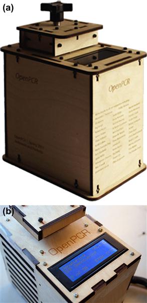
Fortunately, this has already been accomplished as you can see in Figures 6.70(a) and (b), which show the OpenPCR in action. OpenPCR is a low-cost, yet accurate, thermocycler you build yourself, capable of reliably controlling PCR reactions for DNA detection, sequencing and other applications.64 You can buy the OpenPCR kit for $600 and build it in about 3 h using only a Phillips head screwdriver, a 2 mm flathead screwdriver and a pair of pliers. The assembly is reminiscent of the old laser-cut wood 3-D printers—only much easier and less time-consuming to assemble. OpenPCR also utilizes the Arduino platform as described in detail in Chapter 4. The OpenPCR is completely open source including the Arduino software,65 CAD files,66 the PCB design,67 and the BOM.68
The OpenPCR has a sample capacity of 16 0.2 ml tubes. It can operate at temperatures from 10 to 100 °C (±0.5 °C). The average ramp rate is quite fast and is about a degree per second. The heat block for the OpenPCR is currently machined out of a highly thermally conductive alloy of aluminum, until 3-D printing of metals becomes common.69 The block is insulated at the sides to ensure a uniform temperature across the block and tight contact with standardized 200 μl PCR tubes. This results in a temperature which is uniform within ±0.3 °C. The OpenPCR is completely programmable/automatable—so you can set up the initial, cyclic and final steps from either a connected computer or after it has been set up to run as a stand-alone unit. One of the primary features of the OpenPCR is the heated lid that can range from the ambient temperature in your lab up to 120 °C. The heated lid heats up the tops of your tubes and ensures that condensation is prevented, thereby improving your results by ensuring that your reagent concentrations remain correct throughout the cyclical process—just as high-end PCRs do. If this was a closed, commercialized PCR and you were unhappy with the features, you could call and complain to the company, go shopping again, or start from scratch and build one yourself. That is not a very good range of options. However, as with all OSH tools, with the OpenPCR, you can change or enhance it to meet your specific needs—the “activation energy” to build on the already created open design is much less than that to start from scratch. OpenPCR has already been hacked to do microfluidic PCR, and software has been written for complete laboratory automation.
6.5.2 Open-source centrifuges
A laboratory centrifuge is used to spin liquid samples at high speeds and has many applications in a range of different types of biological laboratories. Centrifuges work using the sedimentation principle, where the centripetal acceleration causes denser substances to separate out along the radial direction (e.g. for particles to collect at the bottom of the tube). There are many types of centrifugation, which are useful in the laboratory including (1) differential centrifugation, which can separate certain organelles from whole cells for further analysis of specific parts of cells; (2) isopycnic centrifugation, which is used to isolate nucleic acids such as DNA; and (3) sucrose gradient centrifugation, which is used to separate cell organelles from crude cellular extracts and to purify enveloped viruses and ribosomes. Microcentrifuges tend to be the most useful in a lab as they are designed for small tubes able to hold from 0.2 to 2.0 ml (micro tubes). In general, these small devices can obtain up to 30,000 g (where g is the acceleration due to gravity at the Earth’s surface). Protocols for centrifugation normally specify the amount of acceleration to be applied to the sample, rather than specifying a rotational speed such as revolutions per minute (RPM), which is useful because it enables protocols to span different devices with various rotor lengths. The relative centrifugal force [g] applied to a sample in a centrifuge is given by Eqn (6.3):
 (6.3)
(6.3)
where r is the rotational radius in centimeter and s is the rotational speed in RPM. Here, we will briefly outline several types of open-source centrifuges.
6.5.2.1 DremelFuge
Of all the open-source centrifuge designs, the DremelFuge is perhaps the most elegant. The DremelFuge (as shown in Figure 6.71) is a printable rotor for centrifuging standard microcentrifuge tubes and miniprep columns, which uses a high-speed drill or Dremel tool to spin down samples as shown in Figure 6.72.70 The Dremelfuge was developed by Cathal Garvey in Ireland to assist in his research with DIYbio.71
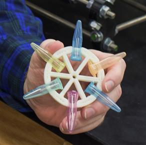
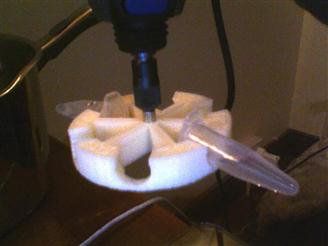
The primary idea behind the DremelFuge is that it can be used in the field as an extremely inexpensive centrifuge (costing about $50—primarily the cost of the drill—compared to commercial systems starting over $500). It can be used for any application in development needing a microcentrifuge including medical, biochemistry or education in the sciences. It uses industry standard 1.5 ml/2 ml Eppendorf/Microcentrifuge tubes.
The applications of the Dremelfuge are numerous and impressive. For example, when used with a drill at 3000 RPM, the Dremelfuge will deliver over 400 g, enough to comfortably spin down Miniprep samples. When used at 10,000 RPM, on a rotary tool for instance, a Dremelfuge should deliver over 4,400 g, more than enough to spin down bacterial cells. The Dremelfuge has surprisingly competitive technical specifications, when used on high-speed Dremels. For example, at 16,000 RPM, Dremelfuge matches commercial centrifuges. It can do better. If a Dremelfuge is used with a Dremel 300, a maximum speed of 33,000 RPM equates to a force of over 50,000 times earth’s gravity, which puts it into so-called “Ultracentrifuge” territory. The latest version (as printed by Shapeways72) has successfully spun tubes at this speed.
Obviously, the Dremelfuge is a potentially hazardous tool and significant safety considerations and common sense are necessary when using it.73
The general steps for making and using a Dremelfuge are the following:
1. Print the Dremelfuge chuck on a RepRap or buy Dremelfuge preprinted from a 3-D printer supplier. When printing, use the maximum infill for strength and stability.
2. Attach the Dremelfuge chuck securely, either by tightening a chuck securely or screwing a rotary tool disc holder securely to the center of the Dremelfuge.
3. Seat your drill or rotary tool so that Dremelfuge’s shaft/axle is vertically oriented. You can do this using conventional building materials, OpenBeam (as was discussed in the beginning of this Chapter) or Makerbeam, or even conventional chemistry setups. Then, place the drill/tool with the Dremelfuge into a metal chamber (e.g. a metal cooking pot) for safety. Wear eye gear and other appropriate personal protective items to protect yourself in case of disintegration.
4. Start at the lowest speed and ramp up the RPMs. Do this first with no tubes or loads attached and test the Dremelfuge for safety at the speeds you intend to use it.
5. Once proven safe at the intended speed, you can start to test and use Dremelfuge under load, that is with desired size of the lab samples and perhaps water. Once this is done, move to the lab samples. Make certain at all times that identical tubes or columns are used, with identical amounts of fluid or mass on either side to maintain balance. Always balance the Dremelfuge or accidents may result.
6.5.2.2 Microcentrifuge
If you are willing to trade a little performance for a very low-cost centrifuge, consider the table-top microcentrifuge74 (shown in Figure 6.73) developed and open-sourced by Thingiverse user Tinytim.
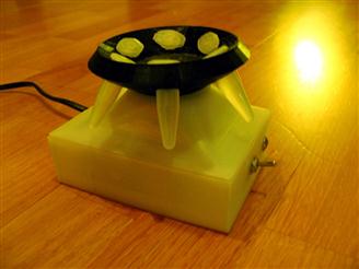
The BOM includes the following:
1 × Graupner speed 400 motor (or similar sized motor, available on the Internet or your local model shop)
1 × 220 V to 6 V trafo (Shown: a small print-trafo 6 V, 3.2 VA, size 35 × 42 × 30 mm)
1 × pot suitable to regulate your motor speed (the size depends on your motor’s Ohm)
2 × 3 mm screws (about 5 mm long)
2 × 3 mm threaded rod (about 1 cm long), with a slit sawed into it as an inexpensive replacement for a headless screw
Printed parts (printed in PLA, 1.2 mm wall-size, 50% infill for all parts—0.2 mm slicing using Cura).
Print your parts on a RepRap (built in the last chapter) or similar. Both the rotor and casing bottom can be printed without support material; however, the casing top does demand support printing.75 Next, wire and assemble. For your first test, it is recommended that you take it up to speed inside a steel pot, similar to the protocol for the DremelFuge. Afterwards it can function as a desktop centrifuge. If you are concerned about safety or your own making skills, you can build or print a safety shield for it as shown in the next example. The example shown here can spin up to 16,400 RPM at 7.2 V, but was only run at 6 V. Again, be careful particularly with the printing as a rotor that is not printed carefully may break during centrifugation and cause damage or injury.
6.5.2.3 USB powered cytocentrifuge
The third type of previously designed centrifuge is the USB powered cytocentrifuge76 developed by Thingiverse user siderits (Dr Richard Siderits of Robert Wood Johnson University Medical School) for under $10. It uses a small DC motor (1.5–6 V, 4000 RPM) and a DC motor speed controller kit to create the USB powered biocentrifuge shown in Figure 6.74. Although you can use longer rotor arms, the test centrifuge has a radius of 40 mm. The motor will spin up to 4000 RPM on 4.5 V/100 mA USB port power giving a centrifugal force of 500 g. The USB centrifuge can be placed in either a printable enclosure or any other appropriate enclosure to make a functional very inexpensive low-end centrifuge.
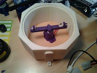
To fabricate the USB centrifuge, print out the parts, purchase an appropriate DC motor, the speed controller and assemble. Similar to the Dremelfuge, the printed parts that experience physical forces should be printed at 100% fill. In the example shown, the US$8 DC motor speed control PWM is part number FK804 from Bakatronics. The potentiometer controls the width of the pulses to control the speed of the motor. It can be mounted directly on the unit, remotely on a control panel or in a printed enclosure, or in FB enclosure to make a hand-held throttle. The USB centrifuge uses a 12C power supply, but can be used as low as five VDC. The housing is FB03 and the PCB is 1.8″ × 1.3″. The maximum current is 1.5 A. In addition, you can add a DPDT slide switch for reversing the direction of the motor. If you do not have a small DC motor that has speed up to 4000–5000 at 1.5–6 V, you can salvage, you can buy one for about $3 from numerous Internet vendors. Lastly you will need an old USB cable.
Dr Richard Siderits is an excellent example of the open-source scientist of the future. He is an Anatomic and Clinical Pathologist, fellowship trained in Experimental Pathology and he is currently an Associate Professor at Robert Wood Johnson University Medical School, Department of Pathology and Laboratory Science. In addition to his research, he especially enjoys teaching rapid prototyping and science, technology, engineering and mathematics (STEM) principles (including, of course, 3-D Printing) as they apply to the medical sciences and the history of medicine. The shear volume of his contributions to open-source science is already substantial. For a full list, see his Thingiverse user page.77 In addition to the cytocentrifuge, he has shared designs for many useful tools such as 3-D printable rapid fluid filters78 as seen in Figure 6.75, PCR tube racks79 (Figure 6.76), cassette racks80 (used to organize cassettes that hold tissue samples and large specimens in surgical pathology and shown in Figure 6.77), and platypus forceps81 (Figure 6.78), which hold a portion of tissue so that a scalpel or microtome blade can slide in between and section the tissue at a uniform thickness.
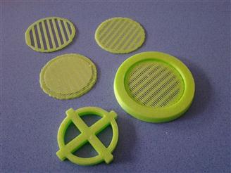
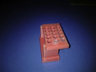
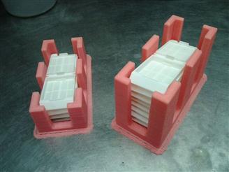
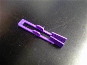
Currently, he is working on several projects that should be coming out as this book is printed, including a home bioprinter made using Makerbeam82 connectors (which he has already developed as seen in Figure 6.7983) and stepper motors, an auto slide stainer for histology (two-slide version), an auto immunohistochemical stainer (single-slide version) and a USB-powered real-time quantitative PCR module. Finally, if you want to see how science used to be done or want to better explain it to your students, he is developing a line of working 3-D printed reproductions of vintage laboratory equipment circa 1850–1920.
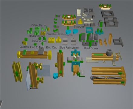
6.5.3 Other useful open-source biological research tools
There are many other useful open-source biological research tools already available and this book does not even attempt to catalog all of them, but I would like to pique your interest in using and sharing OSH, so consider the following simple examples of tools that can save your biolaboratory money.
Racks for vials and test tubes proliferate on the open-source scientific hardware community. For example, you can get test tube racks that are made with laser cutters84 as designed by Thingiverse user Eithen and shown in Figure 6.80 or with 3-D printers85 as designed by Thingiverse user _Kid_ as shown in Figure 6.81.
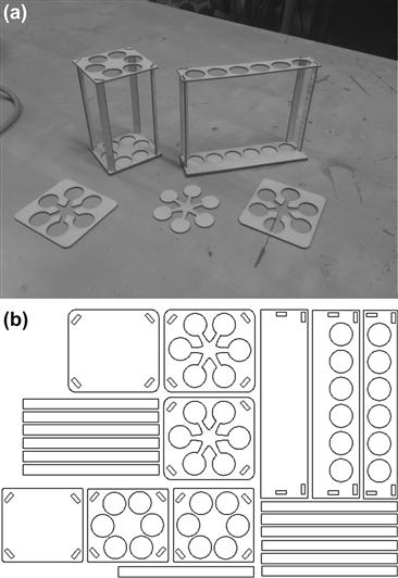
FIGURE 6.80 Laser cut test tube racks: (a) the cut and assembled rack and (b) the pattern for laser cutting.
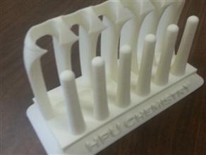
As complexity is free with the sharing of digital designs, it is just as easy to replicate an inexpensive test tube rack as it is to make an $850 magnetic rack. For example, Andrew Adey (Thingiverse user Acadey) is a graduate student in the Shendure Lab, University of Washington, Genome Sciences who became frustrated with the seemingly criminal charges for magnet racks.86 He designed a 96-well plate/0.2 ml strip tube magnet rack87 shown in Figure 6.82. It can perform magnetic bead separation for a 96-well plate, or alternatively, a 96-well plate with the wells cut out can be taped on top to hold eight tube strips. The magnets are available for about $6 a piece88, making it possible to justify the cost of a RepRap with a single (or at most two) standard commercial magnetic racks that normally run between $450 and $900. Similarly, he designed a magnetic rack for eight 1.5 ml tubes as shown in Figure 6.83, which can be put together with 70 cent magnets, saving you hundreds of dollars per rack.89 As we have seen throughout this book, open designs are iterative and are able to be easily built upon. The University of Washington plans on climbing the ladder of open-source sophistication and are obtaining a high-resolution printer for more fine-scale designs.90 They hope to build some machines for automated sample processing using 3-D printed items along with fluidics controlled by the open-source Raspberry Pis and Arduinos. You may want to consider helping them.
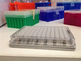
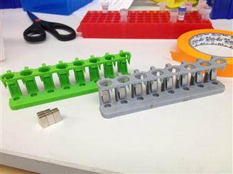
There are a growing number of organizations devoted to producing OSH for science. One such group is Hackteria.org,91 which was designed as a community platform to encourage the collaboration of scientists, hackers and artists to combine their expertises, share instructions on how to work with life science technologies, and cooperate on the organization of workshops, temporary labs, hack-sprints and meetings. It was started in 2009 by Andy Gracie, Marc Dusseiller and Yashas Shetty. What has developed is a rich wiki-based web resource for people interested in or developing projects that involve bioart, open-source software/hardware, DIY biology, art/science collaborations and electronic experimentation. For a feel of how Hackteria combines art and science, consider the Tardi-GelBox for electrophoresis designed by Thingiverse user dusjagr shown in Figure 6.84.92 The box is an open-source project that is laser cut and sports a tardigrade on it. Why a tardigrade? They are pretty cool,93 but I am not exactly sure. That perhaps is the point that Hackteria strives to make. With the collaborative open-source paradigm, not only can less-expensive high-performance tools be built and shared with the world, but at the same time, we can make them customized works of art to increase the aesthetic appeal, ability for our students to express themselves or just the general excitement for research in our laboratories. The Tardi-GelBox is laser cut in acrylic and made water tight with acryl-glue. After assembly, you simply cast your agar-gel, pour the running buffer (e.g. salt water), add your DNA samples, plug into a DC power supply (15–100 V) and enjoy. Hackteria has over 70 other low-cost DIY designs such as microscopes, microfluidics, incubators, spectrometers, bioprinting and more that are best accessed through their wiki.
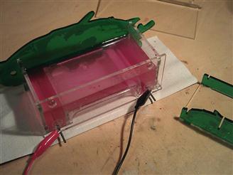
6.6 Chemistry: Spectrometers and Other Chemical Research Tools
OSH can also be used for chemistry and chemical engineering. In addition to the work of Symes et al. [15], which has demonstrated using a 3-D printer as reactionware for chemical synthesis in a way that makes open-source digital chemistry a reality, the open-source paradigm can make more conventional (yet less-expensive and customizable) chemical research equipment. In this section, we will look at designs for spectrometers and other research tools useful to those skilled in the chemical sciences. The results of the chemical equipment from the designs are discussed similarly to the last section to provide data for conclusions about future development of other open-source analytical tools discussed in Chapter 7.
6.6.1 Open-source spectrometers
One of the best examples of the OSH approach being applied to research equipment while also contributing to STEM outreach to bring more young people into the sciences is being performed by The Public Laboratory for Open Technology and Science (also known as Public Laboratory).94 The Public Laboratory mission is “Using inexpensive DIY techniques, we seek to change how people see the world in environmental, social, and political terms. We are activists, educators, technologists, and community organizers interested in new ways to promote action, intervention, and awareness through a participatory research model.” Thus, using inexpensive components and open-source software, Public Laboratory has developed an Android-based cell phone spectrometer with a range of 400–900 nm and a resolution of 3 nm [54]. The properties of the Public Laboratory spectrometer are comparable to those of a commercial mobile hand-held visible light spectrometer that costs over $2500.95 A screenshot of a cell phone equipped with the Public Laboratory Spectral Workbench software is shown in Figure 6.85.
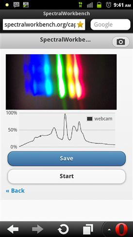
FIGURE 6.85 A screenshot of a cell phone equipped with the Public Laboratory Spectral Workbench software.
Public Laboratory maintains a detailed site for teaching everyone about spectroscopy. It also provides comprehensive instructions on how to build several varieties of spectrometers including (1) a foldable mini-spectrometer, (2) a smartphone spectrometer and (3) a desktop spectrometry kit along with all the necessary open-source software to analyze scans.96 The initial versions of the Public Laboratory spectrometers were made by crudely taping a small black paper case and a slice of DVD-R to the back of my Android97 phone. This worked, but they have progressed beyond these initial designs. Now using the powerful tool of open-source 3-D printing (discussed in Chapter 5 in detail), you can print a superior version of the Public Laboratory spectrometer (v3.0)98 as seen in Figure 6.86, which was released under an open-source CERN OHL v1.1 license.
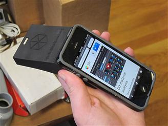
Public Laboratory ran a successful crowd-funding campaign for their spectroscopy project and now they offer a desktop spectrometry kit for $40. This again represents more than an order of magnitude decrease in spectroscopy costs for those already in possession of a computer or an appropriately endowed smartphone. This spectrometer greatly expands the potential users of spectroscopy. It again can be used to encourage interest in science and engineering in young people. For example, it can be used to identify dyes in laundry detergent, to test grow lamps, to probe water quality and to analyze food. Public Laboratory writes detailed protocols for each application, with the hope of making science more accessible and a part of everyday life [54].
Public Laboratory is not alone in investigating open-source spectroscopy. Myspectral has developed the Spectruino,99 which uses the Arduino platform (discussed in Chapter 4) to provide a UV/Vis/IR spectrometer, which measures light intensity as a function of wavelength with a combination of diffraction grating and a linear CCD camera. The Spectruino, which is partially open source, is shown in Figure 6.87.
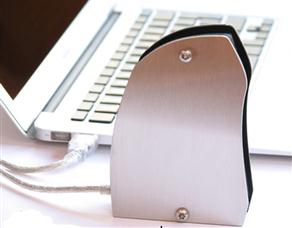
The Spectruino is more robustly built as it consists of a stainless steel and aluminum case. However, the design still suffers from the detector being fixed to the case with a material that is affected by temperature, which limits its use for some high-precision applications. This, of course, is only the beginning of open-source spectroscopy as the projects from Myspectral and Public Laboratory are growing and improving as more scientists add to the designs and software. For fans of Star Trek, it is pretty clear where we are going—and in fact we are already at the beginning stages of an open-source tricorder.100 Many of the Arduino-based scientific tools that have already been developed can be integrated together, so as each group or team of specialists continue to work on their own piece of the scientific puzzle, once it becomes developed enough, it will be possible to bring them all come together to form a tool that really is right out of the science fiction books. A very ambitious open-source Tricorder Project is now well into development.101 The Science Tricorder Mark 2 prototype sensor board shown in Figure 6.88 contains 10 different sensing modalities, organized into three main themes: atmospheric sensors (temperature, humidity, and pressure), electromagnetic sensors (magnetic flux, color, an IR thermometer, and ambient light levels), and spatial sensors (GPS location, ultrasonic distance sensor, accelerometer and a gyroscope).102 Again, this is only scratching the surface of what we can now do with sensor technology and there are many organizations pushing the technology forward.103 It is clear we will see more increasingly sophisticated open-source spectrometry projects in the near future.
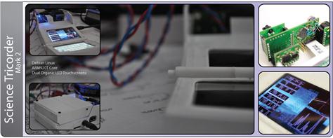
The open-source spectrometers significantly reduce the costs associated with many experiments that need them, while also enabling the production of highly customizable designs for specialized experiments. These reductions in costs and increases in flexibility are likely to boost technical development in any field that utilize spectrometers. At the same time that it assists the research community, it can also radically reduce the cost of education, amateur and DIY science [2]. This is thus likely to encourage more DIY scientists and young people to enter STEM fields [55,56]. These developments provide interesting possibilities in the future, where it is now quite possible to consider the general public performing their own real-time chemical analyses with their cell phones. Similar to the crowd-sourced data gathering with the Arduino-based Geiger counters, the public could provide highly reliable geographically tagged data on air, water and food quality, etc.
6.6.2 3-D printable chemical equipment
In the last section, we looked at various test tube racks and stands, which would be useful to chemists in addition to biologists, but there are also many other both simple and more advanced (and costly) 3-D printable components for chemistry laboratories. For example, consider the Buckner funnel and open-source printable example,104 of which is shown in MeshLab105 (open-source 3-D mesh processing software) Figure 6.89.
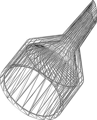
Buchner funnels are relatively common as they are used for vacuum-assisted filtration in all manner of experiments. On top of the funnel-shaped part, there is a cylinder with a perforated plate separating it from the funnel. The designer (Thingiverse user: chowderhead) made the OpenSCAD script parametric, so you can have any size of Buchner funnel you would like. All the dimensions of the Buckner funnel are based on the diameter of the filter paper you would like to use (as filter media comes in a variety of diameters). Because of the limitations of printing on most single-material 3-D printers, in this design, the necessary perforations are not included and thus need to be drilled afterward. However, in the near future, as many open-source 3-D printers are moving to two or more print heads, one of which can print a sacrificial support material like sugar or polyvinyl alcohol (PVA), I am confident that someone will design a one-step printable Buckner funnel. For the plate that needs drilled, it will need 100% infill, but if you are printing the holes, you can get away without using as much plastic. Also note that depending on the quality and fine tuning of your printer, you may have relatively porous walls. To eliminate this, as it would ruin the functionality of the funnel, you will need to seal it and depending on your printing material, there are several options. If you printed it in ABS, you can use a mixture of acetone and ABS (e.g. bad prints) to paint your funnel. Likewise PLA can be smoothed with a dip treatment in dichloromethane (CH2Cl2 or DCM).
It is also possible to take advantage of discarded equipment with the help of a laboratory 3-D printer to make other items you need around the lab. For example, consider the pipette stand106 designed by thingiverse user: M_Sanna shown in Figure 6.90.
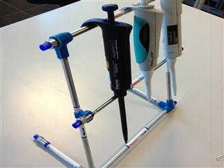
The ability to fabricate custom connectors makes it possible to use nonrefillable high-performance liquid chromatography (HPLC) columns as a constructor set to make the pipette rack. Pipette racks are probably not a major expense in your lab and usually cost $85–140, but again this is money perhaps better spent elsewhere. You do not need to stop there. You can make your own adjustable volume pipette107 as shown in Figure 6.91, which was developed by Dr Konrad Walus of the Department of Electrical and Computer Engineering at the University of British Columbia. He is well known in the maker community for his clever low-cost 3-D printable scientific designs for hobbyists (e.g. 3-D printable microscopes), but the broader aim of his research group is to develop printing technology that is capable of producing active electronic, mechanical, and chemically sensitive devices. This is the next stage in open-source 3-D printing as more complex, active, smart and functional materials are printed into objects turning them into sophisticated devices. In addition, his lab has already begun to look at biologically useful structures (e.g. programmatically defined tissues by 3-D printing multicellular assemblies) in new variations of the basic printing technology. His group is specifically targeting the fabrication of 3-D tissue constructs for use in drug screening and testing. The potential for enormous impact and radical improving while reducing the costs of modern medicine are staggering. Perhaps a final example shows how the Walus group is repaid for sharing. Following the open-source model, Walus’s adjustable volume pipette has already been simplified and improved and reshared108 as seen in the new design show in Figure 6.92 developed by Thingiverse user: aliekens.
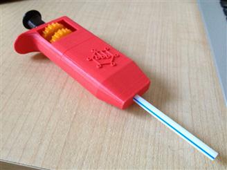
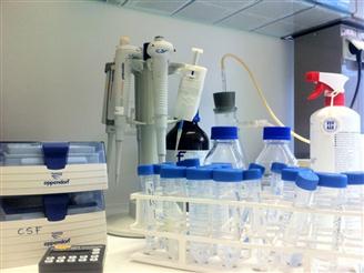
This version of Walus’s pipette has bulkier top components and is easier to print than the original, which extends the designs to a larger community of users. Aliekens’ primary modification was to remove the threaded bolt from the plunger in Walus’s design, and redesign the plunger so that a 75 mm M4 bolt could be inserted through the length of the plunger replacing the original thread. Because of this change, the thumb gears were also modified to accept the M4 rod. To ensure a closed surface, you should seal the membrane chamber with a few coats of ABS glue (ABS scraps mixed with acetone). In addition, this same ABS + acetone mixture should be used to fit the straw where the straw enters the seals, which eliminates any possibility of air escaping. Aliekens has successfully used a double membrane made of lab gloves with 200 μl tips to obtain below 10 μl consistency. This potentially replaces the pipettes that can cost several hundred dollars with a few dollars of materials and it will only get better. The future of open-source chemistry equipment is looking bright.
References
1. Jones R, Haufe P, Sells E, et al. RepRap – the replicating rapid prototyper. Robotica. 2011;29:177–191.
2. Pearce JM. Building research equipment with free, open-source hardware. Science. 2012;337:1303–1304.
3. Sells E, Bailard S, Smith Z, Bowyer A, Olliver V. RepRap: the replicating rapid prototyper-maximizing customizability by breeding the means of production. In: Pillar FT, Tseng MM, eds. Handbook of research in mass customization and personalization. New Jersey: World Scientific; 2009;568–580. Strategies and concepts vol. 1.
4. Dimiduk TG, Kosheleva EA, Kaz D, et al. A simple, inexpensive holographic microscope Digital holography and three-dimensional imaging Osa technical digest (CD). Opt Soc Am 2010;JMA38.
5. Sun R, Bouchard MB, Burgess SA, Radosevich AJ, Hillman EM. A low-cost, portable system for high-speed multispectral optical imaging Biomedical optics Osa technical digest (CD). Opt Soc Am 2010;BTuD41.
6. Teikari P, Najjar RP, Malkki H, et al. An inexpensive Arduino-based LED stimulator system for vision research. J Neurosci Methods. 2012;211:227–236.
7. Zhang C, Anzalone NC, Faria RP, Pearce JM. Open-source 3D-printable optics equipment. PLoS One. 2013;8(3):e59840. doi 10.1371/journal.pone.0059840.
8. Jones RO, Iravani P, Bowyer A. Rapid manufacturing of functional engineering components. Bath, UK: University of Bath; 2012.
9. Baechler C, DeVuono M, Pearce JM. Distributed recycling of waste polymer into RepRap feedstock. Rapid Prototyping J. 2013;19:118–125.
10. Kreiger M, Pearce JM. Environmental impacts of distributed manufacturing from 3-D printing of polymer components and products. MRS Online Proc Libr. 2013;1492 mrsf12-1492-g01-02.
11. Pearce JM, Blair CM, Laciak KJ, Andrews R, Nosrat A, Zelenika-Zovko I. 3-D printing of open source appropriate technologies for self-directed sustainable development. J Sustainable Dev. 2010;3:17.
12. Kreiger M, Anzalone GC, Mulder ML, Glover A, M Pearce J. Distributed recycling of post-consumer plastic waste in rural areas. MRS Online Proc Libr. 2013;1492 mrsf12-1492-g04-06.
13. Pearce JM. Make nanotechnology research open-source. Nature. 2012;491:519–521.
14. Pearce JM. Open-source nanotechnology: solutions to a modern intellectual property tragedy. Nano Today. Available online 2013 http://dx.doi.org/10.1016/j.nantod.2013.04.001.
15. Symes MD, Kitson PJ, Yan J, et al. Integrated 3D-printed reactionware for chemical synthesis and analysis. Nat Chem. 2012;4:349–354.
16. Cardona A, Saalfeld S, Schindelin J, et al. TrakEM2 software for neural circuit reconstruction. PLoS One. 2012;7:e38011.
17. Kumar K, Desai V, Cheng L, et al. AGeS: a software system for microbial genome sequence annotation. PLoS One. 2011;6:e17469.
18. Christian W, Esquembre F, Barbato L. Open source physics. Science. 2011;334:1077–1078.
19. Marzullo TC, Gage GJ. The SpikerBox: a low cost, open-source bioamplifier for increasing public participation in neuroscience inquiry. PLoS One. 2012;7:e30837.
20. Pearce JM. The case for open source appropriate technology. Environ, Dev Sustainability. 2012;14:425–431.
21. Stokstad E. Open-source ecology takes root across the world. Science. 2011;334:308–309.
22. Bruns B. Open sourcing nanotechnology research and development: issues and opportunities. Nanotechnology. 2001;12:198–210.
23. Mushtaq U, Pearce JM. Open source appropriate nanotechnology. In: Maclurcan D, Radywyl N, eds. Nanotechnology and global sustainability. 2012;191–213.
24. Nielsen M. Reinventing discovery: the new era of networked science. Princeton University Press 2011.
25. Lang T. Advancing global health research through digital technology and sharing data. Science. 2011;331:714–717.
26. Glynn LH, Hallgren KA, Houck JM, Moyers TB. Cacti: free, open-source software for the sequential coding of behavioral interactions. PLoS One. 2012;7:e39740.
27. Denkenberger DC, Brandemuehl MJ, Pearce JM, Zhai J. Expanded microchannel heat exchanger: design, fabrication and preliminary experimental test. Proc Inst Mech Eng, Part A. 2012;226:532–544.
28. Denkenberger DC, Pearce JM. Compound parabolic concentrators for solar water heat pasteurization: numerical simulation. In: Proceedings of the 2006 international conference of solar cooking and food processing. 2006;108.
29. Brasor P. Public wary of official optimism. The Japan Times Sunday, March 11, 2012.
30. You Can View Official EPA Radiation Readings. Washington post. Available from: http://www.washingtonsblog.com/2011/03/you-can-view-official-epa-radiation-readings.html.
31. Japan Geigermap: At-a-glance. Available from: http://japan.failedrobot.com/.
32. Pearce JM. Limitations of nuclear power as a sustainable energy source. Sustainability. 2012;4(6):1173–1187.
33. Burke J, Estrin D, Hansen M, et al. Participatory sensing. In: Proceedings of the workshop on the world-sensor-web (WSW’06), mobile device centric sensor networks and applications. 2006;117–134. Boulder, Colorado.
34. Crooks A, Croitoru A, Stefanidis A, Radzikowski J. Earthquake: twitter as a distributed sensor system. Trans GIS. 2013;17(1):124–147.
35. Settle FA. Topics in chemical instrumentation, evolution of instrumentation for UV-visible spectrophotometry. J Chem Educ 1986;A216–A223.
36. Popov-Raljić JV, Mastilović JS, Laličić-Petronijević JG, Popov VS. Investigations of bread production with postponed staling applying instrumental measurements of bread crumb color. Sensors. 2009;9:8613–8623.
37. Popov-Raljić JV, Laličić-Petronijević JG. Sensory properties and color measurements of dietary chocolates with different compositions during storage for up to 360 days. Sensors. 2009;9:1996–2016.
38. Popov-Raljić JV, Lakić NS, Laličić-Petronijević JG, Barać MB, Sikimić VM. Color changes of UHT milk during storage. Sensors. 2008;8:5961–5974.
39. Bogue R. Optical chemical sensors for industrial applications. Sensor Rev. 2007;27(2):86–90.
40. Terry PA. Application of ozone and oxygen to reduce chemical oxygen demand and hydrogen sulfide from recovered paper processing plant. Int J Chem Eng 2010;. doi 10.1155/2010/250235 Article ID 250235, 6 pages.
41. Elliot AM. A photoelectric colorimeter for estimating protozoan population densities. Trans Am Microscopial Soc. 1949;68:228–233.
42. Eckhardt L, Mayer JA, Creech L, Johnston MR, et al. Assessing children’s ultraviolet radiation exposure: the potential usefulness of a colorimeter. Am J Public Health. 1996;86:1802–1804.
43. Trujillo O, Vanezis P, Cermignani M. Photometric assessment of skin colour and lightness using a tristimulus colorimeter: reliability of inter and intra-investigator observations in healthy adult volunteers. Forensic Sci Int. 1996;81:1–110.
44. Pesce S. Use of water quality indices to verify the impact of Córdoba City (Argentina) on Suquía River. Water Res. 2000;34:2915–2926.
45. Hur J, Lee BM, Lee TH, Park DH. Estimation of biological oxygen demand and chemical oxygen demand for combined sewer systems using synchronous fluorescence spectra. Sensors. 2010;10:2460–2471.
46. Hur J, Cho J. Prediction of BOD, COD, and total nitrogen concentrations in a typical urban river using a fluorescence excitation-emission matrix with PARAFAC and UV absorption indices. Sensors. 2012;12:972–986.
47. Anzalone GC, Glover AG, Pearce JM. Open-source colorimeter. Sensors. 2013;13(4):5338–5346. doi 10.3390/s130405338.
48. United States Environmental Protection Agency. Methods for chemical analysis of water and wastes. US EPA 1983.
49. Gonzales J. Wastewater treatment in the fishery industry. Food and Agriculture Organization of the United Nations 1995.
50. Hach Company. Oxygen demand, chemical, method 8000 for water, wastewater and seawater. Available from: http://www.hach.com/asset-get.download.jsa?Id=7639983640.
51. Pearce JM, Grafman L, Colledge T, Ryan L. Leveraging information technology, social entrepreneurship and global collaboration for just sustainable development. In: Proceedings of the twelfth annual national collegiate inventors and innovators alliance conference. 2008;201–210.
52. Buitenhuis AJ, Zelenika I, Pearce JM. Open design-based strategies to enhance appropriate technology development. In: Proceedings of the fourteenth annual national collegiate inventors and innovators alliance conference: open. March 25–27, 2010;1–112.
53. Pearce JM, Albritton S, Grant G, Steed G, Zelenika I. A new model for enabling innovation in appropriate technology for sustainable development. Sustainability: Sci, Pract Policy. 2012;8(2):42–53.
54. Warren J. Mobile (Android) version of spectral workbench. The Public Laboratory 2012; Available from: http://publiclaboratory.org/notes/warren/6-12-2012/mobile-android-version-spectral-workbench; 2012; [accessed 19.10.12].
55. Williams A, Gibb A, Weekly D. Research with a hacker ethos: what DIY means for tangible interaction research. Interactions. 2012;19:14.
56. Buechley L, Hill BM. LilyPad in the wild: how hardware’s long tail is supporting new engineering and design communities. MIT 2010.
57. President’s Commission on the Accident at Three Mile Island. The need for change, the legacy of TMI: report of the President’s commission on the accident at three Mile Island. Washington, DC, USA: President’s Commission; 1979.
58. Thompson J, Thompson R, Bear D. TMI assessment, part 2. 1995; Available from:[accessed 11.04.12] http://www.southernstudies.org/images/sitepieces/ThompsonTMIassessment.pdf; 1995.
59. Gundersen A. Three myths of the Three Mile Island accident, lecture. Burlington, Vermont, USA: Fairewinds Energy Education Corp; 2009.
60. Hatch MC, Beyea J, Nieves JW, Susser M. Cancer near the Three Mile Island nuclear plant: radiation emissions. Am J Epidemiol. 1990;132(3):397–417.
61. Wing S, Richardson D, Armstrong D, Crawford-Brown D. A reevaluation of cancer incidence near the Three Mile Island nuclear plant: the collision of evidence and assumptions. Environ Health Perspect. 1997;105:52–57.
62. Hatch MC, Wallenstein S, Beyea J, Nieves JW, Susser M. Cancer rates after the Three Mile Island nuclear accident and proximity of residence to the plant. Am J Epidemiol. 1991;81(6):719–724.
63. Gur D, Good WF, Tokuhata GK, Goldhaber MK, Rosen JC, Rao GR. Radiation dose assignment to individuals residing near the Three Mile Island nuclear station. Proc PA Acad Sci. 1983;57:99–102.
64. Talbott EO, Youk AO, McHugh KP, et al. Mortality among the residents of the Three Mile Island accident area: 1979–1992. Environ Health Perspect. 2000;108:545–552.
65. Wing S, Richardson D. Collision of evidence and assumptions: TMI déjà view. Environ Health Perspect. 2000;108:A546–A547.
66. Talbott EO, Zhang A, Youk AO, McHugh-Pemu KP, Zborowski JV. Re: “Collision of evidence and assumptions: TMI déjà view.”. Environ Health Perspect. 2000;108:A547–A549.
1OpenSCAD http://www.openscad.org.
2There are many other free and open-source CAD tools available such as BRL-CAD, Blender CAD, Python CAD, OpenCASCADE, FreeCAD, HeeksCAD, Wings3D, and Shapesmith. In addition, there are some open-source drawing packages like Art of Illusion and Blender, which are useful. Finally, there are free but closed-source tools like Google Sketchup and TinkerCAD.
As of this writing, none of the open-source CAD packages are as advanced as the commercial CAD software that, for example, mechanical engineering students are accustomed to using (e.g. Solid Works, NX, AutoCAD, Inventor, etc.). If you have a student researcher already familiar with these tools, it may save your group time in the short term to do your designs in closed software and if you still post the STLs, they may still be somewhat useful to the open-source community. However, to take complete advantage of the open-source paradigm, which will build upon and improve your designs for your benefit, the tools that are used to create the designs also need to be open so you are including the greatest possible number of collaborators.
It is also interesting to note as 3-D printing expands the number of software developers assisting on the open-source CAD packages will expand, and if history is a basis of what will happen in the future, the open-source packages will surpass what is available both now and in the future in closed form.
3Customizable gasket http://www.thingiverse.com/thing:58665.
4OpenSCAD User Manual http://en.wikibooks.org/wiki/OpenSCAD_User_Manual.
5For more information about coding for the Customizer, see http://www.makerbot.com/blog/2013/01/23/openscad-design-tips-how-to-make-a-customizable-thing/.
6Optical Chopper Wheel http://www.thingiverse.com/thing:28121.
7Skeinforge http://fabmetheus.crsndoo.com/wiki/index.php/Skeinforge.
8Cura http://daid.github.com/Cura/.
9Slic3r http://slic3r.org.
10RepRap http://reprap.org.
11Acrylonitrile-butadiene-styrene (ABS) and polylactic acid (PLA) polymers are the two most readily available and mature printing filament materials although many others are available and under development as discussed in the last chapter.
12Open-source automated filter wheel http://www.thingiverse.com/thing:26553.
13Arduino http://www.arduino.cc.
14OpenBeam http://openbeamusa.com/.
15For those of you that just built a RepRap following the instructions in Chapter 5, you probably have a lot of M3-sized components left over.
16Open-source Optical Rail from OpenBeam—Magnetic Base http://www.thingiverse.com/thing:30729.
17OpenBeam T Bracket http://www.thingiverse.com/thing:30524.
18OpenBeam Optical Rail Simple Rod Holder http://www.thingiverse.com/thing:31370.
19Open-source Optical Rail Mount for OpenBeam http://www.thingiverse.com/thing:30491.
20Open-source magnetic optics base http://www.thingiverse.com/thing:28133.
21Square Filter Holder for Open-source Optics http://www.thingiverse.com/thing:31483.
22Open-source round lens holder http://www.thingiverse.com/thing:26752.
23Kinematic mirror/lens mount http://www.thingiverse.com/thing:30727.
24Open-source fiber optic holder http://www.thingiverse.com/thing:28187.
25Screen holder for OpenBeam optical rail http://www.thingiverse.com/thing:31403.
26Simple semiconductor sample holder v3 http://www.thingiverse.com/thing:30688.
27Open-source lab jack http://www.thingiverse.com/thing:28298.
28Automated open-source automated filter wheel http://www.thingiverse.com/thing:26553.
29Collection of 3D printable open-source optics equipment http://www.thingiverse.com/jpearce/collections/open-source-optics
30Optical Mounts http://www.thingiverse.com/thing:38062.
31Recyclebot controls http://www.thingiverse.com/thing:54180 and mechanical system http://www.thingiverse.com/thing:12948
32At the time of this writing, it appears the United States may be joining this category as well. Regardless, I doubt there are many working scientists that feel science is overfunded.
33See, for example, our open-source solar-powered RepRap design http://www.thingiverse.com/thing:74671 and project page http://www.appropedia.org/Mobile_Solar_Powered_3D_Printer_V2.0.
34Peter Jansen http://www.tricorderproject.org/aboutpeter.html.
35Commercial SLS systems can easily cost more than $500,000, so that still provides a lot of capital for a good laser source and optics.
363D-Printable Laser Cutter http://www.thingiverse.com/thing:11653.
37Buildlog 2× Laser Cutter http://www.buildlog.net/blog/2011/02/buildlog-net-2-x-laser/.
38Open-source laser polymer welding system http://www.thingiverse.com/thing:28078.
39Open-source laser polymer welding system wiki page http://www.appropedia.org/Open-source_laser_system_for_polymeric_welding.
40Details in using Arduino’s are in Chapter 4. Everything you need is available http://www.arduino.cc/
41These devices are not open source. Many times, even when developing open-source hardware for your laboratory, until the OSH field is more mature, specialized closed components will need to be acquired and integrated into a solution. As the OSH community develops, this will become less necessary and the costs of these hybrid types of scientific tools will be further reduced.
42Hydra http://sourceforge.net/projects/lasersystemforp/.
43Processing http://processing.org/.
44Inkscape http://inkscape.org/download/?lang=en.
45GCodeTools for Inkscape http://www.cnc-club.ru/forum/viewtopic.php?t=62#top1.
46Template example http://www.appropedia.org/File:MOST_laserweld_TEMPLATE.svg.
47You are, of course, unlikely to get a perfect weld the first time and you will need to do some trial and error investigation into your hardware variables (e.g. laser optics, motor speed, time and intensity of laser power, etc.).
48Protocol page http://www.appropedia.org/Laser_welding_protocol:_MOST
49Geiger counter—Radiation Sensor Board for Arduino http://www.cooking-hacks.com/index.php/documentation/tutorials/geiger-counter-arduino-radiation-sensor-board.
50Geiger counter circuit https://sites.google.com/site/diygeigercounter/circuit-description.
51DIY Geiger counter kit https://sites.google.com/site/diygeigercounter/home.
52Case designed for the DIYGeigerCounter v.4.1 http://www.thingiverse.com/thing:36678.
53Consider Pennsylvania’s Three Mile Island nuclear incident several decades ago. There is now substantial evidence that the releases were underreported to the public by officials by at least an order of magnitude. The official Nuclear Regulatory Commission (NRC) value is 10 MCi [57]. Thompson et al. quote more than double that at 22 MCi [58], whereas Gundersen points out that the sum of the NRC releases yields 36 MCi and estimates anywhere between 100 and 1000 times the NRC value [59]. The bottom line perhaps comes from a raft of epidemiological studies, which point to a significant epidemic of cancer that is clearly related to the Three Mile Island release and that would not have occurred if the official NRC values were accurate [60–66].
54There is already an Android App that can turn your cell phone into a radiation detector using the CMOS camera covered by a piece of tape http://hackaday.com/2012/01/15/turn-your-camera-phone-into-a-geiger-counter/ and Softbank launched a smartphone that tracks radiation specifically for Japan http://news.cnet.com/8301-1035_3-57444283-94/softbanks-geiger-counter-smartphone-start-of-a-global-trend/.
55Xoscillo https://code.google.com/p/xoscillo/.
56Open-source colorimeter STL and SCAD files http://www.thingiverse.com/thing:45443.
57Open-source colorimeter wiki page http://www.appropedia.org/Open-source_colorimeter.
58Adadfruit https://www.adafruit.com/.
59Fritzing is an open-source hardware initiative to support designers, artists, researchers and hobbyists to work creatively with interactive electronics. Fritzing has created (and is improving) a software tool, a community website and services in the spirit of Processing and Arduino, fostering an ecosystem that allows users to document their prototypes, share them with others, teach electronics in a classroom, and layout and manufacture professional printed circuit boards (PCBs). http://fritzing.org/.
60You can follow updates to the pHduino development on Carlos’s blog. http://phduino.blogspot.com/.
61Freeduino is a collaborative open-source project to replicate and publish Arduino-compatible hardware files. The Freeduino Eagle SCH, BRD and Gerber production files allow users to create boards that are 100% functionally, electrically and physically compatible with Arduino hardware. While Arduino is a protected trademark, Freeduino comes with a free and unrestricted license to use the Freeduino name, available for any use. This means you can do whatever you want with their files. The idea here is to make available the Eagle files you would need to make your own Freeduino variant board. So, for example, you could make a simpler board specifically for the open-source colorimeter or the pH meter in this chapter. For more information, see http://www.freeduino.org/about.html.
62Freeduino designs http://www.freeduino.org/freeduino_open_designs.html.
63pHduino Datalogger http://code.google.com/p/phduino/wiki/pHduinoDatalogger.
64Open PCR http://openpcr.org/.
65OpenPCR software http://github.com/jperfetto/OpenPCR.
66OpenPCR CAD files http://download.openpcr.org/design/OpenPCR-CAD-1.0.zip.
67OpenPCR board http://download.openpcr.org/design/OpenPCR-BoardDesign-1.0.zip.
68Open PCR BOM https://docs.google.com/spreadsheet/ccc?key=0AiaWH3PL_9CndG1GbmtSZ1I3aGdkQkE4YVhwZ3o5c1E#gid=.
69That may be much faster than commentators have predicted. Our group (along with many others) is planning to build low-cost open-source 3-D printers for metal in the short term.
70DremelFuge http://www.thingiverse.com/thing:1483.
71DIY BIO http://diybio.org/.
72For those of you that have not put together a RepRap following the directions in Chapter 5, you can still get your hands on 3-D printed objects using a commercial printing service like Shapeways. Here is the link for the DremelFuge http://shapeways.com/shops/labsfromfabs.
73Centrifuges require some care in order to be used safely, and a printed centrifuge in particular will have hazards that you should be ready for if you try to use it. Consult your laboratory’s safety officer before using this device and always wear your safety glasses.
74Microcentrifuge http://www.thingiverse.com/thing:33818.
75This can also be accomplished printing with a 2-headed RepRap and using PVA as a support printing material.
76USB powered cytocentrifuge http://www.thingiverse.com/thing:46448.
77Dr. Richard Siderits’ designs http://www.thingiverse.com/siderits/designs.
783-D printable rapid fluid filters http://www.thingiverse.com/thing:27933.
79PCR tube racks http://www.thingiverse.com/thing:25450.
80Cassette rack http://www.thingiverse.com/thing:28575.
81Platypus Forcep http://www.thingiverse.com/thing:31868.
82Makerbeam: http://www.makerbeam.eu/.
83Connectors for 20 mm MakerBeam http://www.thingiverse.com/thing:28179.
84Laser cut test tube racks http://www.thingiverse.com/thing:22728.
853-D Printable test tube racks http://www.thingiverse.com/thing:69911.
86Acadey Designs http://www.thingiverse.com/acadey/designs.
8796-well plate/0.2 ml strip tube magnet rack http://www.thingiverse.com/thing:79430.
88K&J Magnetics http://www.kjmagnetics.com/proddetail.asp?prod=BZ082.
89Magnetic Rack for 8, 1.5 ml tubes http://www.thingiverse.com/thing:79424.
90It should be noted that the RepRap community is also pushing the resolution of low-cost 3-D printers down, as well as diversifying the printable feedstock to all of the material families (e.g. ceramics and metals).
91Hackteria http://hackteria.org/.
92Tardi-GelBox http://www.thingiverse.com/thing:71638.
93These water-dwelling 1-mm-long eight-legged creatures sometimes called water bears are one of the most complex of all known polyextremophiles that can survive in horrendous conditions. For example, tardigrades can withstand temperatures from just above absolute zero to well above the boiling point of water, as well as extreme pressures, solar radiation, gamma radiation, ionic radiation and have even lived through the vacuum of space. A lot of people would consider this pretty cool. May be you do not. That is ok because you now have the ability to turn all your scientific equipment into works of art with your own favorite creatures.
94Public Laboratory http://publiclaboratory.org/home.
95Public Laboratory Visible Light Spectrometer http://publiclaboratory.org/notes/warren/11-57-2011/visible-light-spectrometer-2660-4-7nm-bandwidth.
96Public Laboratory Spectrometer http://publiclaboratory.org/tool/spectrometer.
97Android is also an open-source Linux-based operating system (provided by Google under the Apache License) designed primarily for smartphones and tablets and touchscreen mobile devices. For full details, see http://source.android.com/.
98Public Laboratory spectrometer (v3.0) http://www.thingiverse.com/thing:49934.
99Spectruino http://myspectral.com/#technical.
100In the Star Trek series and movies, a tricorder is a multifunction hand-held device used for sensor scanning, data analysis, and recording data. There are all different flavors of tricorders—such as those for engineering, planet exploration, and medical diagnosis.
101The Tricorder Project http://www.tricorderproject.org/.
102The Tricorder Project Mark 2 http://www.tricorderproject.org/tricorder-mark2.html.
103For example, there is the Tricorder X Prize, a $10 million competition to develop a hand-held portable, wireless device that monitors and diagnoses your health conditions to allow unprecedented access to personal health metrics. http://www.qualcommtricorderxprize.org/.
104Buckner funnel http://www.thingiverse.com/thing:25188.
105Meshlab http://meshlab.sourceforge.net/.
106Pipette stand http://www.thingiverse.com/thing:91209.
107Adjustable volume pipette http://www.thingiverse.com/thing:64977.
108Adjustable Volume Straw Pipette (simpler plunger) http://www.thingiverse.com/thing:74502.