Chapter 1
Getting Started
The Autodesk® Roadway Design for InfraWorks® 360 software is a vertical application that runs within the Autodesk® InfraWorks® 360 program. It provides additional functionality for designing roads from an engineering perspective rather than the preliminary layout and visualization perspective that is provided by the basic InfraWorks technology. It is a powerful tool for anyone who understands roadway engineering principles and is laying out roads with the InfraWorks 360 program.
Understanding the Capabilities of Roadway Design for InfraWorks 360
The Roadway Design for InfraWorks 360 vertical application extends the capabilities of the InfraWorks 360 program by offering advanced design and analysis tools for roadway design. The following sections break down these capabilities into several major areas.
Engineering Geometry
The roads you create with the InfraWorks core tools do not employ geometry that is consistent with civil engineering practices. These roads are considered to be “sketched” objects that are based on spline geometry. With the Roadway Design for InfraWorks 360 vertical application, you will be creating roads that are defined by horizontal curves, spirals, vertical curves, and other characteristics that meet the standards of engineered roads. You will have access to many tools that allow you to view and edit these engineering-based geometric properties. These tools include specialized gizmos, additional asset cards, additional panels, and others. In Figure 1.1, you see the PI, PC, and PT gizmos (if you don't know what these abbreviations mean, refer to the “P-What?” sidebar), which indicate the geometry of an engineered horizontal curve, along with a Road asset card showing design speed, design standards, and other information. This technology enables you to create much more sophisticated roads than the sketches created by the basic InfraWorks tools.
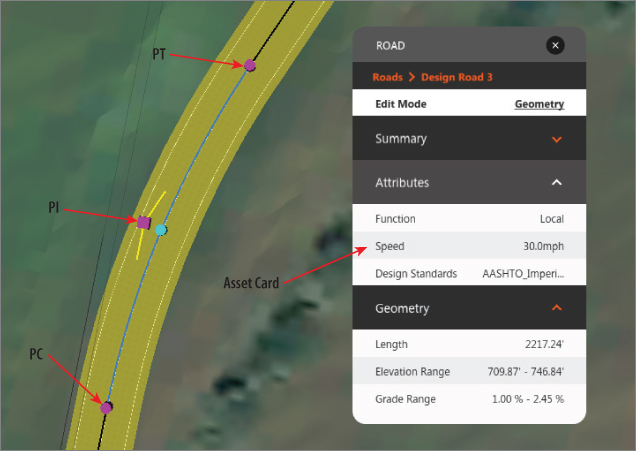
Figure 1.1 An engineered curve and its associated asset card
Rules-Based Design
When you create roads with the tools provided in the Roadway Design for InfraWorks 360 module, design standards are built in. At the time this book was written, the only standard available in the software was AASHTO 2011, but the availability of additional standards is expected. When you create a road, you choose from several classifications (see Figure 1.2). Based on the classification you choose, a design speed is assigned that then automatically determines horizontal and vertical geometry for your road. In other words, as you click points on the screen, the software is automatically designing the road for you.
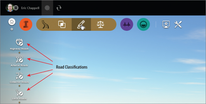
Figure 1.2 The road classification options
Profiles
If you have designed roads before, perhaps using AutoCAD® Civil 3D®, you know that the profile view is a critical tool in any road design. The Roadway Design for InfraWorks 360 vertical application provides the Profile View panel (see Figure 1.3), where you can view your design and have a complete set of tools for modifying the design in profile view.
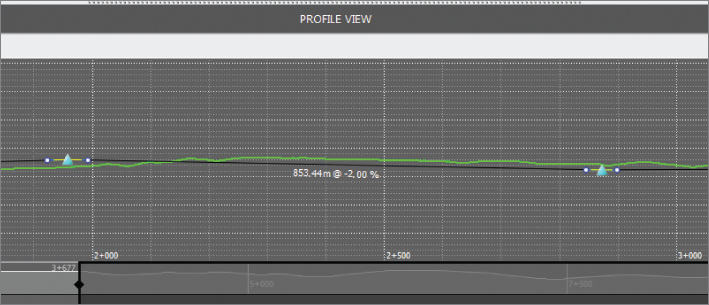
Figure 1.3 The Profile View panel
Intersections
Intersection design is often one of the most challenging aspects of any road design. In the basic InfraWorks program, the software handles road intersections to some extent, but only a limited amount of control is afforded to the user. Roadway Design for InfraWorks 360 technology enables the design of intersections through specialized gizmos and asset cards. Figure 1.4 shows a three-way intersection with the Intersection asset card. Notice the option where you can select a design vehicle and the InfraWorks software will automatically design the intersection geometry based on your choice.
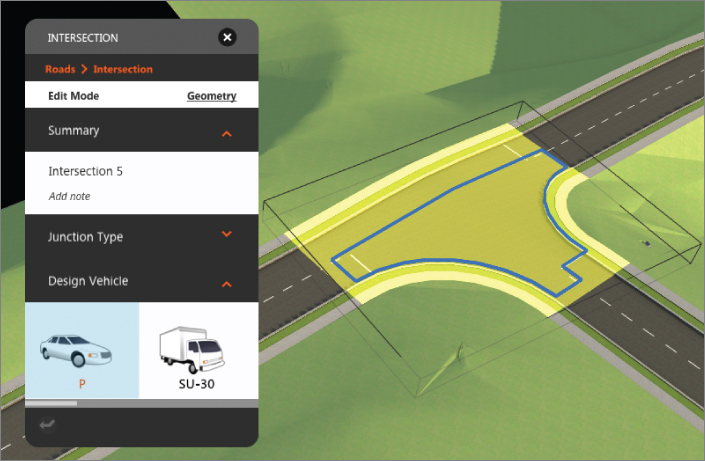
Figure 1.4 A specialized asset card for intersections
Sight Distance Analysis
One of the most important aspects driving the design of a road is sight distance. With the Roadway Design for InfraWorks 360 vertical application, you can perform a sight distance analysis for a road that will assess the geometry of the road as well as components of the model that may serve as obstructions. The analysis provides useful graphical and textual feedback in the forms of colored bands, tooltips, and sight pins. Figure 1.5 shows a sight distance analysis that highlights an accident zone and an area of sight failure.
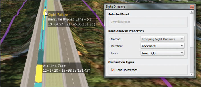
Figure 1.5 A sight distance analysis
Profile Optimization
Earthwork is another critical aspect in performing road design, one that dramatically affects cost. The Roadway Design for InfraWorks 360 vertical application provides a powerful optimization tool that will analyze and adjust your road profile to minimize the costs associated with earthmoving. Because of the computing power required to perform an optimization, the calculations are performed in the cloud. Your design is uploaded to InfraWorks 360 cloud services analyzed, and adjusted, and a new profile is sent to you when the optimization is complete. This new profile is accompanied by a report describing the resulting geometry along with a detailed earthwork and cost analysis. Figure 1.6 shows the Profile Optimization panel where an optimization is configured.
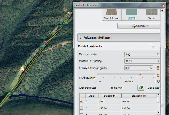
Figure 1.6 A profile optimization
Generate Civil 3D Drawings
When your InfraWorks design is complete and you're ready to move on to detailed design and documentation, the Roadway Design for InfraWorks 360 vertical application provides a tool that will automate the process of converting your InfraWorks model into a series of DWG files that can be opened within the Autodesk AutoCAD Civil 3D program. Figure 1.7 shows a plan and profile drawing generated by the View Civil 3D Drawings command in the InfraWorks program. The command not only has created the necessary drawing files, but it has also created Civil 3D alignments and profiles, and has generated a series of plan and profile sheets complete with properly configured viewports.

Figure 1.7 A Civil 3D plan and profile drawing generated by the InfraWorks program
Navigating Roadway Design for InfraWorks 360
The user interface for the Roadway Design for InfraWorks 360 vertical application is provided as its own set of Intelligent Tools. The main icon for these Intelligent Tools appears at the top left of the InfraWorks window as a tan circular icon with the Design, Review And Engineer Roads tooltip, as shown in Figure 1.8.
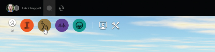
Figure 1.8 The Roadway Design icon
When you click the Roadway Design icon, it expands to reveal a toolbar containing three icons, as shown in Figure 1.9. I'll refer to this as the Roadway Design toolbar and the individual icons contained within it as the Analysis, Design, and Review icons.
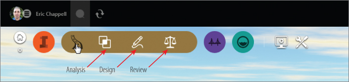
Figure 1.9 The expanded view of the Roadway Design toolbar
Each of the icons on this toolbar opens another toolbar on the side of the InfraWorks window. The following sections cover the toolbars and the tools on them.
Analysis Toolbar

On this toolbar, you will find tools for analyzing your model.

Terrain Themes Terrain Themes is a basic InfraWorks command. It opens the Terrain Themes panel, where you can configure a theme to color-code a terrain based on elevation, slope, or aspect (direction in which hillsides face).

Traffic Simulation This command is a preview feature and will not be covered in this book.

Profile Optimization Use this command to have the InfraWorks 360 program calculate the best profile design for your road based on cost, as well as design considerations such as maximum grade and PVI frequency.
Sun & Sky Sun & Sky is a basic InfraWorks command. It opens the Sun & Sky asset card, where you can adjust the appearance of light, shadow, and sky animation.
Design Toolbar

On this toolbar, you will find tools for creating new designs.

Highway Roads This command launches road layouts using the Highway design classification. This classification uses the highest design speed, resulting in larger horizontal curve radii, longer vertical curves, and other geometric properties consistent with high-speed roads. The design speed for the Highway classification is 70 mph (110 km/h).

Arterial Roads This command launches road layouts using the Arterial design classification. This classification is typically used for high-volume urban roads. The design speed is 50 mph (80 km/h).

Collector Roads This command launches road layouts using the Collector design classification. This classification is typically used for low-volume urban roads that provide access to residential areas. The design speed is 40 mph (60 km/h).

Local Roads This command launches road layouts using the Local Road design classification. This classification is typically used for low-volume urban roads that provide access to individual residential properties. The design speed is 30 mph (45 km/h).

City Furniture This is a basic InfraWorks command. It allows you to add detail to your model by inserting 3D models of things such as light poles, cars, people, and a whole list of other items. Plus, you can include your own 3D models, so just about anything can be added to your model as city furniture.

Coverages This is a basic InfraWorks function. You can think of a coverage as an area of land that is covered with something. That can be grass, pavement, concrete, sand, or just about anything. Coverages can also be used to shape the land they cover.

Points Of Interest This is a basic InfraWorks command. Create a point of interest to call out an important location in your model. Any 3D model can be used as a marker for a point of interest.

Style Palette The appearance of objects in an InfraWorks design is controlled by styles. Every InfraWorks model has a library of styles that you can pull from and apply to objects to quickly change their appearance. The Style Palette presents that library to you in an organized fashion.

Review Toolbar
On this toolbar, you will find tools for reviewing, analyzing, and exporting your design.

Profile View This tool opens the Profile View panel, where you can view and edit a road design in profile view. From here, you can adjust PVI locations and elevations, add new PVIs, and edit vertical curves.

Traffic Simulation This command is a preview feature and will not be covered in this book.

Sight Distance Analysis This command opens the Sight Distance panel, where you can configure and run a sight distance analysis. Through a series of visual feedback and tooltips, the analysis will tell you where there are sight distance failures and accident zones.

Surface Opacity This is a basic InfraWorks feature. It is a handy toggle that switches your terrain surface from see-through to opaque. It is great for working on underground features such as pipes or bridge foundations.

Sun & Sky Sun & Sky is a basic InfraWorks command. It opens the Sun & Sky asset card, where you can adjust the appearance of light, shadow, and sky animation.

Profile Optimization This command opens the Profile Optimization panel, where you make choices and set values related to design constraints, quantities, cost, and construction rules. Once you've made your choices and run the optimization, pertinent data from the model is uploaded to the cloud via the InfraWorks 360 program. Then, after the data is processed, a revised profile and an optimization report are sent to you.

Civil 3D Drawings This command opens the Create Civil 3D Drawings dialog where you configure the options for creating drawings of your road design. From here, you select the road you want to export, configure the area of the surface that will be included, and provide information that will configure the resulting drawing files and sheets.

Job Monitor This command opens the Job Monitor panel, where you can check on jobs that you have submitted using the Profile Optimization command. Here you can find the status of the jobs and download the resulting output when a job is complete.
Exercise 1.1: Explore the Roadway Design for InfraWorks 360 Software
To begin this exercise, go to the book's web page at www.sybex.com/go/roadwaydesignessentials2e and download the files for Chapter 1. Using the instructions in the Introduction, unzip the files to the correct location on your hard drive.

- Launch the InfraWorks 360 program.
- On InfraWorks 360 Home, click Open.
- Browse to
C:\InfraWorks Roadway Essentials\Chapter 01\and selectCh01 Bimsville Roads.sqlite. Click Open.You are looking at a model of the Bimsville Bypass project. If you have worked through the book Autodesk® InfraWorks 360® and InfraWorks® 360 LT Essentials, then you are quite familiar with this project. In this version of the model, only a portion of the bypass has been created.

- Click the Bookmarks icon on the Utility Bar; then click Bridge Plan to restore that bookmark.
You are looking at a bridge in a top-down, or plan view, orientation.
- Click the road to select it.
The road should highlight in yellow, and the Road asset card should appear immediately, as shown in Figure 1.10, although the Summary and Attributes sections may not be expanded in your view.

- With the road still selected, click Edit on the Utility Bar if it is not already enabled (white).
- Zoom out so that you can see the gizmos associated with the curve to the north of the bridge.
If you are familiar with the sketched roads created by basic InfraWorks, you should notice right away that the gizmos are different (see Figure 1.11).
- Orbit the model so that you are looking at the bridge from a lower angle. Continue to rotate the view until the gizmos change.
Once you've rotated the view beyond a certain point, the gizmos change to those intended for vertical editing (see Figure 1.12). These gizmos demonstrate the advanced, engineering-based road geometry that is provided by the Roadway Design for InfraWorks 360 vertical application.

- Click the Roadway Design icon to reveal the Roadway Design toolbar.

- On the Roadway Design toolbar, click the Analyze icon to open the Analyze toolbar along the left side of the InfraWorks window. Observe this toolbar and make note of the tools you see there.
You should see tools relating to analysis, such as Terrain Themes, Profile Optimization, and Sun & Sky.

- On the Roadway Design toolbar, click the Design icon to open the Design toolbar along the left side of the InfraWorks window. Observe this toolbar and make note of the tools you see there.
You should see tools for creating things such as roads, city furniture, and points of interest.

- On the Roadway Design toolbar, click the Review icon to open the Review toolbar along the left side of the InfraWorks window. Observe this toolbar and make note of the tools you see there.
You should see tools for design review such as Profile View, Sight Distance, Profile Optimization, and others.

- With the road still selected, click Profile View.
The Profile View panel should open, showing you the design of the road in profile view as shown in Figure 1.13. The light blue triangles are PVIs.

- Click the Switch To Home icon in the upper-left corner of your InfraWorks screen.
The model is closed, and you are returned to InfraWorks Home.
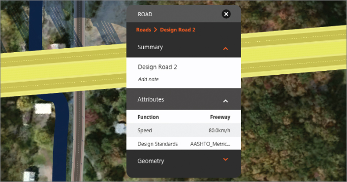
Figure 1.10 A selected road and its associated asset card
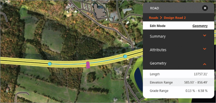
Figure 1.11 Specialized curve gizmos and a Geometry section on the Road asset card
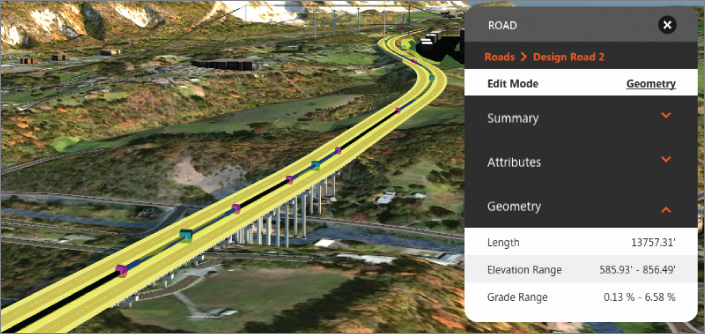
Figure 1.12 Specialized gizmos for vertical editing
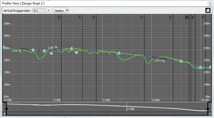
Figure 1.13 The Profile View panel