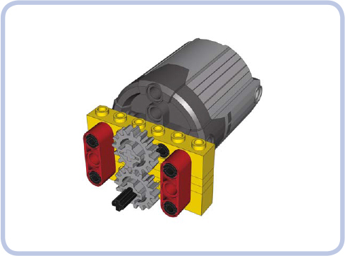
There was a time when Technic bricks alone could support and hold together almost any motorized mechanism. But eventually LEGO introduced stronger motors with enough torque to push even Technic brick connections apart. Having more torque at our disposal is an advantage in all aspects except one—it requires structural reinforcing, adding extra pieces whose primary purpose is to hold other pieces together (see Figure 12-1). A properly reinforced mechanism stays together regardless of its motor’s strength and how much load is applied to its output, even if the load stalls the motor.
This chapter explores how to find places in a structure where reinforcing is crucial; how to identify strong and weak LEGO pieces; and how to create casings, chassis, frames, and trusses to support your models.
In order to find where and how to reinforce our structures, we first have to understand why pieces come apart. When we house a mechanism inside a structure, it has an input, an output, and points of attachment to that structure; most often this means we have axles with gears that are housed in a structure’s pin holes, as shown in Figure 12-2. Whenever a mechanism works, it handles a load that exerts stress on its output and has to be overcome by the force applied to its input. For example, if our mechanism is a drive-train, the motor driving its input has to overcome the stress exerted by its wheels—the rolling resistance and friction. This means that there are basically two forces in our mechanism, one applied to its input and one applied to its output, and that they work against each other. In other words, the output resists the input, creating stress that is carried through every component between them.
Figure 12-1: The two red beams hold the yellow technic bricks together. Without these beams, the powerful PF Xl motor would push the lower brick away the moment it started running.
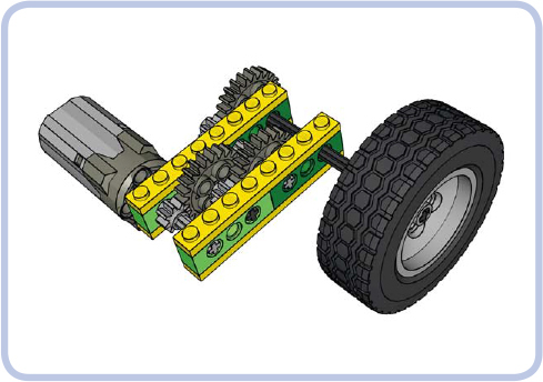
Figure 12-2: An example of a mechanism with a motor driving a wheel. The mechanism consists of six gears in three pairs on four axles, and it’s housed inside technic bricks held together by plates.
Let’s think of this mechanism as a chain, with input and output being the first and last links. The initial force applied to the input (the first link) will be transferred through the chain and will stop on the link of least resistance. If the structure around our mechanism is solid, all links will have more resistance than the mechanism’s output (the last link of the chain), and the mechanism will work as intended: Only the output will yield to the input. But if any link of our chain before the output has less resistance than the output, it will be dislocated and separated from the next link, thus breaking the chain and preventing the mechanism from working.
So let’s find the weak link in our chain. In our example from Figure 12-2, we have a motor connected to the axle, an axle connected to the 8-tooth gear, an 8-tooth gear connected to the 24-tooth gear, and so on, all the way to the output and the wheel.
Most of the axle pairs (or other connections) in this chain are within a single LEGO brick. But the connection marked by red arrows in Figure 12-3 involves two 2×4 Technic bricks, meaning that when stress is applied, it can break apart (as shown in Figure 12-4). When deciding where to reinforce your model, look for the seams that could separate under stress.
Also note that a pair of gears that increases the gear ratio (the driver gear is bigger than the follower) is more likely to come apart than a pair that decreases the gear ratio (the driver gear is smaller than the follower). There is simply more force exerted on the follower gear when gearing up, and such a pair of gears is a good candidate for reinforcing.
Figure 12-5 shows one obvious way to reinforce our mechanism: We simply replace the two pairs of 1×4 bricks with two 1×8 bricks. On the upside, the weak seam is now gone, every link in our chain is solid, and we no longer need to use plates. Additionally, this solution adds no weight and takes up no extra space. The downside is that using long, solid bricks can be an invasive way of reinforcing, and building in this way is time-consuming and extremely inconvenient with complex gearing, as you’ll have to place all elements at the same time.
Figures 12-6 and 12-7 show another way we can reinforce our mechanism: by adding support beams. This increases the weight of the mechanism and takes more space, but it involves only minimal changes to the original structure. Note that structures like the one shown in Figure 12-7 have the downside of added friction because the yellow bricks are partially supported by the axles—building compact mechanisms can come with a cost.
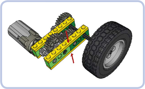
Figure 12-3: The critical con nection in the mechanism from Figure 13-2 is marked by a red arrow here. This connection lies between two separate bricks and is held together merely by the clutching force of two 1×8 plates (yellow); therefore, it can be broken easily.
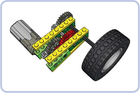
Figure 12-4: Without reinforcement, the weak link breaks apart the surrounding structure. The red gears are no longer meshed, and the mechanism fails.
The direction of a stressed gear’s displacement depends on its location and its direction of rotation. When one gear drives another that resists it, the driver gear pushes against the follower gear just as the follower gear pushes back. This principle, which you might remember from high school physics, is a case of Newton’s law of action and reaction, which states that forces are generated in equal and opposite pairs. Figure 12-8 shows a driver gear on top, rotating clockwise (as marked by the black arrow), and a follower gear on the bottom, being pushed down and to the side at the same time (as marked by the blue arrows).
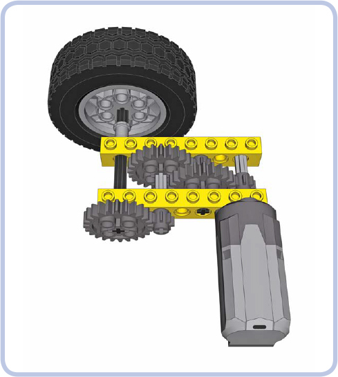
Figure 12-5: The two pairs of 1×4 bricks from our original structure have been replaced with two single, solid 1×8 bricks.
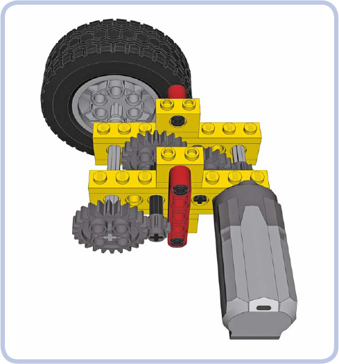
Figure 12-6: Vertical beams (red) are a popular means of reinforcement.
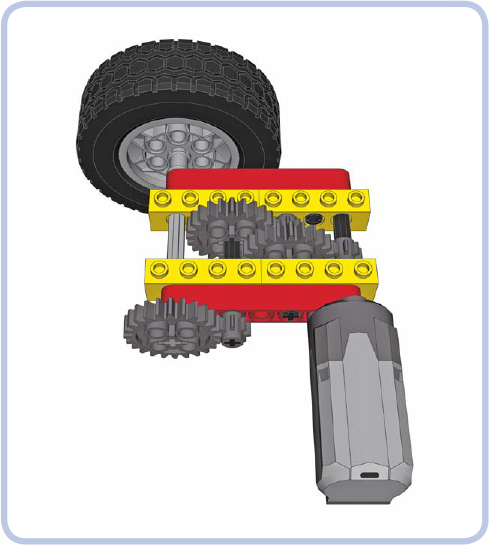
Figure 12-7: If vertical space is limited, horizontal beams (red) can sometimes be used. In this case, doing so requires using a few longer axles and moving the motor 1 stud away from the bricks. Note that in order to create a rigid connection, each of the bricks is attached to the beams at two points.
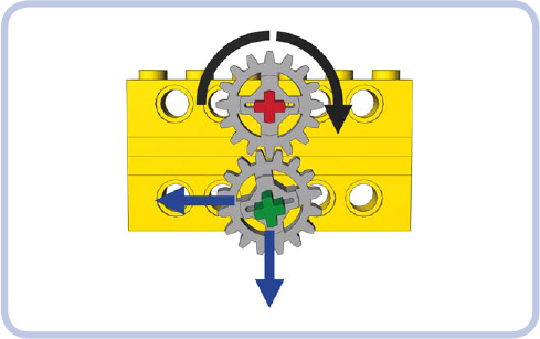
Figure 12-8: Directions of forces (blue) exerted by a driver gear (top) on the follower gear (bottom)
Now, if there were nothing holding the bricks in Figure 12-8 together, the follower gear would be pushed downward and to the left. The key to reinforcing properly is to limit displacement in both directions: Pieces that can’t be separated can still be rotated, displacing and misaligning important elements of our drivetrain.
This same principle applies when two gears are mated at a different angle, as shown in Figure 12-9. Note that the gears in this figure can’t come apart because their axles are both housed in a single L-shaped beam.
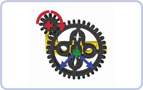
Figure 12-9: The directions of force exerted on the follower gear, which is located below and to the side of the driver gear
Now that we know how to find weak links in our mechanisms, let’s look at some examples of reinforcing. Figures 12-10 to 12-14 show reinforcing done poorly and done properly.
As you can see, reinforcing gears is about making sure the axles are securely supported. But since axles can be long and prone to bending, there are two rules to follow here:
 The axle should be supported at least at two points.
The axle should be supported as close to the gears on it as possible, preferably from both sides of the gears.
Figure 12-15 illustrates the first rule, and Figure 12-16 illustrates the second rule. Axles are in fact much less rigid than beams or bricks, and they can bend, twist, or even slide through the gears when subjected to sufficient stress.
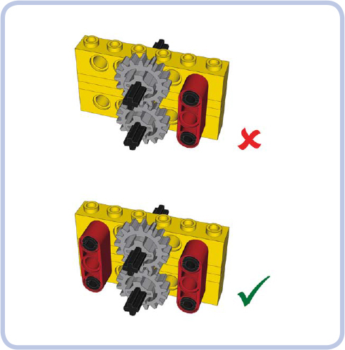
Figure 12-10: Holding one end of the bricks together doesn’t create a rigid connection, but holding both does.
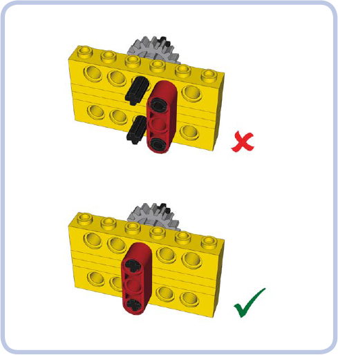
Figure 12-11: It’s possible to reduce the number of reinforcing pieces by aligning them to the meshed gears rather than pairing them.

Figure 12-12: The l-shaped beam alone is not enough to create a rigid connection because it has only one point of attachment to the upper brick.
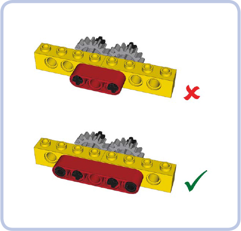
Figure 12-13: Beams that have only one point of attachment to adjacent bricks don’t create a rigid connection. At least two points of connection to each brick are needed.
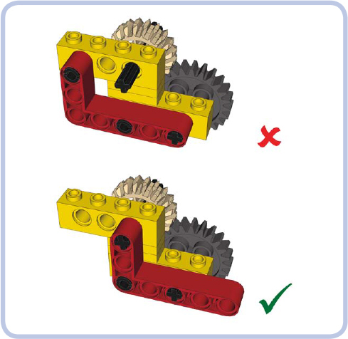
Figure 12-14: Plates help to create rigid connections. Use them as spacers between the points of connections of two bricks to prevent the bricks from oscillating.
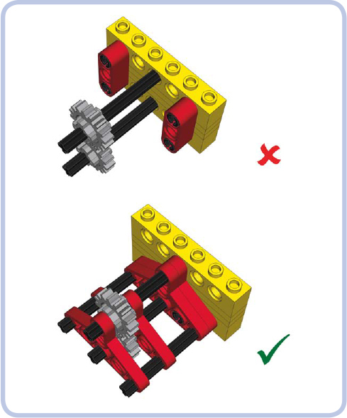
Figure 12-15: Both ends of the axles need to be reinforced to prevent the gears on them from coming apart.
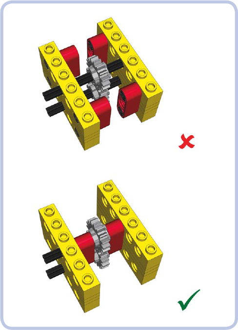
Figure 12-16: Empty space on the axles adjacent to the gears allows them to slide or enables the whole axle to bend. This empty space should be used for reinforcement.
Figure 12-17 shows a permanently twisted axle. Note that the longer the axle, the more easily it gets twisted— that’s why it’s always a good idea to swap a single long axle for a few shorter ones connected with axle joiners. Another good idea is to add substantial gear reduction near the output so that only a small portion of the drivetrain is subjected to high torque.
Reinforcing perpendicular bevel gears is a more difficult task, as even a minimal displacement in structure disengages the gears. This is because their teeth come into contact over a small area. We need to make sure the gears are firmly kept in place. A number of LEGO studfull and studless pieces are designed specifically to reinforce perpendicular gears, as shown in Figures 12-18 to 12-20.
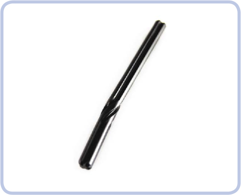
Figure 12-17: Axles are much more elastic than they might seem. This one has been twisted permanently by a PF Xl motor.
When you have no dedicated LEGO pieces to reinforce perpendicular gears, you can still use basic pieces to do so. Figures 12-21 and 12-22 show examples of this approach using studfull and studless pieces.
There are a few more rules of reinforcing worth keeping in mind:
Minimal reinforcement is the best reinforcement. Extra pieces add weight and take up space.
If a seam or joint can separate, it eventually will—and usually when you least expect it. (And Murphy’s law says that it will be deep inside your MOC where you can’t fix it!)
Real reinforcement doesn’t yield until pieces physically break.
When building, think about disassembly, too. A reinforcement that has to be cut to be taken apart will cost you pieces.
The last rule is no less important than the ones preceding it. It’s fairly easy to connect LEGO pieces in such a way that the resulting structure is impossible to disassemble without cutting some of the pieces. Figure 12-23 shows some examples. As you’ll see, you should take precautions when inserting axles—always make sure it’s possible to pull or push them out.
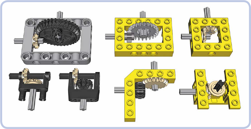
Figure 12-18: LEGO pieces for reinforcing perpendicular gears
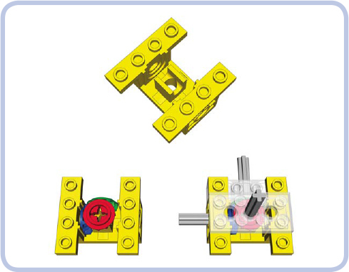
Figure 12-19: Piece #6585 is a particularly interesting brace that can reinforce both horizontal and vertical gears. Technic bricks and plates can be connected to it to support their axles.
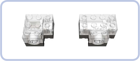
Figure 12-20: There are also so-called Technic gearboxes, which have special sturdy bevel gears enclosed. They are robust and can have axles inserted into them, but they are rare.
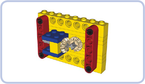
Figure 12-21: Perpendicular gears reinforced with bricks held together by beams. Note the use of 2×3 plates (blue) to hold the perpendicular brick.
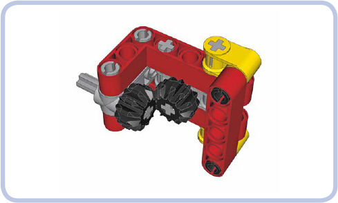
Figure 12-22: Perpendicular gears reinforced with l-shaped beams. Note that one end of the beams is held together by a vertical beam. This is because there are only axles on this end of the beams and the axles don’t hold the beams together. The other end of the beams has a connector with pins that hold the beams together with a force very unlikely to be overcome by gears.
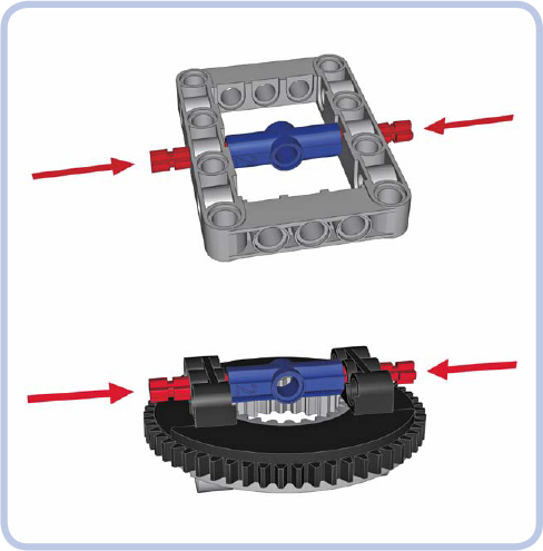
Figure 12-23: Dangerous structures: Once the axles marked by arrows are pushed in, these structures are impossible to take apart without cutting pieces.
Differentials are often subjected to high torque because there is usually no gear reduction between them and the wheels. To make things worse, they are usually meshed using perpendicular gears. It was only in 2009 that LEGO released pieces designed specifically to remedy this problem: studless frames. But studless frames aren’t very common and work only with the newest type of differential gear, as shown in Figures 12-24 and 12-25.
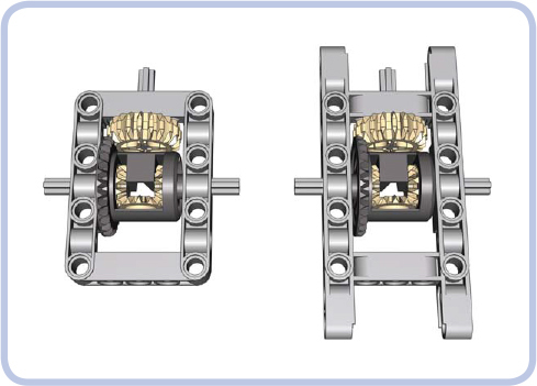
Figure 12-24: The studless frame comes in a regular (left) and an extended (right) variant. Both create a perfectly rigid reinforcement for the newest type of LEGO differential.
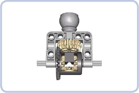
Figure 12-25: The larger part of the ball joint comes with an attached C-shaped frame, large enough to house the newest type of LEGO differential.
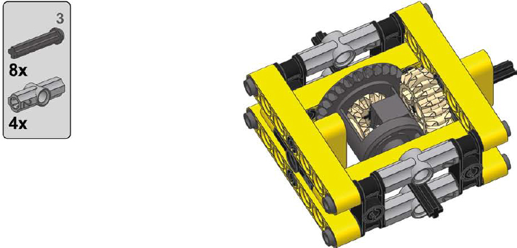
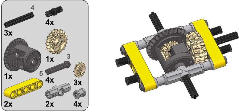
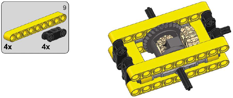
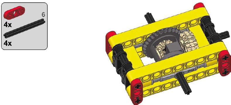
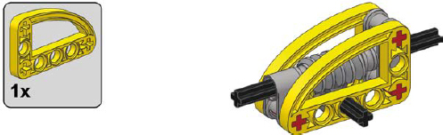
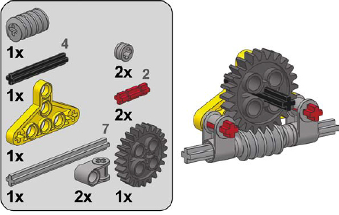
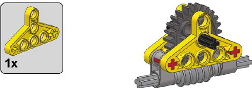
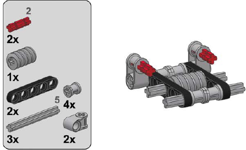
The following are examples of sturdy casings for all types of differentials, made of common pieces. They are inevitably inferior to studless frames because of their greater size and weight, but they are useful nonetheless.
1
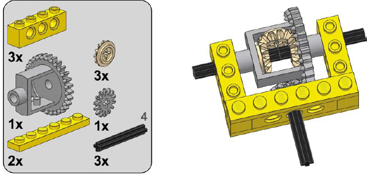
2
3
1
2
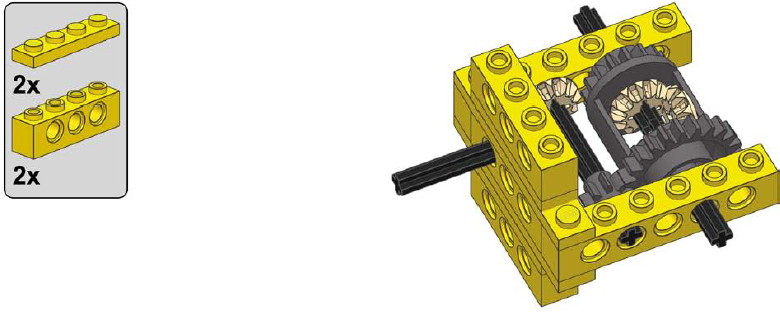
3
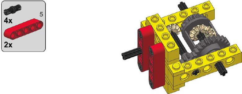
1
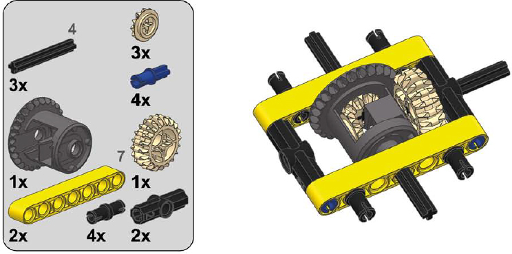
2
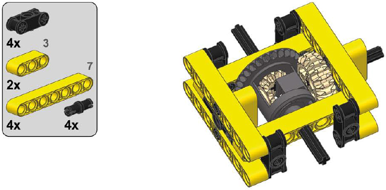
3
1
2
3
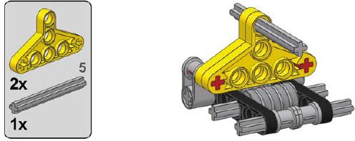
Because of their unique design, worm gears need particularly solid reinforcement. As Figure 12-26 shows, apart from pushing the follower gear away, worm gears have a strong tendency to slide along the axle they’re sitting on. This is a result of worm gears’ enlarged axle holes. This lateral force can be strong enough to make a worm gear drill through adjacent pieces if sufficiently high torque is applied to it for a prolonged time!
LEGO released special casings for worm gears, but they are relatively large and work only with 24-tooth follower gears, as shown in Figures 12-27 and 12-28.
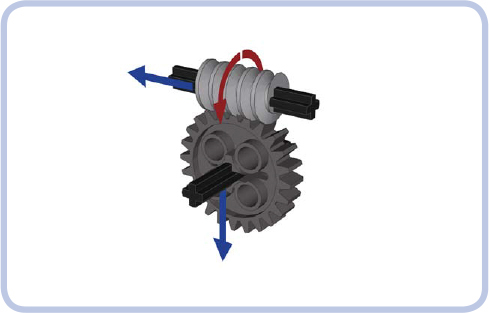
Figure 12-26: The directions of forces exerted by a worm gear. Unlike regular gears, a worm gear doesn’t push the follower gear to the side; instead, it pushes itself against the follower gear along its axle.
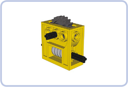
Figure 12-27: The LEGO casing for the worm gear is very sturdy and quite common, but it works only with a 24-tooth follower gear. It’s also better suited for studfull structures than for studless ones.
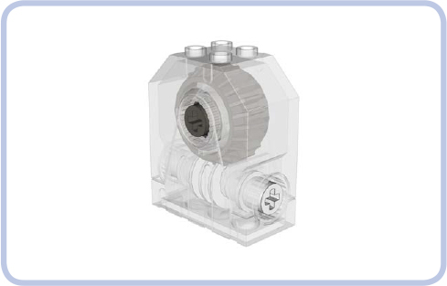
Figure 12-28: A gearbox with a worm gear and 24-tooth follower gear closed inside. It’s even sturdier than the regular casing, but it’s very rare.
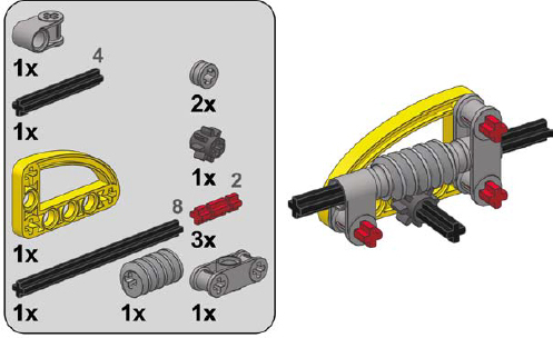
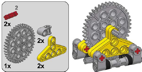
Thankfully, if you have neither a casing piece nor a gearbox piece, you can easily build your own. Three designs for worm gear casings (using various follower gears) are shown here.
1
2
1
2
1
2
3
Load-bearing structures are the “skeletons” within our models. You might think of these structures as the framing of a house, the pylons of a suspension bridge, the chassis of a car, or even the bones of the human body. They support a construction’s weight and maintain its rigidity, and they may have no other purpose beyond structural reinforcement.
A chassis is the type of a load-bearing structure most commonly used in vehicular models. A properly built chassis is sturdy enough to support the weight of the vehicle and rigid enough to maintain its shape as the vehicle negotiates obstacles and carries loads.
We’re going to focus on the most convenient and commonly used way to build a chassis: rails, also called stringers. Almost all LEGO Technic sets use this method.
Rails are longitudinal members that span most or the entire length of the vehicle. Since one rail is not rigid enough to support a vehicle’s weight, most body frames have two parallel rails, which are joined together with crossbeams so they act as one element. You can add other elements of the construction both in the gap between the rails and in the space around them.
Figure 12-29 shows a small, lightweight studless LEGO truck with two rails visible from the bottom. Note that elements are placed both on the sides of the rails (wheels, bumpers, side curtains) and between them (differential, piston engine).
Figures 12-30 and 12-31 show examples of simple studless and studfull rail/crossbeam configurations.
Configurations like these, which form a “skeleton” that supports other parts of the model, are called body frames. If you expect particularly large stress to be exerted on your model’s chassis, you can add another pair of rails above the first one and connect the two pairs. Figures 12-32 and 12-33 show examples of a studless and studfull body frame, and Figure 12-34 shows a studfull body frame at work in my Tow Truck 2 model.
The most common gap size between rails is between 3 and 6 studs. A gap this size is big enough for most of the heavy elements you may want to place in the center of your model, such as big motors and power supplies, but not so wide as to affect the frame’s rigidity.
Finally, we can build rails with more complex shapes to accommodate elements like pendular suspension components. Figure 12-35 shows examples of body frames with irregularly shaped rails.
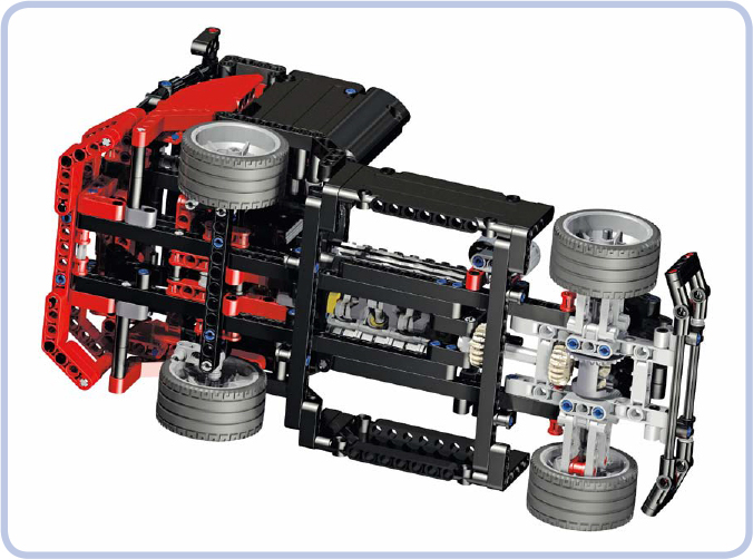
Figure 12-29: The 8041 set, a small racing truck, is a good example of a model built around two parallel rails.
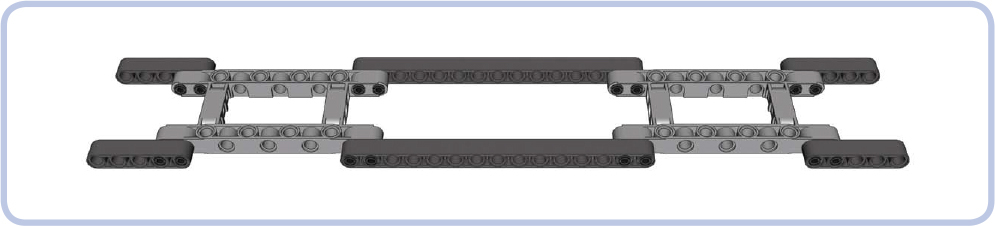
Figure 12-30: A simple combination of rails made of studless beams, with extended body frames working as crossbars. The frames provide space for differentials for front and rear axles, and there is plenty of space between the rails for a propulsion system or a power supply.
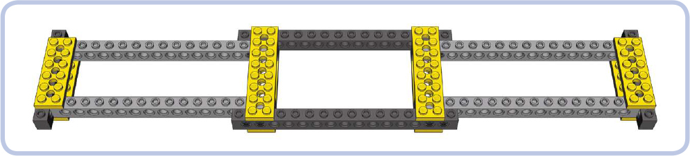
Figure 12-31: A simple studfull chassis combining bricks, pins, and plates
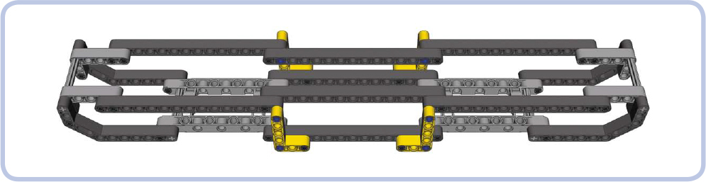
Figure 12-32: A studless body frame with two pairs of rails, one above the other. The upper pair is supported at the ends and in the middle. Studless frames work well with smaller, compact models where the ability to add many elements to the chassis is more important than its rigidity.
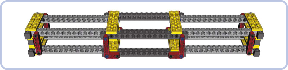
Figure 12-33: A typical studfull body frame, reinforced with vertical beams. This kind of frame works well for big, heavy models where rigidity is of primary importance.

Figure 12-34: My tow truck 2 model was very heavy and almost 0.8 m long. It was held together by a massive studfull body frame with two pairs of rails, rigid enough to allow the model to be lifted by hand without any problems. The boom of the truck had its own frame of four studless rails, with the extendable section placed in the middle. It was covered with a studfull shell, which not only made it look better but also improved its rigidity.
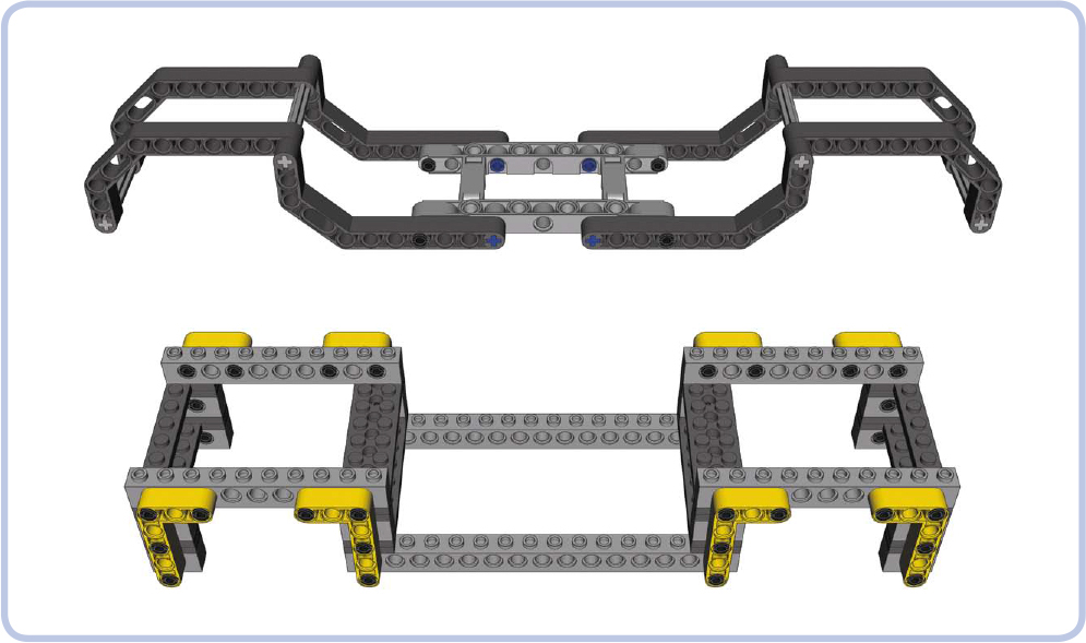
Figure 12-35: Examples of studless and studfull body frames with rails of complex shapes
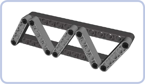
A truss is a particular type of load-bearing structure that consists of beams that form repeated triangles, as shown in Figure 12-36. The triangles are often identical in size, but they don’t have to be. The joints connecting these elements in a truss are often called nodes. Trusses are ubiq ui tous in the construction of buildings and machines—for example, tower cranes are built almost entirely with trusses. The advantage of trusses is that they can form large, lightweight, and very sturdy structures while using only a handful of basic pieces to build. Figure 12-37 shows a LEGO set that makes use of simple trusses.
Trusses can be divided into two categories: planar trusses, with all nodes within a single plane (like the truss in Figure 12-36), and space trusses, in which nodes extend in all three dimensions (like the truss in Figure 12-38). Space trusses are generally sturdier than planar trusses, and their simple construction allows for modular building. As Figure 12-38 shows, a simple space truss can actually be a combination of two or more planar trusses.
Just like any other load-bearing structures, trusses can be subjected to as many as four types of stress: compression, tension, bending, and torsion, as shown in Figure 12-39. It’s possible to build a truss that can resist all four types of stress, but such a truss is heavy, complex, and takes lots of pieces to build. A more “economical” approach is to choose the type of truss that can handle only the kinds of stress we expect it to experience.
There are more than 20 types of trusses in the world. However, their complex geometry makes many of them difficult to reproduce with LEGO pieces, so we’ll limit our discussion to three practical designs.
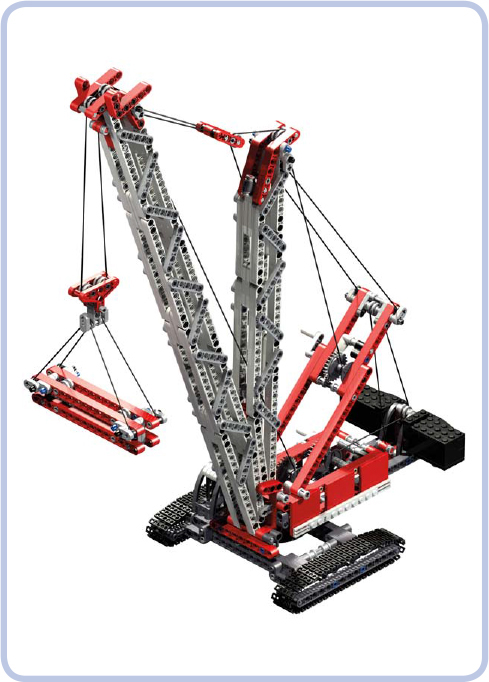
Figure 12-37: The 8288 crawler crane set comes with two booms (greyish in this image) made entirely of simple trusses.
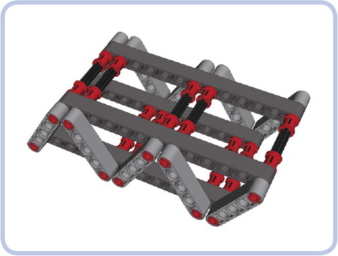
Figure 12-38: Two planar trusses, connected using axles and pins with bushes, create a basic space truss.
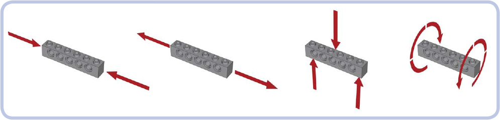
Figure 12-39: From left to right: compression, tension, bending, and torsion
The Brown truss uses an X-shaped reinforcement between two horizontal members. If there is only one reinforcement between these members, its slant beams must be connected in the middle. If there are multiple Xs, this connection is not needed, as shown in Figure 12-40.
The length and angle of beams in the Brown truss module can be adjusted as needed, but the module is strongest with crossbeams exactly perpendicular to each other. Our example above, with 12-stud-long horizontal beams and 13-stud-long crossbeams, is of a convenient size: The gap between the pin holes of the upper and lower horizontal beams is exactly 10 studs tall.
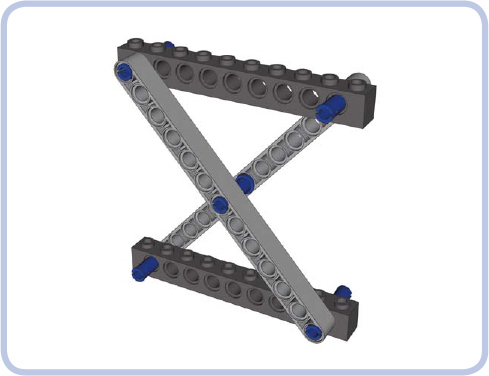
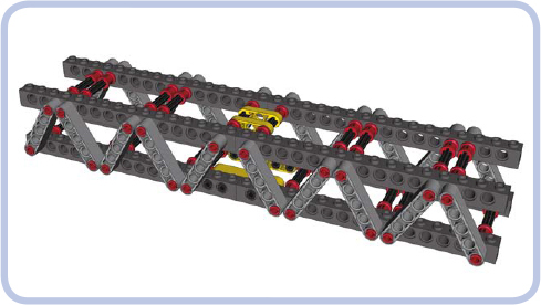
The basic building block of the Brown truss, the planar X, can be combined into planar trusses similar in construction to a scissor mechanism, as shown in Figure 12-40. A more interesting solution is to combine the planar X into a space truss, as shown in Figure 12-41. The space combination can also be used to build modules that can easily be stacked on top of one another, as shown in Figure 12-42.
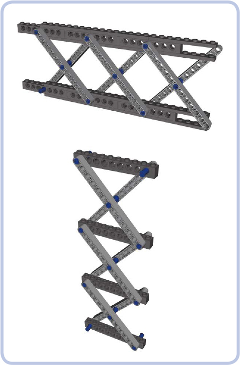
Figure 12-40: Planar combinations of the brown truss module
The Brown truss is resistant to compression and torsion. Its resistance to tension and bending depends on the strength of connections between its modules.
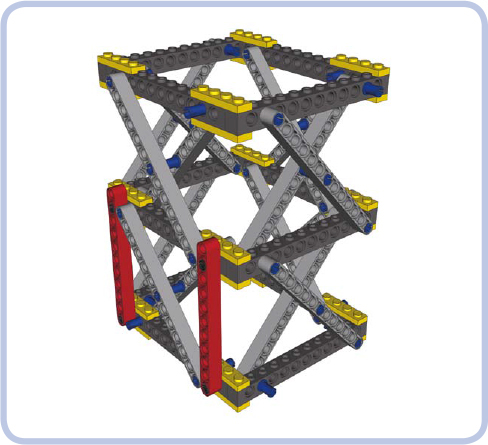
Figure 12-41: Space combination of the brown truss module. Note that vertical beams (red) can be added for further reinforcement.
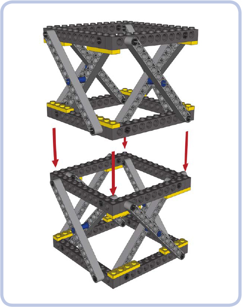
Figure 12-42: The brown module is shown here combined into space modules that can be stacked on top of one another. This arrangement allows you to easily adjust the height of the resulting structure.
The Warren truss combines two simple planar trusses. The length and angle of the slanted beams (light grey) can be adjusted as needed. The slanted beams also don’t have to be adjacent—small gaps between them are acceptable. The horizontal beams (dark grey) can be studless, as in Figure 12-38, or studfull, as shown above (in which case they can be further reinforced with plates).
The Warren truss is resistant to compression, tension, and bending. Torsion affects connections between its planar trusses and can lead to disintegration.
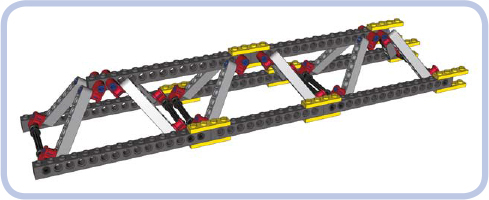
The triangular Warren truss, shown in Figures 12-43 and 12-44, combines two simple planar trusses to form the shape of a triangular prism. The truss has two lower beams but only one upper beam, which makes it weigh less than the regular Warren truss, though its construction requires additional connectors (red in the illustration and in Figures 12-43 and 12-44). This variant is nearly as robust as the regular Warren truss, except that its lower beams are subjected to more stress than the upper beam. Also, pressure on the upper beam can push the two lower beams apart unless they are connected (by perpendicular plates, for example).
The triangular Warren truss is resistant to compression, tension, and bending. With lower beams firmly connected by crossbeams, it is also considerably resistant to torsion.
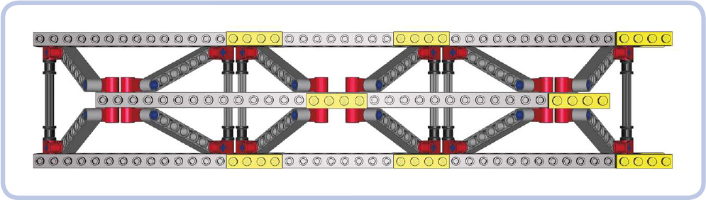
Figure 12-43: Top view of the triangular Warren truss
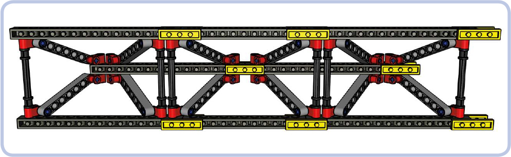
Figure 12-44: The bottom view of the triangular Warren truss shows that the lower beams (horizontal, top and bottom) are held together only from the inside of the truss. This means that they can be pushed apart by a sufficiently high load on the top beam (horizontal, middle).
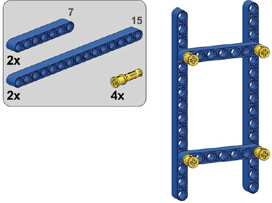
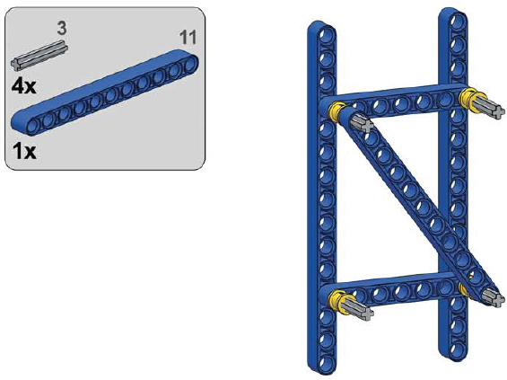
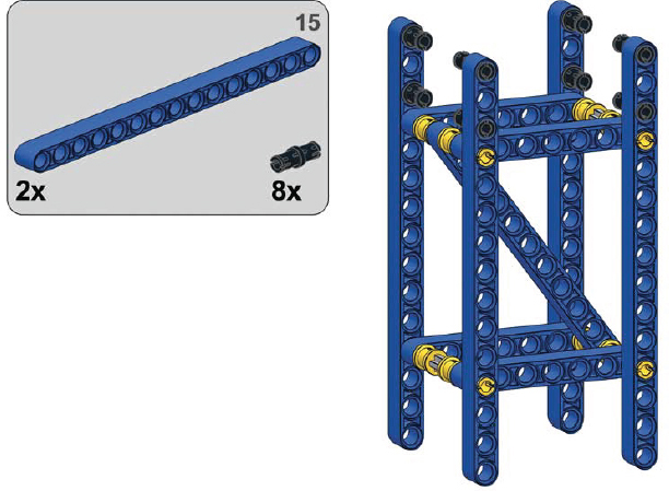
A very effective way of employing a triangular truss was demonstrated in the 42042 Crawler Crane set. It consists of identical, 15-stud-long modules connected together with beams and pins with a stop (see Figure 12-45). The modules, which are exceptionally simple, light, and strong, are similar to simplified Brown truss modules with alternating members instead of crossed members. The entire design is ingenious in its simplicity: There’s simply nothing redundant here! The resulting truss is resistant to everything except torsion.
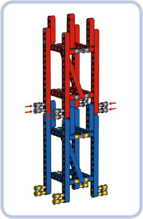
Figure 12-45: Two identical modules of simple triangular truss (red and blue) are joined by pushing in pins with bushes, as marked by red arrows.
1
2
3

4
5
A truss made of firmly connected Brown modules can withstand all types of stress. It is, however, complex and heavy, so you’ll want to use it only if it’s absolutely necessary. This section explores how to determine which truss will work best for various vehicles.
Let’s first consider a bus, which has a large gap between its front and rear axle. Its axles support it from the bottom, while its weight presses from the top on the middle of its chassis, as shown in Figure 12-46. This means that the chassis is subjected to bending. A regular Warren truss will easily handle that stress while also resisting the minor compression and tension that occur when the bus starts and stops.
An off-road truck, on the other hand, is less subject to bending due to its shorter length. But such a truck is designed to negotiate difficult obstacles, which will make its suspension work hard, making the wheels go up and down. It’s very likely that the front and rear axles of our truck will oscillate in opposite directions while traversing an obstacle, which will exert torsion on the chassis, as shown in Figure 12-47.
Figure 12-46: Forces exerted on the chassis of a bus. The chassis is primarily subjected to bending.
Figure 12-47: Forces exerted on the chassis of an off-road truck. The chassis is subjected primarily to torsion but also to bending.
We can use Brown modules in our truck’s chassis if we want it to be extremely sturdy, but we can also use the triangular Warren truss to save some weight and space. With its lower beams held together, the triangular Warren truss will handle both torsion and bending.
Our last example is a tower crane, which has several elements that could use reinforcing. We’ll see how different sections of the crane will benefit from using different kinds of trusses.
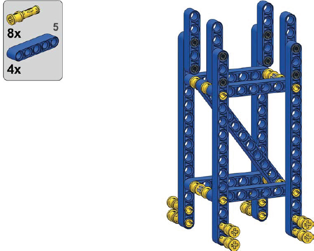
As Figure 12-48 shows, we can break our crane into four parts. First is the part that supports the entire crane, called the tower mast (yellow). As the weight of the crane rests on it, the tower mast is subjected to compression. Lifting loads also makes the crane tip a bit, so the structure is subject to some bending. Finally, the upper portion of the crane can rotate while the yellow truss remains fixed to the ground—this exerts torsion when rotation starts and stops.
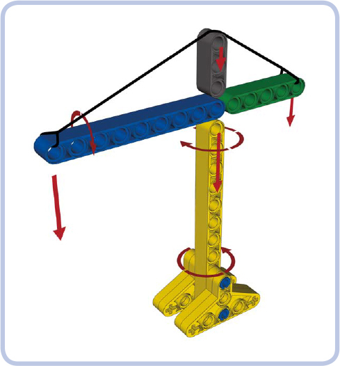
Figure 12-48: Forces exerted on various parts of a tower crane
So we know our yellow tower mast truss must withstand all types of stress except tension. A truss made of space Brown modules will be a good choice.
Our second truss (blue) is called the jib. It’s the part directly responsible for moving loads. As one end is fixed to the center of the crane, the other has loads suspended on it and is supported by a cable called the jib tie, which exerts some compression on it. As the crane rotates, the loads swing a little below the jib, exerting some torsion on it as well. Note that the jib is the second-largest part of the crane, and it can add a lot of weight. We want the jib to weigh as little as possible, so the triangular Warren truss will be a good choice here, resisting both compression and torsion while adding less weight than other options.
The third part (green) is called the counterjib. The counterjib is fixed to the center of the crane at one end and supports the crane’s counterweight at its other end. It is therefore subjected to bending, just like the jib, but to a smaller degree because of its shorter length. Its counterweight doesn’t swing during rotation, so it isn’t subjected to torsion. We can use the triangular Warren truss here as well, or we can instead choose the simpler regular Warren truss—the counterjib is so short that the difference in weight will be minimal.
Finally, the grey part, called the top mast, simply supports the cable that connects opposite tips of the jib and counterjib. The jib tie exerts compression on the top mast and slight bending on the counterjib, which we’ve already accounted for. The top mast is small and little stress is involved, so we can use a small section of the Warren truss; alternatively, we can give up on trusses and use any structure capable of supporting some weight put directly on top of it. Figure 12-49 shows an example of a real tower crane built the same way as our model.

Figure 12-49: A real tower crane at work. As you can see, its tower mast is built with a Brown truss, and its jib is built with a triangular Warren truss, just like in our model.
Although LEGO pieces are known for their lasting quality, they are prone to aging and wear. This means there are two things you should avoid when picking pieces for a tough job: aged pieces and physically worn pieces.
It’s safe to assume that LEGO pieces fully maintain their quality for at least 5 to 10 years, unless damaged. As your collection ages, or is supplemented with older pieces and garage sale treasures, you should carefully select the pieces that will handle high stress. The easiest way to determine a piece’s age is to keep a few new pieces for comparison. LEGO pieces, particularly white and grey pieces, yellow over time. Figures 12-50 to 12-52 show the difference.
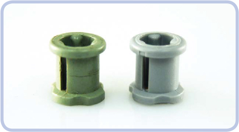
Figure 12-50: A bush: roughly 20 years old (left) and 1 year old (right). Note the crack in the old bush’s side; under torque, this crack will soon lead to the bush’s disintegration.
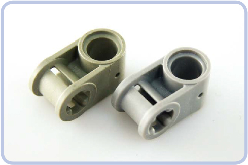
Figure 12-51: A connector: old (left) and new (right). Even though the old piece is free from damage or visible wear, the difference is obvious.
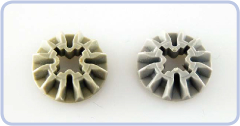
Figure 12-52: Two gears of the same type made roughly 10 years apart
Pieces that are physically worn aren’t too difficult to spot. The wear can vary from very subtle—negligible for our purposes—to obvious damage. You should look for wear on the surfaces that contact other pieces, such as the teeth of gears or the area around the pin hole in a brick. Wear occurs more often on pieces that are subjected to high stress, such as knobs, small gears that are crucial for high gear reduction, or various pieces that work with worm gears. Figures 12-53 to 12-55 show typical examples of wear.
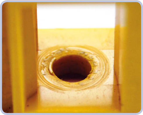
Figure 12-53: A close-up view showing the inside of a LEGO casing for a worm gear. Here, a worm gear has partially drilled into one of the casing sides.
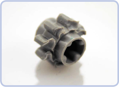
Figure 12-54: This gear’s teeth were ground away when it was misaligned to a larger, stronger gear. While the piece itself is new and most of it remains intact, this kind of wear makes the gear unusable.
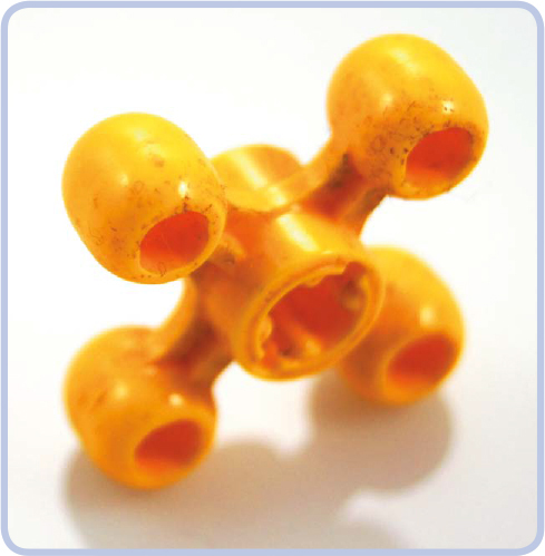
Figure 12-55: This visibly worn knob has polished edges where the material has been rubbed away. Knobs transfer high torque over very small areas of contact, resulting in intense wear. Worn knobs produce a distinctive squeaking when working under stress.
Finally, note that differently colored pieces actually have different properties. The exact variations are difficult to measure, but I have observed that red pieces are particularly weak while yellow pieces are particularly strong. The difference isn’t big, but it can manifest when pieces are subjected to prolonged stress.