User-configurable data can be used to control the firmware behavior with the same firmware code. The configuration data is designed to be updatable and mutated by the end user, whereas the firmware code is typically only editable by the platform manufacturer. As such, the protection of configuration data is different from the protection of the firmware code.
A UEFI variable is a way to store the UEFI firmware configuration. Let’s take UEFI variables as an example to describe the different protection mechanisms. These mechanisms can be used for alternate implementation choices to implement the firmware configuration data.
UEFI Variables
UEFI Variable Protection Mechanisms
Mechanism | Resist Software Attack | Resist Hardware Attack |
|---|---|---|
Integrity protection | Variable authentication Trusted Execution Environment Variable Lock Variable Sanity Check | Variable with RPMB Variable with RPMC Variable with TPM storage |
Availability protection | Variable quota management Flash wear-out protection | Variable atomicity Fault-tolerant write (FTW) |
Confidentiality protection | User Key Encrypted Variable | Platform Key Encrypted Variable User Key Encrypted Variable |
Integrity Protection
Variable Authentication
The purpose of variable authentication is to ensure the entity that calls the SetVariable() API to update the UEFI variable has the authority to update the variable. According to the UEFI specification, the caller needs to provide the updated variable with the signed certificate in order to update an authenticated variable.
- 1)
Count-based authenticated variable, if the EFI_VARIABLE_AUTHENTICATED_WRITE_ACCESS attribute is set (this is deprecated)
- 2)
Time-based authenticated variable, if the EFI_VARIABLE_TIME_BASED_AUTHENTICATED_WRITE_ACCESS attribute is set (currently used)
- 3)
Extensible authenticated variable (time based or nonce based), if the EFI_VARIABLE_ENHANCED_AUTHENTICATED_WRITE_ACCESS attribute is set (new)
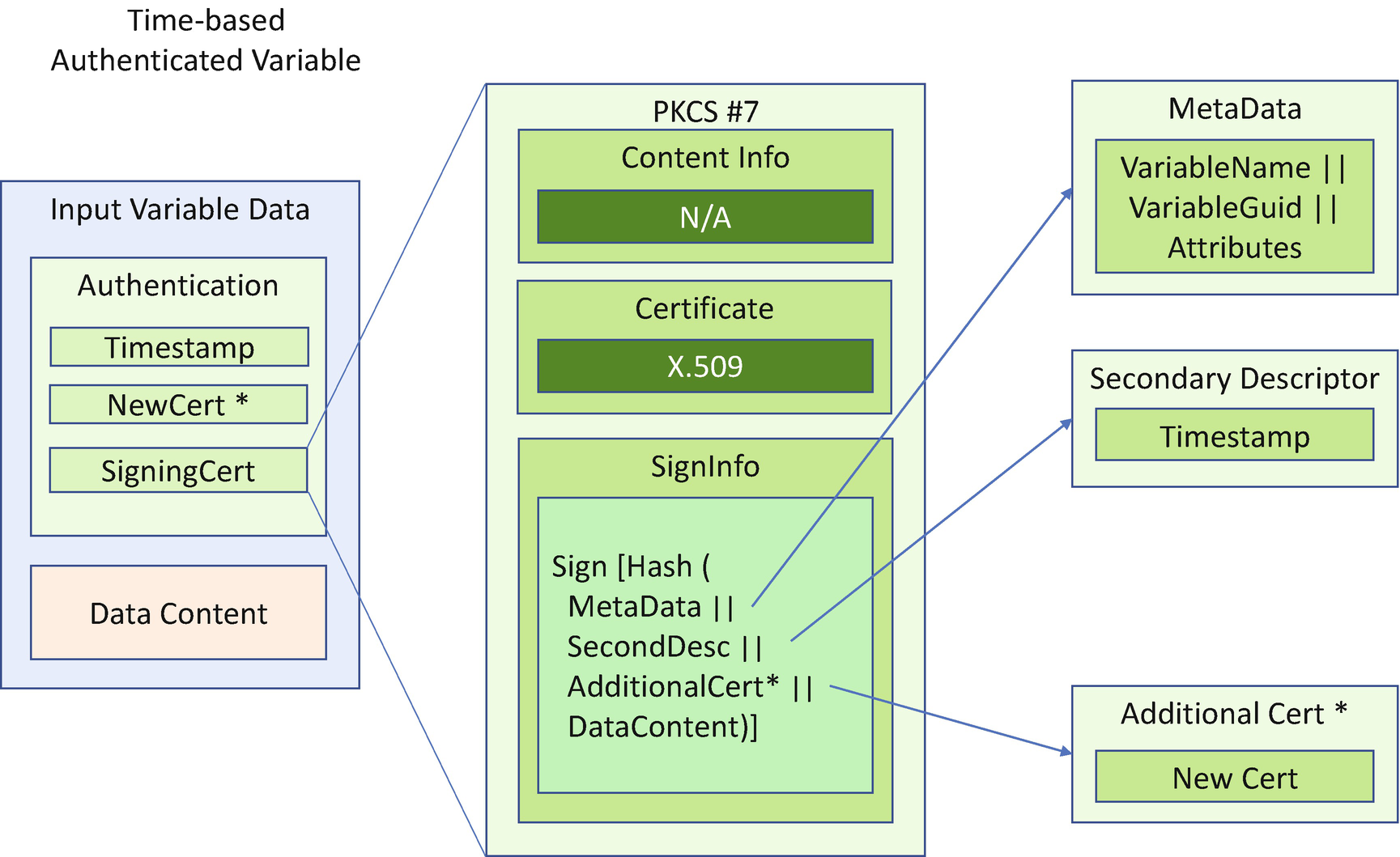
Authenticated Variable Input Format (Time Based)
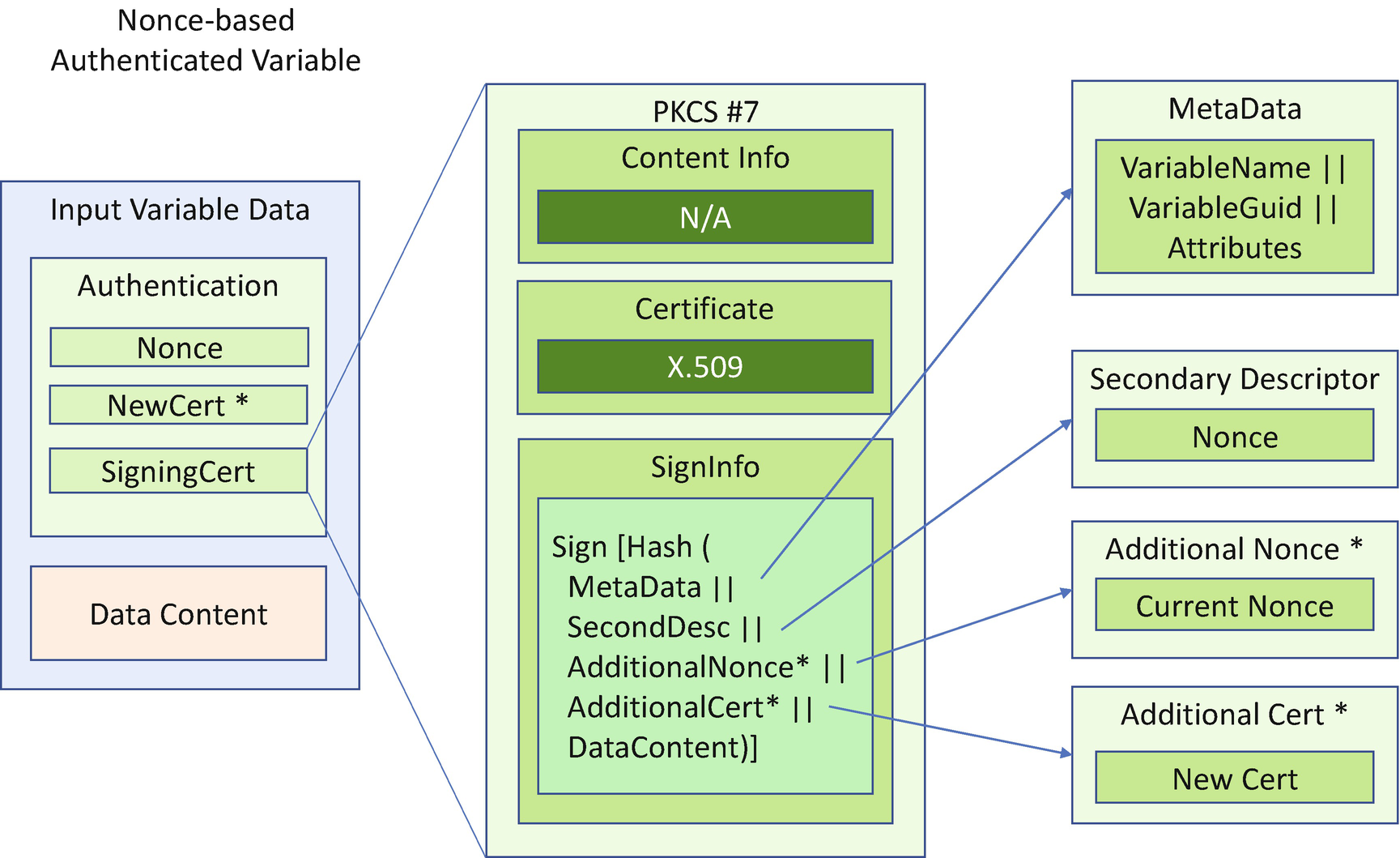
Authenticated Variable Input Format (Nonce Based)
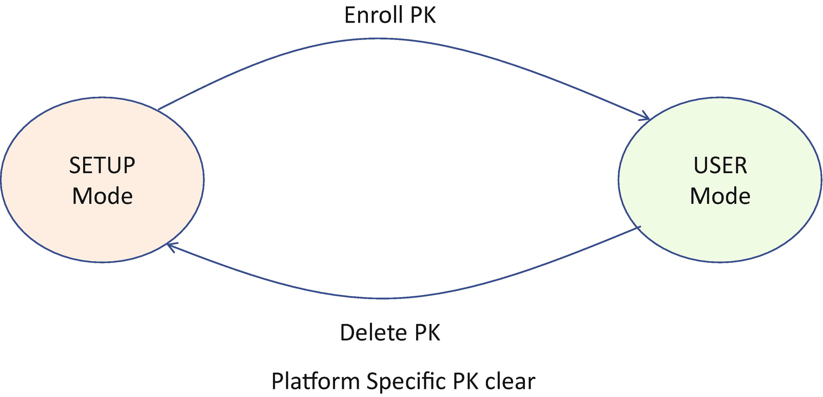
UEFI Secure Boot Setup Mode vs. User Mode

UEFI2.5 Secure Boot Modes (Source: UEFI Specification)
Deployed mode is an extension for user mode. Deployed mode is the most secure mode. By design, both user mode and audit mode support unauthenticated transitions to Deployed Mode. However, to move from deployed mode to any other mode requires a secure platform-specific method, or deleting the PK, which is authenticated.
- 1)
Standard secure boot mode: The default mode to follow the UEFI specification
- 2)Custom secure boot mode: Allows more flexibility as specified in the following:
PK variable update need NOT be signed by an old PK.
KEK variable update need NOT be signed by a PK.
Image signature database (db/dbx), timestamp database (dbt), and recovery database (dbr) update need NOT be signed by PK or KEK.
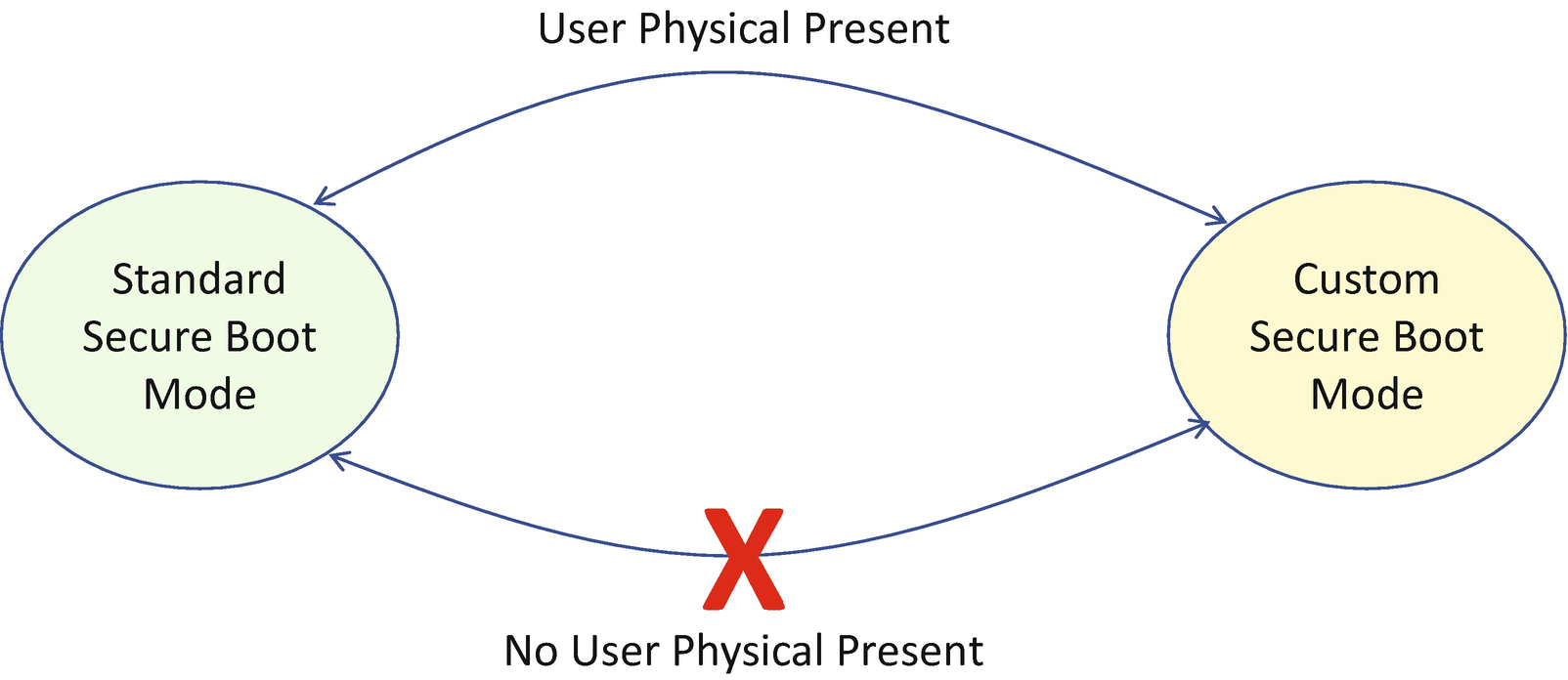
Standard Secure Boot Mode vs. Custom Secure Boot Mode
The switch between standard mode and custom mode needs user physical presence, as we discussed in Chapter 10. There must be a platform-specific way to detect if a physical user is present in order to perform such an action.
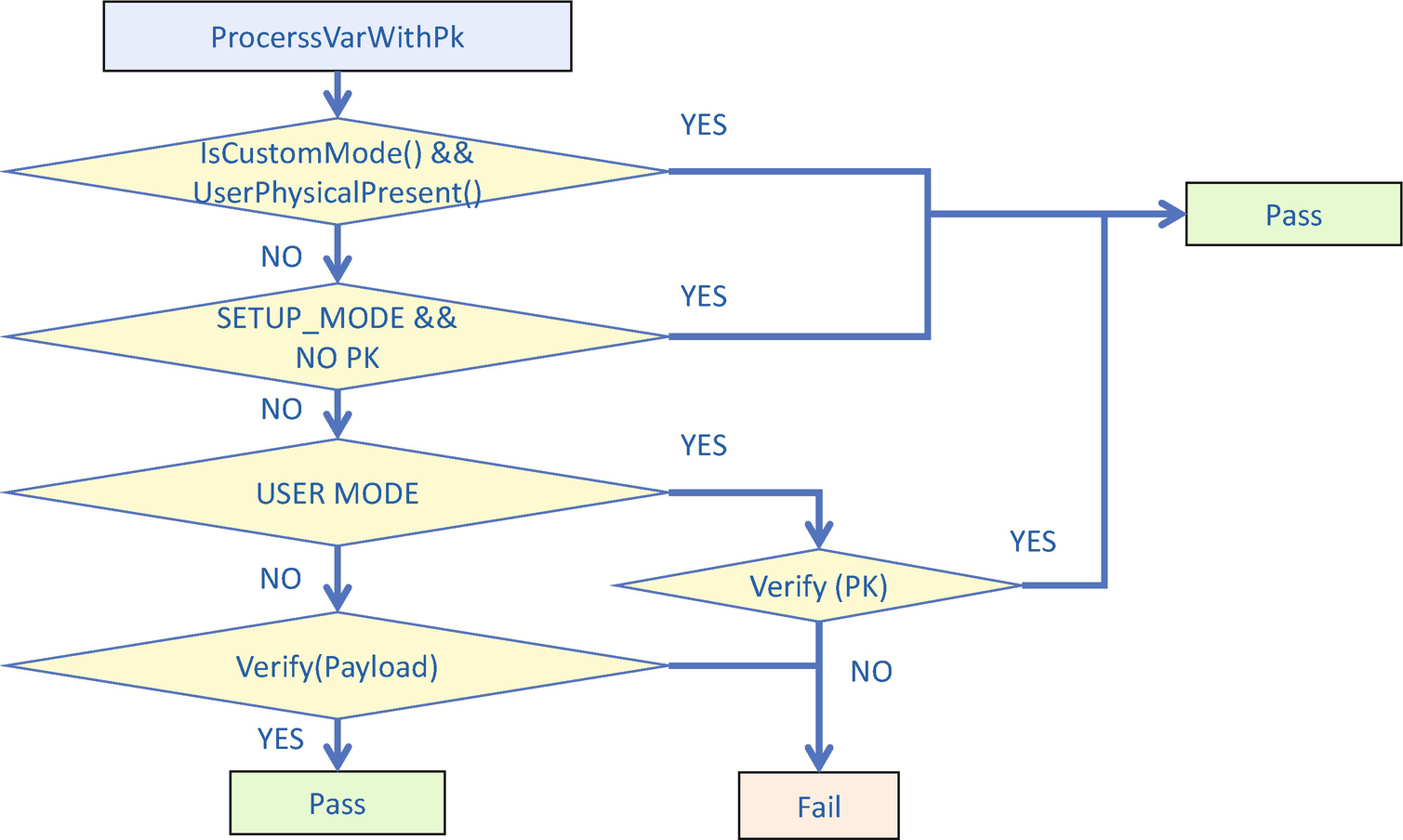
Variable Authentication Flow – ProcessVarWithPk

Variable Authentication Flow – ProcessVarWithKek

Variable Authentication Flow – ProcessVariable
Trusted Execution Environment
Similar to firmware image signing verification, the variable authentication and update requires a trusted execution environment. That achieves the non-bypassability of the capability.

TEE-Based Auth Variable Update
Variable Lock
In addition to user configuration variables, the system may need to record the current platform data at runtime. For example, it can include the memory initialization training data. Memory training is time-consuming, and the training data is the same across a warm reset or S3 resume. As such, there is no need to train the memory again. We may save the training data to the non-volatile storage and restore the configuration directly after a warm reset or during a S3 resume.
How can we can make sure the configuration data is not modified by another entity? The easiest way is just to lock the variable and make it unchangeable at some point in time.
Before the EndOfDxe event, the EDKII_VARIABLE_LOCK_PROTOCOL.RequestToLock() API is used to submit a Variable Lock request.
This lock request itself is volatile. That means RequestToLock() must be called each boot.
After the EndOfDxe event, the RequestToLock() API is closed.
Before the EndOfDxe event, Variable Lock does not take effect because only the OEM BIOS code is executed and trusted.
After the EndOfDxe event, Variable Lock takes effect in the DXE or OS runtime phase because the third-party code is not trusted. A locked variable cannot be deleted or updated. A locked variable cannot be created if it has not existed before.
Variable Lock does not have any effect in SMM because SMM is constructed by the OEM BIOS and there is no non-platform code in SMM. Inside SMM, the variable can still be updated.

Variable Features in Each Phase
RO means read-only.
RW means read/write.
RWC means read/write, with reclaim feature.
RWL means read/write, with lock feature.
The UEFI specification also defined other attributes such as RUNTIME (RT). Variables with the RT attribute are not accessible after the Exit Boot Service event.
Variable Sanity Check
A platform may define a setup variable that can be used by the UEFI Human Interface Infrastructure (HII) so that users can control the platform settings by updating a setup User Interface (UI). For example, a user can configure a SATA controller to be in IDE mode or AHCI mode or RAID mode. A setup variable field SataMode is used. 1 means IDE mode, 5 means AHCI mode, and 6 means RAID mode. Other values, such as 0, 2, 3, 4, or 7, are considered as invalid input.
The problem is that there is no way to check if some variable fields are valid and reject invalid variable updates. In the preceding example, when the code calls SetVariable() to update a setup variable, we hope the variable driver can check SataMode to see if the setting is valid (1, 5, or 6) and reject the variable update if the setting is invalid.
In order to resolve this problem, EDK II introduced “Variable Check” – the capability of checking variable contents based on a predefined policy.
Attributes: UEFI-defined variable attributes (BS, RT, NV, etc.)
Property: Non–UEFI-defined variable attributes (READ_ONLY)
MinSize: The minimum size of the variable data
MaxSize: The maximum size of the variable data
- 1)
HII-based checker
The UEFI specification’s HII section defines HII opcodes that allow the setting UI to be linked with UEFI variable storage. Some other setup options go through the HII_CONFIG_ACCESS_PROTOCOL. They could link to a variable or some other storages. If a variable is associated with a setup option, we can use data in HII IFR opcode to check the legal configuration of variable content. For example, the variable mapped to the ONE_OF_OP, NUMERIC_OP, ORDERED_LIST_OP, or CHECKBOX_OP must be in a predefined range.
Static HII data: HII data built inside of the firmware volume. The EDK II build tool generates HII information into an FFS raw section (see Figure 11-11) or a UEFI-specific PE/COFF resource. The typical usage is setup configuration data. The information can be retrieved even if some special setup data is not installed into the HII database due to the current hardware configuration.

HII Build Time Info
Dynamic HII data: HII data exposed by the HII_DATABASE_PROTOCOL. This is the UEFI-defined way to get HII data from the HII database. The platform code or third-party option ROM may construct HII data dynamically from C code. All HII data is exposed by the HII_DATABASE_PROTOCOL.
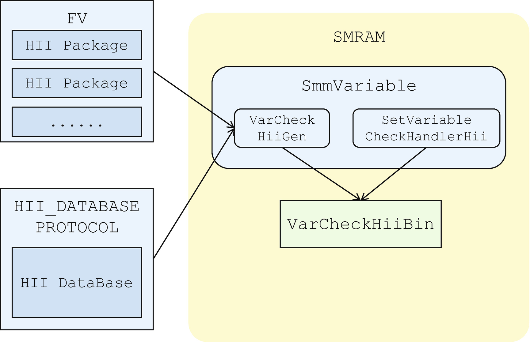
Variable Check HII
- 2)
PCD-based checker
@ValidList: Variable data must be in the list.
@ValidRange: Variable data must be in the range.
Therefore, we have a way to check if the PCD-mapped variable is legal.
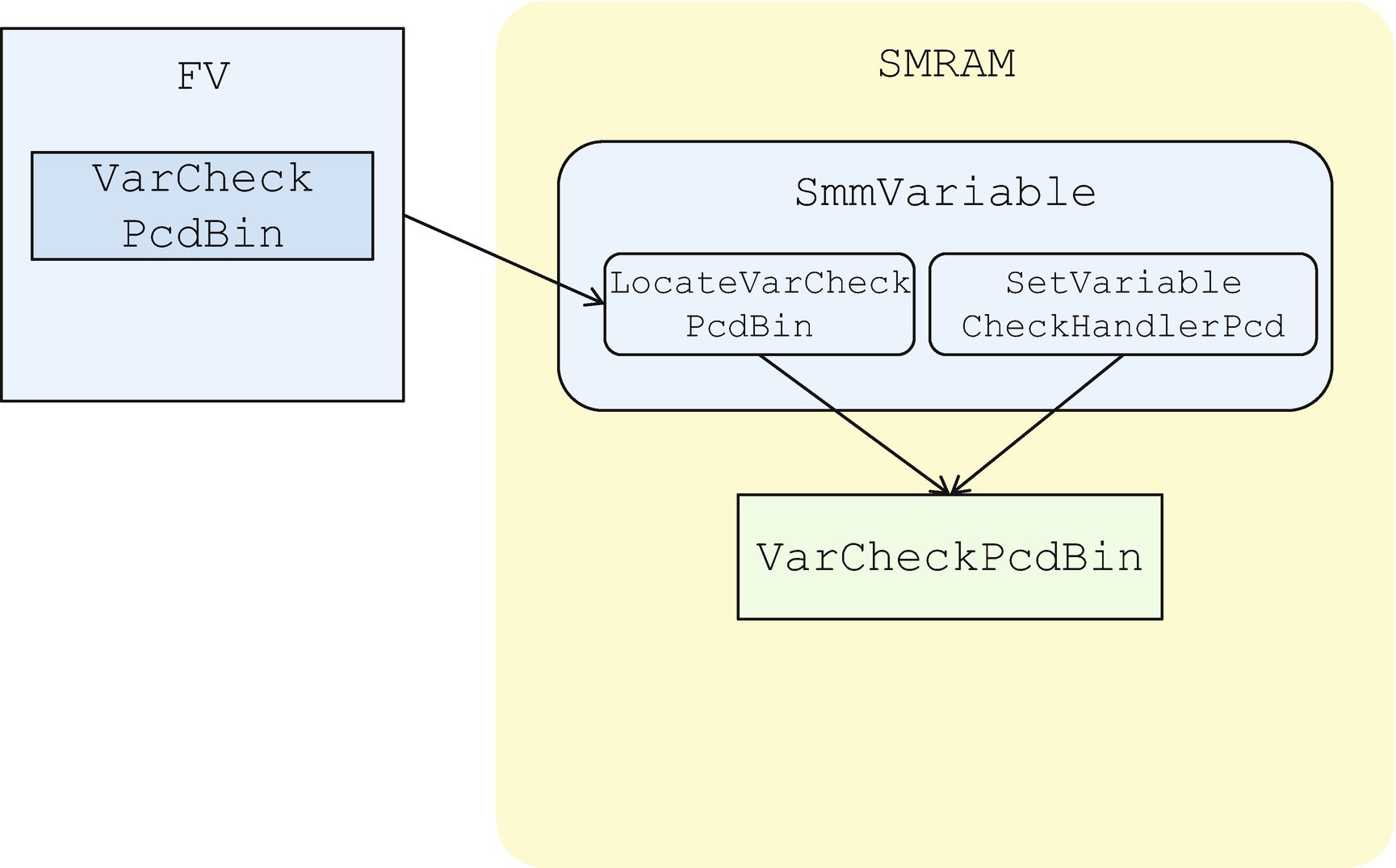
Variable Check PCD
PCDs include the offset in the variable but not the variable’s size. We can only check if a variable is too small, but we cannot determine if a variable is too large. This is a known limitation of VarCheckPcd.
The EDK II VarCheckPcd handler uses a simple policy for @ValidList and @ValidRange. A known limitation is that PCD’s @Expression validity check is unsupported, since this needs expression parser support. The implementation might be too complicated.
The variable checker only checks the variable format in SetVariable() API. It does not check variable format in GetVariable() API, assuming that if variable data is checked on Set, it must be correct on Get.
This assumption is true if our adversary is a software attacker, but it is not true for the hardware attacker, which we will discuss in the following section.
Variable with Replay Protected Memory Block (RPMB)
Some storage devices support Replay Protected Memory Block (RPMB) capability, such as those conforming to the Non-Volatile Memory Express (NVMe), Embedded Multimedia Card (eMMC), or Universal Flash Storage (UFS) specifications. In such devices, there is a special partition named the RPMB partition. Writing to the RPMB partition requires special hardware authentication. Reading from a RPMB partition returns the signature of the data for authentication.
A RPMB key only known by the device and the host Trusted Execution Environment (TEE) for write protection.
A monotonic counter to resist replay attack
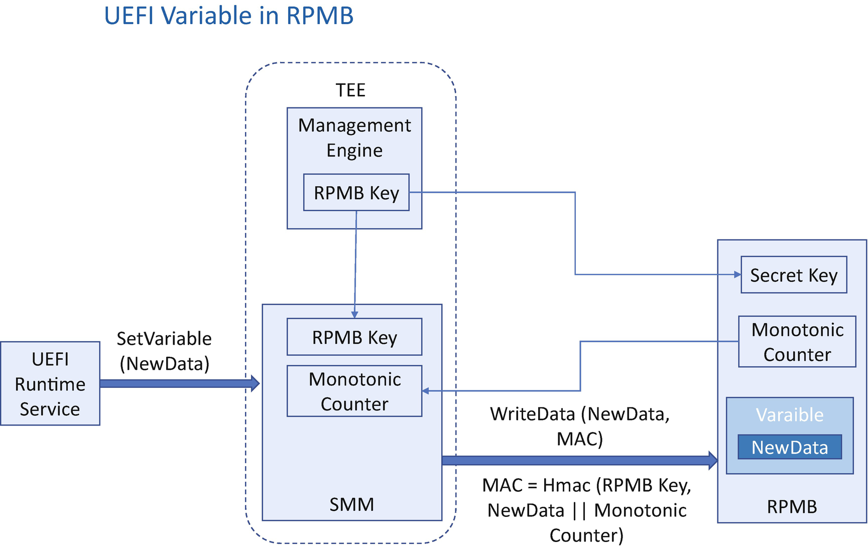
Variable with RPMB
When writing, the host TEE needs to read the device monotonic counter, calculate the hash-based message authentication code – HMAC(RPMB key, data || monotonic counter) – and send data, monotonic counter, and HMAC to the device. The device will check if the monotonic counter is the same as the current one. If they are the same, then the device will verify the HMAC value. Only after the HMAC verification passes the device writes the data into the RPMB area and increases the monotonic counter.
When reading, the host TEE generates a random value and sends the read request to the device. The device reads out the data, calculates the HMAC(RPMB key, data || random value), and sends the data, random value, and HMAC to the host. After the host gets the data, the host will check whether the random value is the same as the current one. If they are the same, then the host will verify the HMAC value. Only after the HMAC verification passes the host can then make sure the data is from the real RPMB device.
One RPMB-capable device may have multiple RPMB partitions. Each RPMB partition can only have one owner. If we save UEFI variables into a RPMB partition, the BIOS is the owner for this partition. The SMM and Management Engine (ME) can be used as a TEE. In the manufacturing phase, the ME can generate a unique RPMB key and provision it to the RPMB device. During runtime, the SMM variable driver can get the RPMB key from the ME and get the monotonic counter from the RPMB device. When a UEFI runtime service is used to set a new variable, it sends a request to the SMM variable driver. The SMM variable driver then calculates the HMAC and sends both data and HMAC to the RPMB device. Then the RPMB device verifies the HMAC and writes the data onto the RPMB storage area.
The hardware attack to the variable won’t succeed since the attacker does not know the RPMB key. As such, they cannot create a HMAC for the new variable data.
The replay attack can also be mitigated based upon the fact that the HMAC includes a monotonic counter. Writing old data will be rejected because the counter in the old HMAC does not match the current one.
Variable with Replay Protected Monotonic Counter (RPMC)
RPMB requires special storage devices. If a system does not have such a RPMB-capable device but only has a traditional SSD and SPI flash, then the enhanced SPI flash with Replay Protected Monotonic Counter (RPMC) capability can be used.
The RPMC device has a monotonic counter. A unique RPMC key is required to increment the monotonic counter. In the manufacturing phase, each RPMC device has a unique RPMC key generated and programmed into the device’s one-time programmable (OTP) area. The RPMC key is only known by the host TEE. As such, the host TEE can increment the monotonic counter with the MAC-based authentication.
RPMC SPI devices have no flash write authentication capability. The host TEE can access the RPMC-capable SPI device like a normal SPI device. The value of the RPMC SPI device that it provides a monotonic counter which can help to resist the replay attack.

Variable with RPMC
During runtime, the SMM variable driver can get the platform key from the ME for variable data MAC and get the RPMC HMAC key from the ME to increment the monotonic counter of the RPMC device. The SMM variable driver also gets the monotonic counter from the RPMC device. When the SMM variable driver gets a request to update a variable, it uses the platform key and the monotonic counter to create a HMAC for the variable region – HMAC(platform key, Variable1 || Variable2 || … || VariableN || Monotonic Counter), with VariableX = Name || Guid || Attributes || DataSize || Data. Then the SMM variable driver saves both the data and the HMAC to the flash device. This HMAC is saved as the variable metadata. Because the HMAC is calculated with the platform key, the attacker cannot tamper with the HMAC. Finally, the SMM variable driver sends the IncrementCounter() command to the RPMC device with HMAC(RPMC Hmac Key, monotonic counter). On the next boot, the variable driver reads all of the variable data and the metadata. The variable driver calculates the HMAC with the platform key, all variable data, and the monotonic counter. Then the variable driver compares the calculated HMAC with the variable metadata. If they are the same, then the variable region is good. Otherwise, the variable region has been updated by an unauthorized entity. After such a mismatch is found, the recovery process is triggered.
Hardware writes to the variable region will succeed. However, this attack will be detected on the next boot based upon the variable’s metadata and based upon the fact that the attacker does not have the platform key and cannot create the valid HMAC. Once the attack is detected, the system firmware must trigger the variable recovery process. The firmware settings for recovery have been discussed in Chapter 5.
The replay attack can also be mitigated based upon the fact that the HMAC includes a monotonic counter. Writing the same old data will be rejected because the counter in the old HMAC does not match the current one. Also, the attacker cannot send the command to increment the RPMC monotonic counter, based upon the fact that the attacker does not have the RPMC root key and RPMC HMAC key.
Variable with RPMB vs. RPMC
Property | RPMB | RPMC |
|---|---|---|
Flash device | NVMe/eMMC/UFS. | SPI. |
Monotonic counter | Stored in the RPMB device. Counter increased for every write. | Stored in the RPMC device. Counter increased for every write. |
Secret key | RPMB key: One time non-volatile. Provisioned into RPMB during manufacture. Host TEE gets the key from the ME during runtime. | RPMC root key: One time non-volatile. Provisioned into RPMC during manufacture. RPMC HMAC key: Generated during boot time. Host TEE gets the key from the ME during runtime. Platform key: One time non-volatile. Host TEE gets the key from the ME during runtime. |
Content storage | In RPMB device. | In SPI flash device. |
Security property | Integrity, confidentiality, availability. | Integrity. |
Protection (write authentication) | Done by the RPMB device. Write MAC is calculated by the host TEE and verified by RPMB. | No. RPMC SPI flash does not have capability for write authentication. MAC is calculated by the host TEE and stored on the flash device. |
Detection (read verification) | Done by the host TEE. Read MAC is calculated by the RPMB device and verified by the host TEE. | Done by the host TEE. MAC is calculated by the host TEE at write operation and verified once during initialization in next boot. |
Recovery | Not required. | Required, if the hardware modification is detected on the next boot. |
Variable with TPM Storage

Variable with TPM NV Storage
The alternative is to record a hash of the variable data. As such, the unauthorized modification can be detected later if the attacker updated the variable region directly.
The TPM NV storage can be used to save UEFI variable data. It can also be used to save UEFI variable–independent data. As such, the caller needs to use the TPM interface to access the variable data, instead of the UEFI interface. If the TPM NV storage stores the hash, the variable data can be in the UEFI variable or other storage such as the file system, as long as the caller knows where to get the data.
The TPM non-volatile storage can be an NV index or a sealed object.
We have discussed sealing usage in Chapter 7. Here are the steps of sealed object usage. The VariableData is sealed to be a TPM object by the TPM2_Create command with AuthPolicyHash. The output is the public area (outPublic) and the encrypted sensitive area (outPrivate). The PCR value may be used as AuthPolicy. The outPublic and outPrivate are saved in UEFI NV. The outPublic and outPrivate can be used to unseal to the VariableData by the TPM2_Load and TPM2_Unseal commands.
Variable with TPM Storage
Property | TPM NV Index (Data) | TPM NV Index (Hash) | TPM Sealed Object (Data) | TPM Sealed Object (Hash) |
|---|---|---|---|---|
TPM access control | The TPM NV index has flexible attributes, such as read lock, write lock, write once, and increment-only. The TPM NV can use policy session for access control, such as PCRs, locality, and user password. | The sealed object is bound to TPM PCRs. | ||
Security property | Integrity, confidentiality, availability. | Integrity. | Integrity, confidentiality. | Integrity. |
Use case | Intel ACM/SGX secure version number (SVN). coreboot firmware version number. | Intel TXT Launch Control Policy (LCP) – policy hash. | Windows BitLocker key. | |
Availability Protection
Variable Quota Management
Any system resource is limited, including variable storage. A typical platform may allocate around a 128K~256K region for variable storage. Sometimes the variable region may be full, and SetVariable() returns OUT_OF_RESOURCE. It might happen when a QA engineer runs a test in the UEFI shell or a hacker tries to attack the system in the OS. How do we handle that?
EDK II defines a set of variable size–related PCDs:
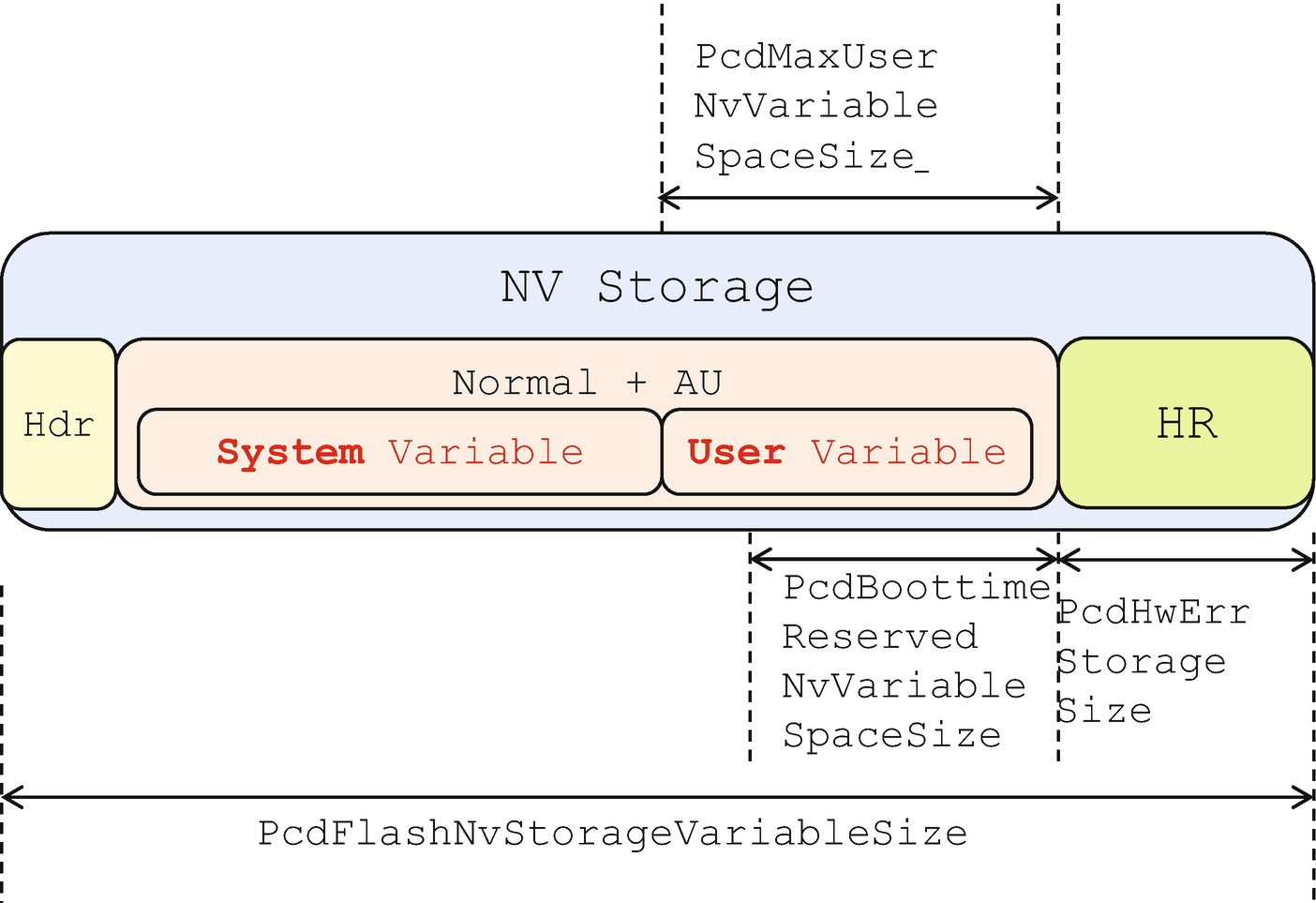
PcdFlashNvStorageVariableSize: The whole variable storage region size on flash
PcdMaxVariableSize: The maximum size of a single non–HwErr-type variable
PcdMaxAuthVariableSize: The maximum size of a single authenticated variable
PcdMaxHardwareErrorVariableSize: The maximum size of a single hardware error record variable
PcdVariableStoreSize: The size of a volatile buffer
PcdHwErrStorageSize: The size of reserved HwErr variable space
PcdBoottimeReservedNvVariableSpaceSize: The size of NV variable space reserved at UEFI boot time
PcdMaxUserNvVariableSpaceSize: The size of maximum user NV variable space
Variable Quota Allocation
PcdHwErrStorageSize indicates the space reserved for the UEFI hardware error logging variable only.
PcdBoottimeReservedNvVariableSpaceSize indicates the space reserved for UEFI boot time. Even if a malicious code writes into the variable space until out of resource state at OS runtime, the BIOS can still write a new variable at boot time.
UEFI-defined variables (gEfiGlobalVariableGuid and gEfiImageSecurityDatabaseGuid variables at least), for example, L“ConIn”, L“ConOut”, L“db”, and L“dbx”
Variables managed by the variable driver internally, for example, L“CustomMode” and L“VendorKeysNv”
Variables that need to be locked and MUST be set by the Variable Lock protocol, for example, L“PhysicalPresenceFlags”
Important variables during platform boot – their properties SHOULD be set by the VarCheck protocol – for example, L“MemoryOverwriteRequestControl”, L“MemoryOverwriteRequestControlLock”, and platform setup variable for system configuration
If a variable is not a system variable, it is a user variable.
System variables can be authenticated variables or non-auth variables. User variables can also be authenticated variables or non-auth variables.
The reason the EDK II variable driver supports a limit for user NV variables is that the variable driver wants to make sure there is enough space for system variables. System variables are critical for system boot. User variables are less important.
When the quota limitation is hit, the EDK II variable driver needs to record the error. Then a platform owner may take action to recover the system to a good state.
This error information is recorded in the L“VarErrorFlag” variable. The EDK II variable driver uses 1 byte to record the error. 0xFF means no error. 0xEF means system variable out of space. 0xFE means user variable out of space. If the system gets a 0xEE later, it means both system variable and user variable are out of space.
System variable out of space: Enter Setup to let the user load default settings; or force clear the variable region and treat as a first boot.
User variable out of space: Prompt a setup page and list all user variables to let the user select which user variables to be deleted or just delete all user variables.
Flash Wear-Out Protection
The SPI is a NOR flash device. In order to change a bit from 1 to 0, the code can send a WRITE command to the device to update 1 byte. However, in order to change a bit from 0 to 1, the code must send an ERASE command to the device to erase a 4 KiB or 64 KiB block to all 1s and then send a write command to update 1 byte. Ideally, the user is free to set configuration at any time. However, the SPI flash device has the ERASE limitation. When the number of flash ERASE actions reaches the limit, the flash is no longer usable.

Variable Storage Format
Each individual variable is saved after the variable storage header. 0x55AA in StartId of a variable header means there is a new variable storage. 0x3F in the State field means it is a valid variable added. 0x3D in the State field means it is deleted. In some rare case, system reset during variable update, a 0x7F in the State field means only the header is valid and no real variable data written. 0x3E in the State field means this variable is in delete transition.
- 1)
The old variable state is marked as InDeleted.
- 2)
The new variable full header is added with state unchanged (0xFF).
- 3)
The new variable state is changed to Header Valid state.
- 4)
New variable full data is added.
- 5)
The new variable state is changed to Added.
- 6)
The old variable state is marked as deleted.

Variable Update Flow
From the preceding variable update flow, when a variable is updated, it is actually not UPDATED in the original place, but marked as DELETED in the original place and then ADDED in a new place. If a user updates the variable several times, the non-volatile storage will have many DELETED variables which are useless but occupy storage space.
- 1)
When updating a variable or adding a new variable and there is not enough free space
- 2)
On exiting the OEM phase (EndOfDxe event) and there is not enough remaining free space
- 3)
On initialization and the variable storage free space is not all 0xFF (there must be something wrong)
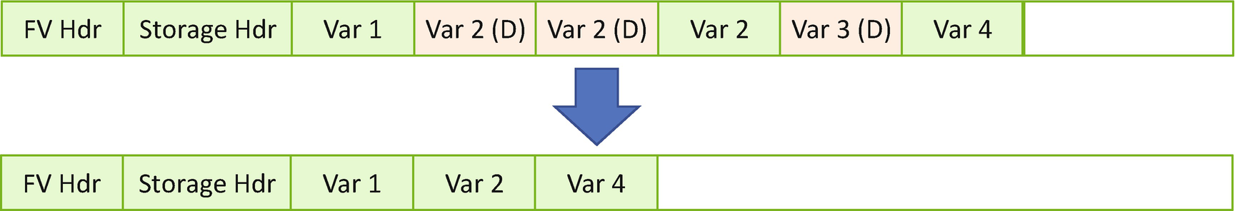
Variable Reclaim
Ideally the variable reclaim should not happen frequently. However, the malicious attacker may manipulate a variable update service in a dramatic way and trigger variable reclaim again and again. Then the flash ERASE command is sent again and again, and finally that action causes the flash device to become broken.
To prevent this from happening, the ERASE command shall be only allowed at boot time within the OEM manufacture code . The ERASE command should be disabled at runtime. Only flash write is allowed to support a limited number of configurations. As such, the attacker has to boot the system again and again to perform the wear-out attack. Because the system reboot needs time, this can reduce the risk of flash wear-out.
Variable Atomicity
As we discussed how to update variable in the preceding section, only 1-byte write from bit 1 to bit 0 can be atomic for the NOR flash device from the hardware perspective. This state is designed to maintain atomicity of individual variables from the software perspective. Each variable exists in ALL-or-NONE state. A partial variable is not allowed. See Figure 11-19.
Fault-Tolerant Write
Individual variable atomicity is maintained by the variable update flow. However, during variable reclaim, the flash block will be erased and written again. In that period of time, if there is a power loss or system shutdown due to a user mistake, the variable firmware volume will be partially destroyed. That means if a variable crosses a flash block, it might be partially correct. The atomicity is broken in this scenario, which is not acceptable.
Fault-tolerant write (FTW) is designed to handle this situation. The EDK II FTW driver is not included in the variable driver. It is a standalone driver to provide the capability of fault-tolerant write. Every flash update driver can consume the FTW protocol API to update the flash part in a safe manner.
- 1)
FTW working block: This is a block to record a write action. It is the record block, not the data block.
- 2)
FTW spare block: This is a real data block to save the data. It must be bigger than the size of the block required to perform the update. In this case, it must be bigger than the variable region.
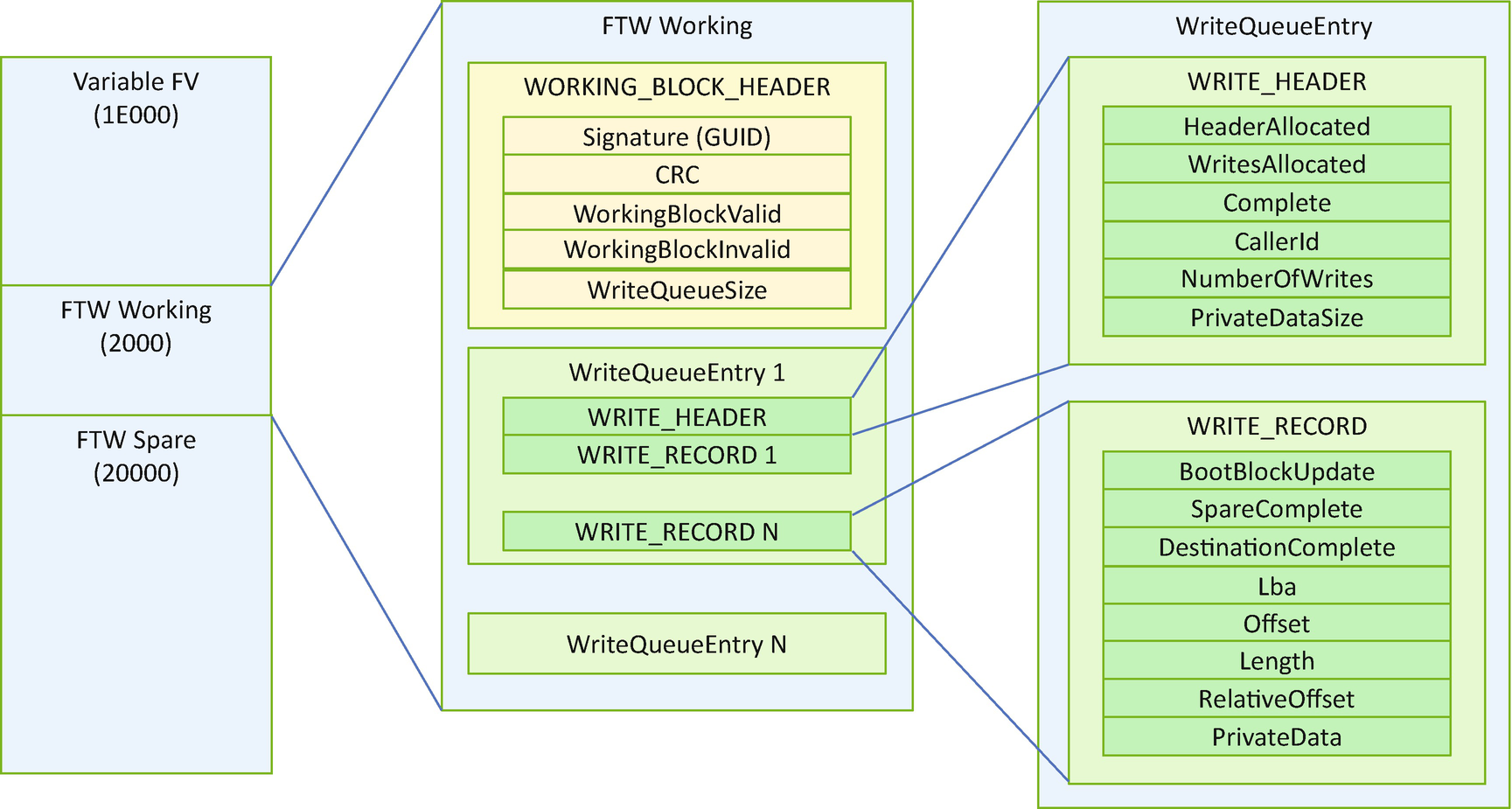
Fault-Tolerant Write Flash Layout
The signature field of the WORKING_BLOCK_HEADER is used to identify if it is the FTW working block. After the header, there will be multiple WriteQueueEntry’s. Each WriteQueueEntry has one WRITE_HEADER and one or more WRITE_RECORDs. The number of WRITE_RECORDs is recorded as the NumberOfWrites fields of the WRITE_HEADER. The most important fields are the Complete field of the WRITE_HEADER, the SpareComplete, and the DestinationComplete of the WRITE_RECORD. Those fields record the status of writes and guarantee the fault tolerance.
- 1)
Step 1: When FTW->Write() is invoked, this API will record the request in the FTW working block.
- 2)
Step 2: This API finds SpareBuf on the FTW spare flash area and backs it up to memory.
- 3)
Step 3: This API writes NewData to the FTW spare block, instead of the variable FV.
- 4)
Step 4: After that, it sets the SpareComplete flag in the FTW working block.
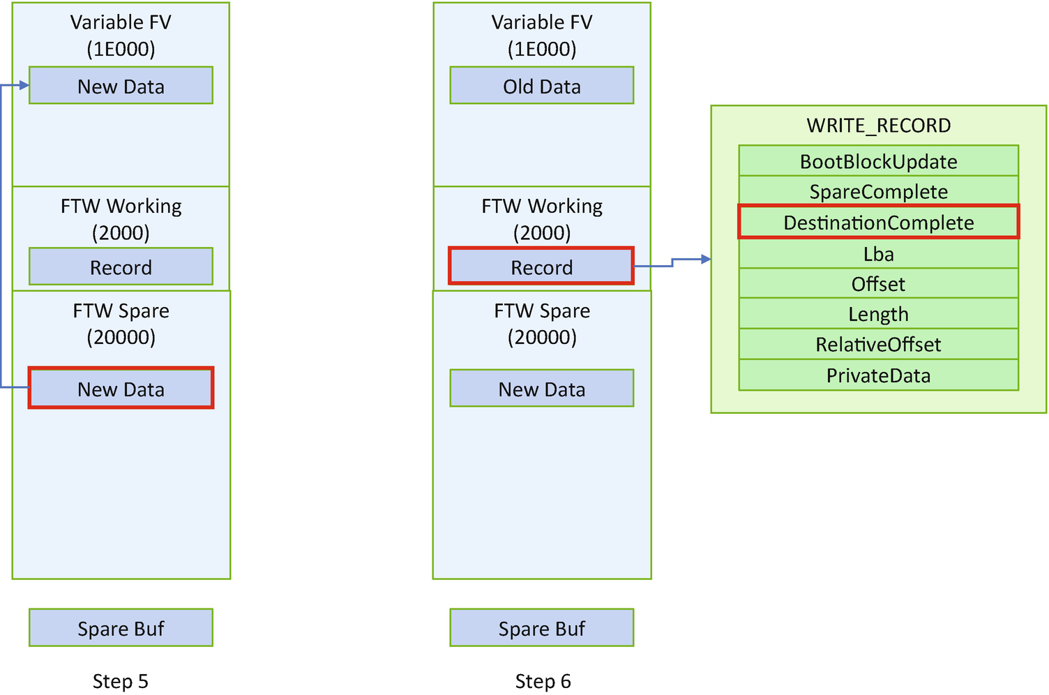
- 5)
Step 5. This API writes NewData from the FTW spare block to the variable FV.
- 6)
Step 6: After that, it sets the DestinationComplete flag in the FTW working block.
- 7)
Step 7: If it is the last WRITE_RECORD associated with WRITE_HEADER, this API sets the Complete flag in WRITE_HEADER.
- 8)
Step 8: SpareBuf is restored in the FTW spare block. Then FTW->Write() finishes.

FTW Steps 1 and 2

FTW Steps 3 and 4
FTW Steps 5 and 6

FTW Steps 7 and 8
Confidentiality Protection
The UEFI specification defines the variable interface for authenticated variables, which provides integrity protection against a software attacker. However, there might be some variable usage that requires the confidentiality protection, such as a WIFI pre-shared key (PSK) in the preboot phase to support further reconnection, a Bluetooth pairing key information for reconnection, and a storage volume key to decrypt the disk. A platform firmware may choose a different authority – a user or a platform hardware entity based upon the use case.
User Key Encrypted Variable
If a user is required to provide the authorization for the variable access, the variable data is bound to a user. If another person takes the machine, they cannot decrypt the variable content. The data migration is easy. If a user copies the data to another machine, they can still access the same data. The only disadvantage is that the physical user must be present to perform the user authentication.
We have discussed the three types of user authentication in Chapter 10: 1) what the user knows, such as password; 2) what the user has, such as hardware token; and 3) what the user is, such as biometrics. Take the user password as an example. In this case, the password itself can be used as a root key to derive the encryption key. Then the encryption key can be used to encrypt or decrypt the variable data.
Platform Key Encrypted Variable
If a platform is required to provide the authorization for the variable access, the variable data is bound to a platform. It is different from the user binding. If another person takes the machine, they may get the decrypted content because the platform authority has zero knowledge on which user is using the machine. If data migration is needed, the user must use the old platform authority to decrypt the data, copy data to a new machine, and use the new platform authority to encrypt the data.
In practice, there could be different platform authorities. For example, the Trusted Platform Module (TPM) Platform Configuration Register (PCR) could be used to seal the variable data or the key to encrypt the variable data. The sealed object is saved in the TPM non-volatile storage. When the firmware wants to get the variable, it just sends an unseal command to the TPM device. It is the TPM hardware that checks and returns the data if the PCR policy matches. We have discussed this in Chapter 7 and previous sections – variable with TPM storage.
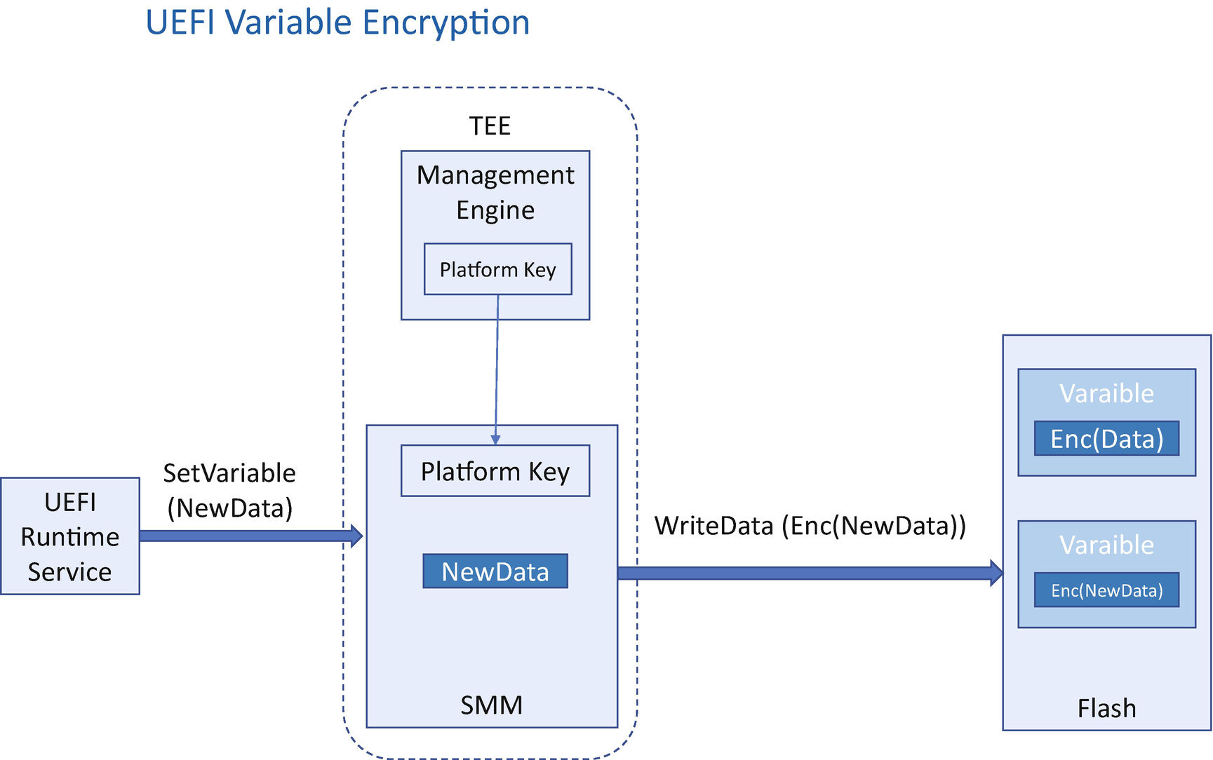
Variable Encryption
The platform key–based encryption might not able to resist the software attacker because an attacker may just write a software program to call the GetVariable service to ascertain the decrypted data. If this is a threat, the solution needs to use another mechanism to prevent the GetVariable service from being invoked.
The user authority and the platform authority can be combined together to provide more security. For example, a solution can use the TPM NV index to save the variable data with the policy PCR (platform authority) and policy password (user authority). If the PCR matches and the user provides the correct password, only then the variable can be decrypted.
Authority of the Confidential Variable
Property | User | Platform |
|---|---|---|
Authentication mechanism | User authentication, such as what a user knows, what a user has, and what a user is. | Platform property, such as TPM Platform Configuration Register (PCR) and platform key – from a secure coprocessor. |
Binding | Bind to a user. If another person takes the machine, they cannot decrypt the variable content. | Bind to a platform. If another person takes the machine, they may get the decrypted content. |
User interaction | Required. | Not required. |
Data Migration | Easy. | Hard. |
Adversary | Software attack, hardware attack | Hardware attack |
Example | User inputs password as encryption key. | Management Engine provides the RPMB key. CSME provides the variable encryption key. TPM PCR seals the variable encryption key. |
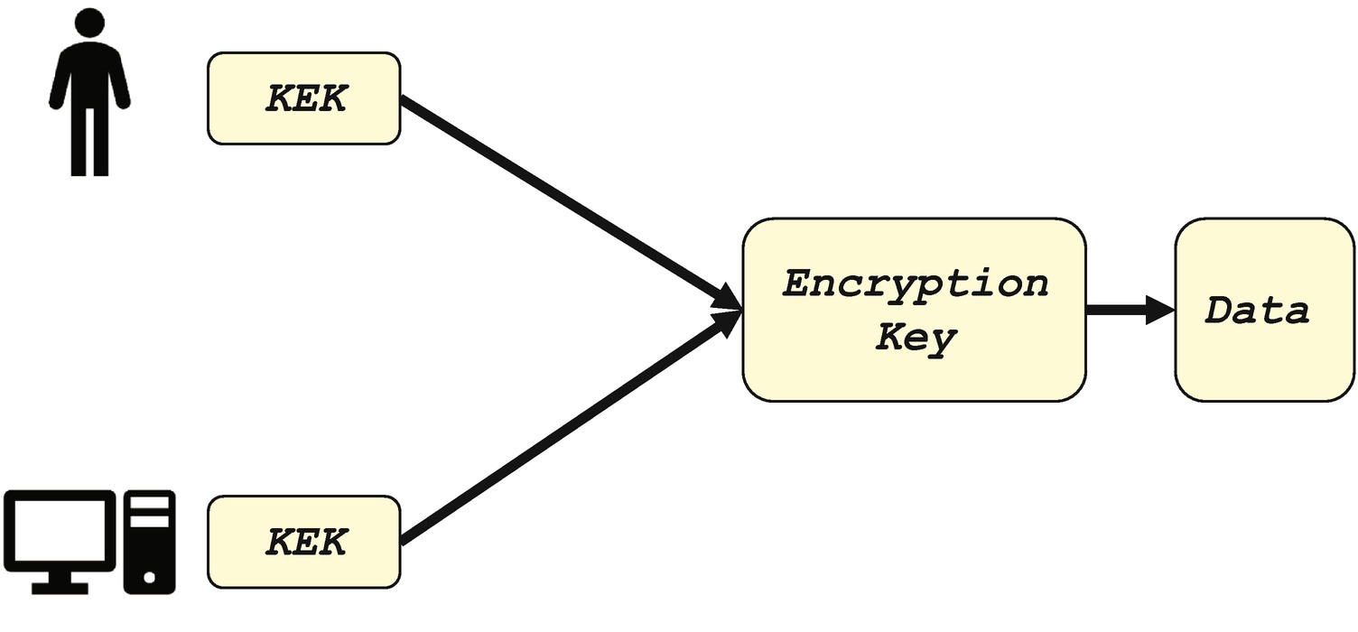
Key Encryption Key
The key from the user or the platform can also be used as the root key to create a key hierarchy (see Figure 11-25). The root key can be used to encrypt the subkey. It is the subkey that encrypts the final secret variable data. The subkey can be created by the user and saved into the NV storage area. The subkey can also be derived from the root key automatically by using a key deviation function such as the HMAC-based key deviation function (HKDF), for example:
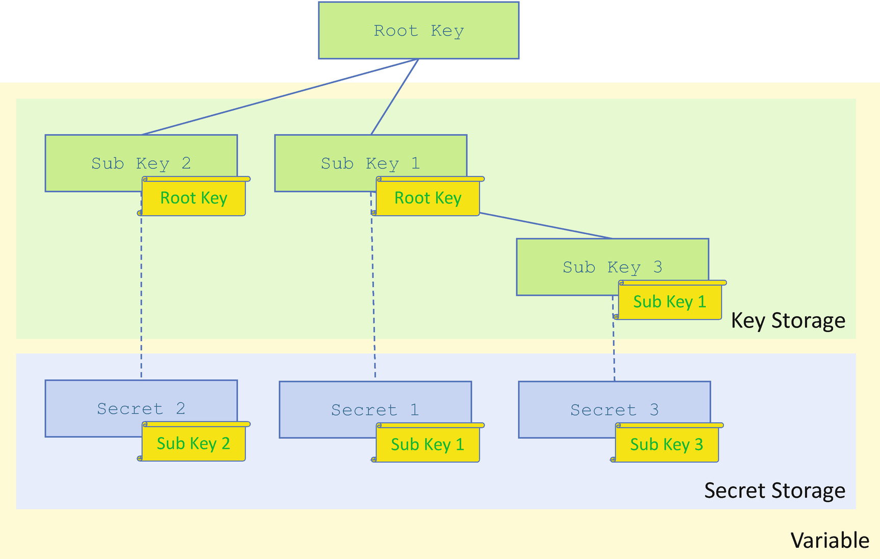
Key Hierarchy
The encrypted variable data is only on the flash region. For performance considerations, the variable data may save a copy of the decrypted variable data in the memory as a cache to support GetVariable() API. In this case, we need other technologies to resist the hardware attack to the system memory, such as Total Memory Encryption (TME).
Attack and Mitigation
Now, let’s take a look at some real use cases for the attack against UEFI variables and mitigation.
Malformed Input
The authenticated variable requires the signature verification. The attacker may construct a malformed variable input data, such as no signing data or bad signing data. The signing verification code should reject the no signing data as well as the bad signing data.
Bypass the Protection: TOC/TOU Attack
Similar to the image signing verification, the variable authentication and update must happen in a trusted execution environment, such as SMM. Both authentication and update must be in one SMI handler.
Bypass the Protection: Authentication Disabled
When UEFI secure boot was introduced, some firmware used another read/write variable to control the secure boot on/off. As such, the attacker just needed to control this read/write variable to disable the secure boot feature to turn off all the signing verification. This is not a secure implementation. The secure boot disable capability must be a platform policy and require physical user presence. Also, this disable action must be recorded to a measurement log to provide the attestation that the platform configuration is NOT secure.
Bypass the Protection: Variable Lock Disabled
Ideally, the read-only variable should be locked in any possible boot path, such as normal boot, S3 resume, capsule update, and so on. If this read-only variable is not locked in a special boot path, then the attack may trigger this patch and modify the variable content.
Replay Attack: Software

Replay Attack – Software
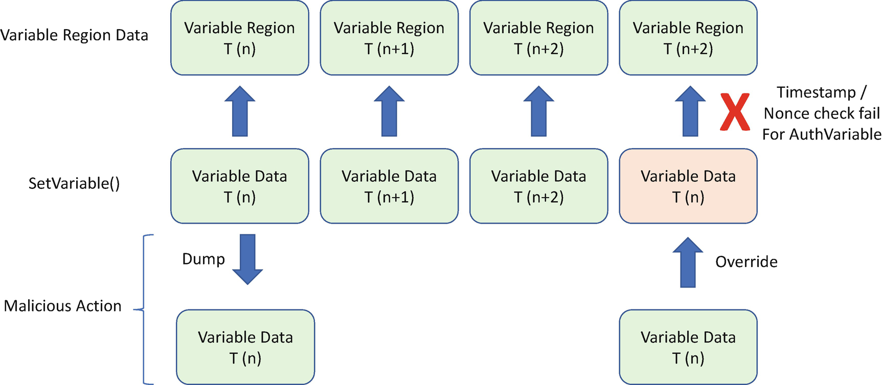
Replay Attack Prevention – Time-Based/Nonce-Based Auth Variable
Replay Attack: Hardware
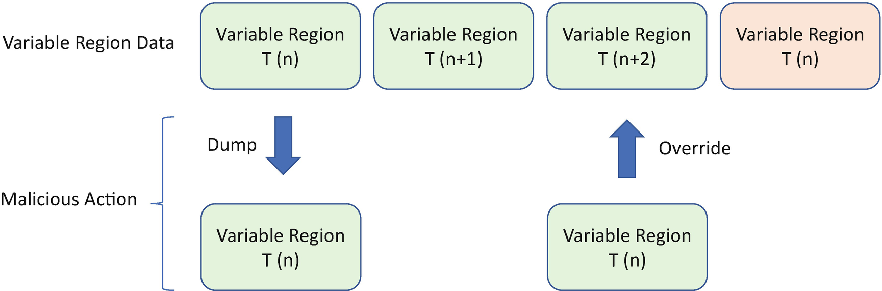
Replay Attack – Hardware

Replay Attack Prevention with RPMB

Replay Attack Prevention with RPMC
Rollback Attack

Rollback Attack – RPMC-Based Variable
Flash Wear-Out Attack
We have discussed the flash wear-out protection in the previous section. The key is to lock the flash erase action after OEM platform manufacture code. Care must be taken that this lock must happen in any boot mode, such as normal boot, S4 resume, S3 resume, flash update, recovery, manufacturing mode, and so on.
Partial Update Attack
An attacker may power off the system during the variable data update. One possibility is that an individual variable is partially updated with the flash WRITE command. The other possibility is that the variable block region is partially updated with the flash ERASE command. The BIOS must have ways to detect both scenarios based upon the hardware limitation. If the hardware can guarantee the data updating at the block level, the detection mechanism shall be in the block-based mechanism, such as a Replay Protected Memory Block (RPMB) device. If the hardware can guarantee the data updating at the byte level, the detection mechanism shall be at the byte level, such as a Replay Protected Monotonic Counter (RPMC)–capable SPI device.
For the individual variable update, the variable atomicity must be guaranteed, which we have discussed in the previous section. Each variable exists in ALL-or-NONE state.
For the variable block region update, the fault-tolerant write must be used, which we have also discussed in the previous section. The variable region can be recovered on the next boot if the corruption is detected.
UEFI PI Firmware Volume
UEFI PI Configuration FV Protection Mechanism
Mechanism | Resist Software Attack | Resist Hardware Attack |
|---|---|---|
Integrity Protection | Flash region lock Signed Update, such as UEFI signed capsule update. | Hardware root-of-trust based verification, such as Intel Boot Guard, Intel Platform Firmware Resilience |
Availability Protection | Flash Wear-out Protection Update Version Check | Fault Tolerant Write Default/Golden Configuration Recovery |
Confidentiality Protection | User-Key Encryption | Platform-Key Encryption User-Key Encryption |
UEFI PI PCD (Platform Configuration Data)
UEFI variables provide read/write configuration data support based upon a name/GUID pair. Besides UEFI variables, the UEFI Platform Initialization (PI) specification defines the Platform Configuration Database (PCD) concept to abstract the configuration data with a token ID. The PCD could be static data fixed at build time or dynamic data editable at runtime.
PcdsFeatureFlag: This type of PCD only supports 1/0. The caller uses FeaturePcdGet() to retrieve the value. This type of PCD is mapped to be a MACRO so that a compiler optimization can remove the code scoped by “if(FALSE)”. It is not allowed to set as a PcdsFeatureFlag.
PcdsFixedAtBuild: This type of PCD can be mapped to a global variable if the caller uses PcdGet() or a MACRO if the caller uses FixedPcdGet(). As such, this type of PCD can be used in a data structure definition. It is not allowed to set as a PcdsFixedAtBuild.
PcdsPatchableInModule: This type of PCD is mapped to a global variable. It is allowed for use by both PcdGet and PcdSet. If PcdSet is called, it only changes the module-level PCD value instead of the system-level PCD value. Only the current module sees the PCD change. Other modules still see the original value.
PcdsDynamicDefault: PcdsDynamicDefault is mapped to a PPI or protocol. It is allowed for both PcdGet and PcdSet. PcdSet changes the system-level PCD value immediately. This type of PCD value is volatile. The changed value will not be saved on the next boot.
PcdsDynamicHii: PcdsDynamicHii is mapped to a UEFI variable. It is non-volatile. As such, the changed value can be saved on the next boot. However, the tricky thing is that this PCD value depends on the readiness of the UEFI variable services. If PcdGet is called before UEFI variable services are ready, the default PCD value will be returned instead of the updated PCD value. We suggest that the platform owner be very careful of this trap. If DXE PcdGet is required before the UEFI variable services are ready, we suggest that the platform define the PCD with the access type of PcdsDynamicDefault and then use the value returned by GetVariable in the PEI phase. A nonsecure bootrelated variable can be set in this PCD’s value.
PcdsDynamicVpd: PcdsDynamicVpd is used to map configuration data to a static flash region so that a tool can modify the values after the flash image is generated. This is used by a BIOS that needs to support binary configuration after build. Intel Firmware Support Package (FSP) is an example that uses PcdsDynamicVpd. The dynamic VPD can also be map to a configuration FV and updated via UEFI signed capsule.
PcdsDynamicEx: PcdsDynamicEx supports external modules for binary build. If a UEFI module (DXE driver or PEIM) is not built with the system firmware, the dynamic PCD must be declared as PcdsDynamicEx. If a platform wants to include this binary EFI module, the binary module INF must be included in the DSC file. As such, the PCD database will include the external PCDs declared in this binary module. This is important since the PCD database only includes PCDs that are used by a module.
SkuIds: SkuIds allow the building of one UEFI firmware image that boots on multiple boards with a different configuration in each board. It can support multiple board configurations generated at build time and then support runtime selection to make one configuration active.
DefaultStores: DefaultStores is a special usage of PCD (gEfiMdeModulePkgTokenSpaceGuid.PcdSetNvStoreDefaultId). The use case of DefaultStores is to create different default stores in different boot modes, such as standard boot mode, manufacturing boot mode, or safe boot mode. The configuration data is set to (gEfiMdeModulePkgTokenSpaceGuid.PcdNvStoreDefaultValueBuffer). All those default stores are configured at build time and selected at runtime according to the boot mode. The default store PCD can be consumed by the HII database to support a BIOS setup “load default” operation.
Static (FeatureFlag or FixedAtBuild) PCD is built in the code. The PcdsDynamicDefault is implemented as a standard PPI or protocol in memory. They have no attack surface. From a security perspective, the only potential attack surface is PcdsDynamicVpd and PcdsDynamicHii.
VPD is used to provide the static configuration data in a flash region. Because the data is not runtime updatable, it is similar to the firmware code. As such, signing-based verification can be used for the VPD region.
Dynamic HII PCDs can be mapped to the UEFI variables. All the protection mechanisms for UEFI variables can also be used for dynamic HII PCDs.
Summary
In this chapter, we discussed firmware configuration. We use UEFI variables as an example. In the next chapter, we will discuss the non-host firmware.
References
Conference, Journal, and Paper
[P-1] Jiewen Yao, Vincent Zimmer, Star Zeng, “A Tour Beyond BIOS Implementing UEFI Authenticated Variables in SMM with EDK II,” Intel Whitepaper, https://github.com/tianocore-docs/Docs/raw/master/White_Papers/A_Tour_Beyond_BIOS_Implementing_UEFI_Authenticated_Variables_in_SMM_with_EDKII_V2.pdf
[P-2] Yuriy Bulygin, Andrew Furtak, Oleksandr Bazhaniuk, John Loucaides, Corey Kallenberg, Xeno Kovah, John Butterworth, Sam Cornwell, “All your boot are belong to us,” in CanSecWest 2014, available at https://cansecwest.com/slides/2014/AllYourBoot_csw14-mitre-final.pdf, and www.c7zero.info/stuff/AllYourBoot_csw14-intel-final.pdf
[P-3] Yuriy Bulygin, Andrew Furtak, Oleksandr Bazhaniuk, “A Tale of One Software Bypass of Windows 8 Secure Boot,” in BlackHat US 2013, available at www.c7zero.info/stuff/Windows8SecureBoot_Bulygin-Furtak-Bazhniuk_BHUSA2013.pdf
[P-4] Yuriy Bulygin, John Loucaides, Andrew Furtak, Oleksandr Bazhaniuk, Alexander Matrosov, “Summary of Attacks Against BIOS and Secure Boot,” in DEF CON 22, available at www.c7zero.info/stuff/DEFCON22-BIOSAttacks.pdf
[P-5] Yoongu Kim, Ross Daly, Jeremie Kim, Chris Fallin, Ji Hye Lee, Donghyuk Lee, Chris Wilkerson, Konrad Lai, Onur Mutlu, “Flipping Bits in Memory Without Accessing Them: An Experimental Study of DRAM Disturbance Errors,” in IEEE 2014, available at http://users.ece.cmu.edu/~yoonguk/papers/kim-isca14.pdf
[P-6] Mark Seaborn, Thomas Dullien, “Exploiting the DRAM rowhammer bug to gain kernel privileges,” in project zero 2015, available at https://googleprojectzero.blogspot.com/2015/03/exploiting-dram-rowhammer-bug-to-gain.html
[P-7] Anil Kurmus, Nikolas Ioannou, Matthias Neugschwandtner, Nikolaos Papandreou, Thomas Parnell, “From random block corruption to privilege escalation: A filesystem attack vector for rowhammer-like attacks,” in USENIX 2017, available at www.usenix.org/system/files/conference/woot17/woot17-paper-kurmus.pdf
Specification and Guideline
[S-1] NVM Express Org, “NVM Express Specification,” 2019, available at https://nvmexpress.org/resources/specifications/
[S-2] JEDEC Org, “Universal Flash Storage,” 2018, available at www.jedec.org/standards-documents/focus/flash/universal-flash-storage-ufs
[S-3] JEDEC Org, “e-MMC,” 2019, available at www.jedec.org/standards-documents/technology-focus-areas/flash-memory-ssds-ufs-emmc/e-mmc
[S-4] Intel, “Serial Flash Hardening Product External Architecture Specification,” 2013, available at www.intel.com/content/www/us/en/support/articles/000020984/software/chipset-software.html
[S-5] Trusted Computing Group, “Trusted Platform Module Library,” 2016, available at https://trustedcomputinggroup.org/resource/tpm-library-specification/
[S-6] UEFI Organization, “UEFI Specification,” 2019, available at www.uefi.org/
[S-7] UEFI Organization, “UEFI Platform Initialization Specification,” 2019, available at www.uefi.org/
[S-8] Intel, “Intel TXT Software Development Guide,” 2017, available at
www.intel.com/content/www/us/en/software-developers/intel-txt-software-development-guide.html
[S-9] IETF, “RFC 5869 – HMAC-based Extract-and-Expand Key Derivation Function (HKDF),” 2010, available at https://tools.ietf.org/html/rfc5869
Web
[W-1] Chromium TPM usage, www.chromium.org/developers/design-documents/tpm-usage
[W-2] BitLocker Drive Encryption Overview, https://docs.microsoft.com/en-us/windows/security/information-protection/bitlocker/bitlocker-device-encryption-overview-windows-10
[W-3] eCryptfs: An Enterprise-class Encrypted Filesystem for Linux, www.kernel.org/doc/ols/2005/ols2005v1-pages-209-226.pdf
[W-4] Windows Quota, https://docs.microsoft.com/en-us/windows-server/storage/fsrm/quota-management
[W-5] Linux Disk Quota, https://access.redhat.com/documentation/en-us/red_hat_enterprise_linux/6/html/storage_administration_guide/ch-disk-quotas