Chapter 18
Cable Properties and Propagation of Action Potentials
Chapter Outline
III. Frequency-Modulated Signals
V. Conduction of Action Potentials
VI. External Recording of Action Potentials
Appendix 1 Additional Discussion of Input Resistance and Impedance
Appendix 2 Propagation in Cardiac Muscle and Smooth Muscles
AIV. Electronic Model for Simulation of Propagation
I Summary
Although the biological cable (i.e. nerve fiber or skeletal muscle fiber) is the best possible, it is a relatively poor cable with a short length constant and relatively long time constant. Therefore, for faithful and rapid signal transmission over long distances, energy must be put into the system at each point along the way. The system evolved is that of action potential (AP) generation, which are all-or-none signals of constant amplitude and constant propagation velocity, in addition to having refractory periods and sharp thresholds. This is a frequency-modulated system, in which increasing strength of sensation or motor response follows from an increase in frequency of the AP signals.
AP propagation occurs by means of local-circuit currents. The transmembrane current has three phases: outward, inward and outward. The internal and external longitudinal currents have two phases: forward and backward (for internal) or backward and forward (for external). The external currents use the path of least resistance, enabling electrograms (e.g. ECG, EMG) to be recorded from the body surface. The compound AP is graded in amplitude, reflecting the summation of the external currents generated from each fiber that is activated; i.e. the more fibers simultaneously activated, the greater the amplitude of the electrogram signal.
Propagation velocity is faster when (1) the diameter of the fiber is larger, (2) the length constant is longer, and (3) the time constant and capacitance are lower. The myelin sheath evolved by vertebrates enables much faster propagation velocity and at a lower energy cost. Myelination raises the effective membrane resistance and lowers the effective capacitance. Excitability occurs only at the short nodes of Ranvier that periodically interrupt the myelin sheath. Therefore, the AP signal jumps from node to node in a saltatory pattern of conduction.
II Introduction
The resting potential (RP) of cells enables the electrogenesis of action potentials and excitability. In this chapter, we examine the mechanism for propagation of the APs and excitability from one part of a neuron or muscle to a distal part.
It is imperative that the body be able to transmit a signal from one point to another very rapidly. The only way that this can be accomplished is by an electrical mechanism. Blood flow and diffusion and signaling molecules are much too slow to allow rapid signaling. In contrast, electricity flows very quickly, at the speed of light (3 × 10⁸ m/s) in a copper wire or about one-ninth the speed of light in a water solution (like the composition of the body). (The velocity of electricity in solution is equal to the velocity of light (c) divided by the square root of the dielectric constant of water [which is 81].) Therefore, the body makes use of electricity for rapid signaling in the nervous system, skeletal muscle, heart and smooth muscles. Propagation velocity is about 120 m/s in our fastest nerve fibers, about 6 m/s in skeletal muscle, about 0.5 m/s in heart and about 0.05 m/s in smooth muscle (Table 18.1).
TABLE 18.1. Conduction Velocity as a Function of Fiber Diameter in Nerve Axons and Muscle Fibers
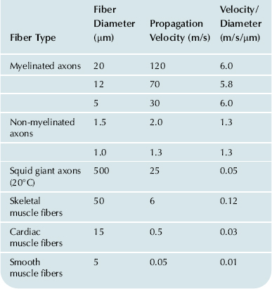
One example of the need for very fast communication or signaling is the process of walking. Very rapid signals must travel from the motor cortex of the brain, down to the lower spinal cord region and out the motor axons to the skeletal muscles of the lower extremities (Fig. 18.1). In this process, the signal crosses one or more synapses, which are regions in which one neuron ends and the next one begins and in which a special chemical neurotransmitter signal is involved (Fig. 18.2). At the termination of each branch of a motor nerve axon on the skeletal muscle fiber, there is another synapse, known as the neuromuscular junction or motor end-plate (see Fig. 18.1). The signal crosses the neuromuscular junction and gives rise to an AP in the muscle fiber that propagates in both directions from the motor end-plate. The muscle AP elicits contraction. Receptors in the muscles (e.g. stretch receptors) transmit information (in the form of propagating APs) back into the central nervous system (CNS). Thus, in walking, there is a continuous rapid flow of information and instructions to the muscles in both directions: out of the CNS and into the CNS. Therefore, even a relatively simple skeletal activity such as walking would not be possible without a very rapid signaling system. To illustrate, in various demyelinating diseases (e.g. caused by some viruses, heavy metals, autoimmune reactions), loss of the myelin sheath around the myelinated nerve fibers causes propagation to become slowed and impaired in the affected nerve fibers, with associated incoordination and partial paralysis.
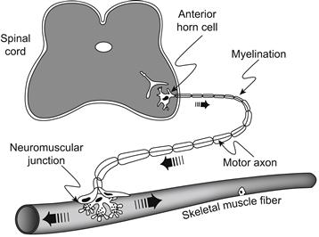
FIGURE 18.1 Schematic diagram of a motor axon, with the cell body (soma) in the anterior horn of the spinal cord and its terminal branches ending on skeletal muscle fibers (only one muscle fiber depicted) to form the neuromuscular junctions (motor end-plates). Each motor axon with its attached skeletal muscle fibers is known as the motor unit. The motor axons are of large diameter (e.g. 20 μm) and are myelinated and therefore propagate at fast velocities (e.g. 120 m/s). As a consequence of the chemical synaptic transmission process at the neuromuscular junction, an AP is initiated in the muscle fiber and propagates in both directions, bringing about contraction.
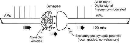
FIGURE 18.2 Diagram of a chemical excitatory synapse between two nerve fibers. An AP in the presynaptic fiber (left) brings about the release of the neurotransmitter at its nerve terminal. The transmitter molecules rapidly diffuse the short distance (e.g. 0.1 μm) across the synaptic cleft, bind to receptor sites on the postsynaptic membrane and open the associated non-selective ion channels (Na+, K+ mixed conductance) complexed to the receptor (i.e. these are ligand-gated ion channels). The associated synaptic current depolarizes the postsynaptic membrane, producing the excitatory postsynaptic potential (EPSP); this depolarization spreads passively into the adjacent conductile membrane (excitable) because of cable properties, thereby triggering one or more APs in the postsynaptic axon. The EPSPs are local, graded in amplitude and non-refractory whereas the APs are all-or-none (maximal), refractory and propagated actively. Thus, the AM synaptic process gives rise to an FM or digital signal. The strength of a biological response (e.g. contraction, secretion, sensation) is a function of the frequency of the signal. That is, higher AP frequency corresponds to stronger contraction or stronger sensation.
III Frequency-Modulated Signals
Because propagating all-or-none APs are all very similar to each other (in shape, duration, amplitude, rate of rise and propagation velocity), to make the signal stronger or weaker, the body increases or decreases, respectively, the frequency of the APs. That is, the body uses a frequency-modulated (FM) system, rather than an amplitude-modulated (AM) system (see Fig. 18.2). It is a digital system composed of on-off identical signals. At each synapse, the signal becomes graded in amplitude rather than all-or-none: the greater the amplitude and duration of the local postsynaptic potential, the higher the frequency of APs triggered. The same is true of the local graded receptor potential generated at some sensory organs/receptors. Stronger signals translate into a higher frequency of impulses, and weaker signals correspond to a lower frequency of impulses.
IV Cable Properties
IVA Biological Fiber as a Cable
An electrical cable consists of two parallel conductors separated by insulation material, e.g. two copper wires separated by rubber. Usually one of the conductors is arranged as a tubular sleeve surrounding a central solid rod (wire), as depicted in Fig. 18.3A. The equivalent electrical circuit for a cable is shown in Fig. 18.3B: two parallel conductors (wires) separated by a transverse resistance (R) shown distributed along the length of the cable. The resistance of the conductors is so small, compared with the transverse insulation resistance, that it is assumed to be zero. In the case of the biological cable (a long narrow nerve fiber or skeletal muscle fiber), one parallel conductor is the inside fluid (cytoplasm) and the second parallel conductor is the outside fluid surrounding (bathing) the cell (the interstitial fluid). Because the conductivity of biological fluid is much less (i.e. much higher resistance) than that of copper wire and because the cross-sectional area of the cell is so small, the inside longitudinal resistance is high and cannot be ignored (Fig. 18.3C). The outside longitudinal resistance is relatively small, as compared with the inside, because of the larger volume (cross-sectional area) of fluid available to carry the outside current, and therefore is assumed to be negligible (Taylor, 1963).
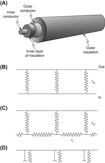
FIGURE 18.3 A coaxial cable and associated electrical equivalent circuit (A, B) and the electrical equivalent circuit for a biological cable (C, D). (A) The coaxial cable consists of an inner conductor (e.g. copper wire) and an outer concentric conductor separated by a layer of insulation (e.g. rubber). (B) The equivalent circuit for a coaxial cable. The inner and outer conductors are depicted as having nearly zero resistances and the transmembrane insulation resistance is shown distributed along the length of the cable. (C) In the biological cable, the inner conductor is the cytoplasm (axoplasm or myoplasm), which is not of negligible resistivity and therefore is depicted as ri distributed along the length of the fiber. The transverse insulation resistance is the cell membrane resistance (rm). (D) Addition of the capacitance elements to the biological cable (cm), which arise due to the lipid bilayer matrix of the cell membrane.
In addition, there is a stray capacitance distributed along the length of the cable (see Fig. 18.3D), because a capacitance occurs when two parallel conductors (“plates”) are separated by a high-resistance dielectric material. The dielectric constant of materials is related to vacuum, which is assigned a value of 1.0000; air has a value very close to vacuum, oils have a value of 3–6 and that of pure water is 81. The biological membrane, which has a matrix of phospholipid molecules, has a dielectric constant of about 5, typical of oils. The higher the dielectric constant, the higher the capacitance. The closer the parallel plates, the higher the capacitance. Because the biological membrane is so thin (approx.70 Å or 7 nm), its capacitance is relatively high. All cell membranes have a membrane capacitance (Cm) of about 0.7–1.0 μF/cm2 (where F stands for farads (Cole KC, 1965)).
IVB Length Constant
In the electric cable depicted in Fig. 18.3A and B, a voltage (or signal) applied at one end would be transmitted to the distant end with little or no decrement (diminution or attenuation) and the so-called length constant would be very long or nearly infinite. In the biological cable (see Fig. 18.3C and D), however, a signal applied at one end rapidly falls off (decays) in amplitude as a function of distance, with a relatively short length constant (λ). This decay in voltage is exponential (Fig. 18.4A). An exponential process gives a straight line on a semilogarithmic plot (log V versus distance) (Fig. 18.4B). In a cable, the relationship between the voltage at any distance (x) from the applied voltage (V0) is:
 (18.1)
Thus, when x = λ
 (18.2a)
The mathematical solution to Equation 18.1 is:
 (18.2b)
 (18.2c)
Hence, the distance at which the voltage decays to 36.8% of the initial value gives the length constant, λ. In nerve fibers and skeletal muscle fibers, λ has a value of only about 1–3 mm.
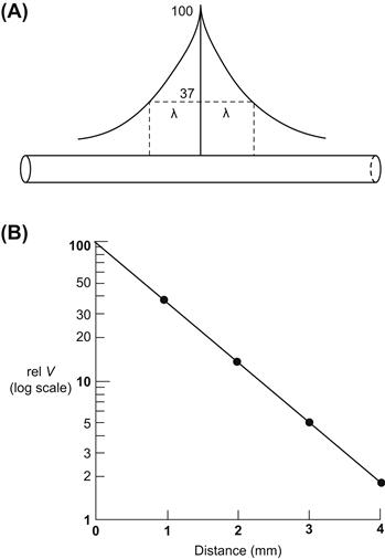
FIGURE 18.4 Length constant of the biological cable (fiber). (A) The exponential decay of voltage on both sides of an applied current (voltage) as a function of distance is diagrammed. The distance at which the voltage falls to 1/e or 36.8% of initial voltage (at x = 0), gives the λ value. (B) When the voltage is plotted on a log scale against distance, a straight line is obtained.
Therefore, the relatively short λ, compared with the length of the neuron (e.g. over 1.0 m for a lumbar anterior horn cell motor neuron) or skeletal muscle fiber, means that a signal applied at one end (or midpoint) would fall off very quickly with distance along the fiber (Fig. 18.5). If the length constant were 1.0 mm, then at 4 mm, the signal would become negligibly small. Hence, the electrical signal cannot be conducted passively in the biological cable, because it would decrement and disappear over relatively short distances. The AP (signal) is amplified to a constant value at each point (or each node) in the membrane, as discussed in the following chapter. That is, conduction is active, not passive, with energy being put into the signal at each point to prevent any decay of the signal.
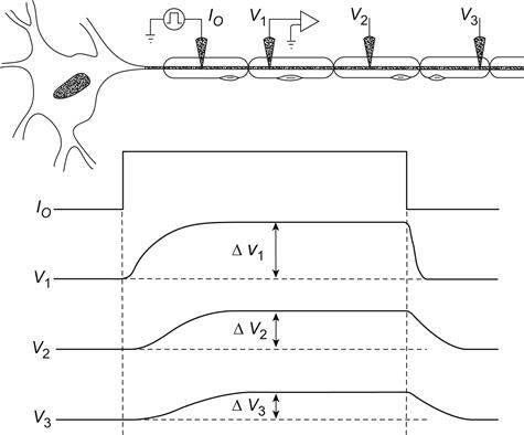
FIGURE 18.5 Diagram of a motor axon and how the voltage signal would decay with distance if the neuron were only a passive cable (non-excitable). The voltage traces illustrate the voltage signals that would be simultaneously recorded at three different points along the axon (V1, V2 , and V3) from the site of injection of a rectangular current pulse (Io). As depicted, the amplitude of the steady-state voltage pulse rapidly falls off with distance, because the length constant (λ) of the biological cable is short (e.g. 1 mm) compared with the length of the axon (e.g. 1000 mm). Therefore, an active response of the cell membrane at each point is required faithfully to propagate the signal. The voltage recorded at point V1 (Δ V1) also illustrates that the membrane potential changes in an exponential manner, both at the beginning of an applied rectangular current pulse and at the end. This exponential change results from the capacitance of the cell membrane, the time constant (τ) being a product of the resistance and capacitance (RmCm). The time it takes for the voltage to decay to 1/e (36.8%) of the initial (maximal) value at the end of the pulse, or to build up to 63.2% (1−1/e) of the maximal value at the beginning of the pulse, gives the τ value.
The parameters that determine the length constant of a cable are the square root of the ratio of the transverse resistance (rm) to the sum of the inside (ri) and outside (ro) longitudinal resistances:
 (18.3)

where rm, ri and ro are the resistances normalized for a unit length (1.0 cm) of fiber.
For surface fibers of a nerve or a muscle bundle bathed in a large volume conductor, ro is negligibly small and Equation 18.3 reduces to:
 (18.4a)
Equation 18.4a is the same as:
 (18.4b)

where a is the fiber radius and Rm and Ri are the membrane resistance and longitudinal cytoplasmic resistance, respectively, normalized for both length (1.0 cm) and cell diameter. Thus, the greater the membrane resistance and the smaller the internal longitudinal resistance (larger cell diameter), the greater the λ value. We will see later that the propagation velocity is a function of λ; i.e. larger diameter fibers propagate faster. We will also see that myelination increases the effective membrane resistance (Rm) and lowers the effective capacitance, thereby increasing propagation velocity.
IVC Time Constant
Because of the high capacitance of the cell membrane (Cm), the membrane potential (Em) cannot change instantaneously upon application of a step current pulse. Instead, Em changes in an exponential (negative) manner (see Fig. 18.5) on both the charge and the discharge. The membrane time constant (τm) is a product of the resistance (Rm) and capacitance of the membrane and can be expressed as:
 (18.5a)
 (18.5b)
where Rm is the resistance in ohms (Ω-cm2), and Cm is the capacitance in farads (F/cm2).
The discharge of the membrane (parallel RC network) is given by:
 (18.6)
where Vt is the voltage at any time t (at the site of current injection) and Vmax is the final maximum voltage attained during the pulse. When t = τ,
 (18.7a)

Hence, the time at which the voltage decays to 36.8% of the initial (maximal) value gives the time constant, τ (see Fig. 18.5). In nerve fibers and skeletal muscle fibers, τm has a value of about 1.0 ms.
When the membrane is charging, there is a similar exponential (negative) process, with the identical time constant (see Fig. 18.5). The corresponding relationship is given by:
 (18.7b)
The time it takes for the voltage to build up to 63.2% of its final value gives the time constant. When t = τ,
 (18.7c)

Thus, the time constant can be measured on the build-up of the pulse (time to reach 63.2% of the final voltage) or on the decay (time to decay to 36.8% of the initial voltage).
IVD Input Resistance
The input resistance (Rin) of a muscle or nerve fiber is essentially the resistance that an intracellular microelectrode “looks” into when a small current (DC pulse) is injected. Thus, Rin is determined by the change in membrane potential (Vo or Vx= 0) at steady-state produced at the site of injection (x = 0) by the injection of a known (measured) amount of current (Io or Ix= 0), based on Ohm’s law.
 (18.8)
If the microelectrode is near the middle of a very long fiber (or “infinite” cable), then Rin is related to the other cable parameters (e.g. to the internal longitudinal resistance ri and the DC length constant λDC):
 (18.9)
The factor of 0.5 is present because current flows in both directions from the microelectrode. If the microelectrode is at one end of the long fiber, then the factor of 0.5 is removed. Equation 18.9 indicates that the Rin is greater when ri and/or λDC are greater. Combining Equations 18.8 and 18.9 gives:
 (18.10a)
or
 (18.10b)
This equation indicates that the change in membrane potential at x = 0 is equal to the applied current (I0) times the input resistance.
To obtain the change in membrane potential at any point x along the fiber cable (Vx), then an exponential term (e−x /λ) must be added to account for the exponential decay of voltage over distance:
 (18.11)
This equation is identical to Equation 18.1, because the Io 0.5 ri λDC term is equal to Vo (Equation 18.10b):

Further discussion is given in Appendix 18.1.
IVE Local Potentials
In contrast to the active propagation of APs, synaptic potentials and sensory receptor potentials are not actively propagated. Such potentials decay exponentially (from their source of initiation) along the fiber cable, as described previously. Therefore, postsynaptic potentials and receptor potentials are local potentials. When local potentials are in the depolarizing direction, they can give rise to APs, which are propagated; when hyperpolarizing, they act to inhibit production of APs. These local potentials are similar to the local excitatory response (see following chapter), in that both are confined to a local region; however, the electrogenesis of the two is different. As stated before, the neuromuscular junction is an excitatory type of chemical synapse and produces excitatory postsynaptic potentials (EPSPs), also known as end-plate potentials (EPPs).
Most synaptic potentials are graded, i.e. they can add on to one another, both in time and in space (temporal summation and spatial summation), to produce larger responses. Larger synaptic potentials exert a greater stimulatory or inhibitory effect on the production of APs.
V Conduction of Action Potentials
VA Local-Circuit Currents
The generation of APs is described in the subsequent chapter. This section examines the mechanism for their rapid propagation (conduction). Propagation occurs by means of the local-circuit currents that accompany the propagating APs, as depicted in Fig. 18.6. Such currents exist because, when two points are at a different potential (voltage) in a conducting medium, current (I) will flow between the two points, as governed by Ohm’s law (I = V/R).
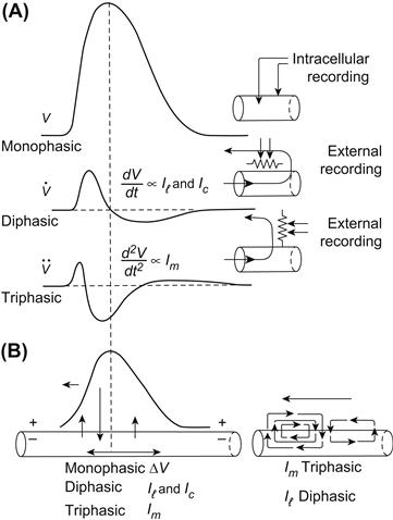
FIGURE 18.6 (A) Schematic representation of the first ( ) and second (
 ) time derivatives of the AP spike and the longitudinal and radial currents associated with the propagating spike. The first derivative (dV/dt or
  ) is proportional to the capacitive current (Ic = Cm dV/dt) and to the longitudinal (axial) current and is diphasic, having an intense forward phase and a less intense backward phase, as depicted in the diagram at the lower right. The second derivative (d2V/dt2 or
  ) is proportional to the radial transmembrane current (Im), and is triphasic, having a moderately intense initial outward phase, then a very intense inward phase (the “current sink”), followed by a least intense second outward phase, as depicted in the lower diagrams. (B) The arrows at the lower left also depict the three phases of the membrane current and the two phases of the axial current. dV/dt can be recorded externally by a pair of closely-spaced (relative to the spike wavelength) electrodes arranged parallel to the fiber axis, as illustrated. d2V/dt2 can be recorded by a pair of electrodes arranged perpendicular to the fiber axis, as depicted. The vertical dashed line indicates that when the slope of the spike goes to zero at the peak of the spike, dV/dt is zero; dV/dt is maximum at about the middle of the rising phase of the spike.
At the peak of the AP in one region of the fiber, the inside of the membrane at that region becomes positive with respect to the outside. The inside is also positive with respect to the inside cytoplasm at a region downstream from the active region. Therefore, current flows through the cytoplasm from the active region (current source) to the adjacent inactive region, then out of the fiber across the cell membrane, then through the interstitial fluid back to the active region (current “sink”) and, finally, through the membrane of the active region. This completes the closed loop for the current.
The outward current through the membrane of the inactive region produces an IR voltage drop (Ohm’s law), positive inside to negative outside. This acts to depolarize this region, because the polarity of the voltage drop is opposite to that of the RP (negative inside, positive outside). When the depolarization exceeds the threshold potential, an AP is triggered. Thus, the inactive region becomes converted to an active region. This process is repeated in each segment of fiber, thus resulting in movement (propagation) of the impulse sequentially down the fiber.
If we examine a propagating AP in the middle region of a fiber (see Fig. 18.6), we see that there is also a small backflow of current internally, coupled with a corresponding small forward flow externally, associated with the repolarizing phase of the AP. Thus, as the AP propagates down the fiber, from right to left, there is a simultaneous double flow of local-circuit current: clockwise flow associated with the rising phase of the AP and counterclockwise flow associated with the repolarizing phase of the AP.
The internal longitudinal current, sweeping past a transverse plane of the fiber, has two phases, first forward (right to left) and then reverse (left to right). The external longitudinal current also has two phases: first left to right and then right to left.
The transverse membrane current, flowing outward in a plane perpendicular to the membrane, has three consecutive phases: first outward (still passive membrane), then inward (active membrane) and, finally, outward again (still active membrane).
It is the local-circuit current flow that enables the electrocardiogram (ECG), electromyogram (EMG), electroencephalogram (EEG) and electroretinogram (ERG) to be recorded from the body surface over the tissue of interest (heart, skeletal muscle, brain and eye). The internal longitudinal current is confined to the cytoplasm of the fiber, but the external current can use whatever conducting fluid is available (e.g. the entire torso volume conductor) because of the principle that parallel resistors give a lower total resistance (or current takes the path of least resistance). Thus, this external local-circuit current causes the skin to be at different potentials, and these differences can be recorded (as the ECG, etc.).
VB Propagation Velocity Determinants
The factors that determine active velocity of propagation (θ) include: (1) fiber diameter, (2) length constant (λ), (3) time constant (τm), (4) local-circuit current intensity, (5) threshold potential and (6) temperature. Some of these factors are interrelated, such as fiber diameter and length constant (since λ is proportional to the square root of the radius) and length constant and time constant (since both have a dependence on Rm). Propagation velocity is directly proportional to length constant and inversely proportional to time constant as:
 (18.12a)
By substituting Equation 18.4a for λ and Equation 18.5a for τm, we have:
 (18.12b)
Thus, propagation velocity is directly proportional to the square root of fiber diameter or radius (a) and inversely proportional to membrane capacitance (Cm). The larger the fiber diameter, the lower the absolute longitudinal resistance of the intracellular cytoplasm (principle of resistors in parallel) and therefore the greater the amount of local-circuit current flowing longitudinally and the greater the length constant. For example, it is well known that the larger the diameter of nerve fibers, the faster they propagate (see Table 18.1). Equation 18.12b shows that if Cm can be reduced (by myelination), then θ should increase in proportion. This is discussed in Section IVC.
In addition, θ depends on the intensity of the local-circuit current, and hence on the rate of rise of the AP. The greater the AP rate of rise (max dV/dt), the greater the longitudinal current and the transmembrane capacitive current (Ic). Therefore, all other factors being constant, faster-rising APs propagate faster. The AP rate of rise depends on the density of the fast Na+ channels that carry inward current, on Cm and on temperature. Max dV/dt decreases with increased Cm, with cooling and with partial depolarization (due to the h∞ versus Em relationship discussed in the following chapter). Cooling slows the rate of all chemical reactions, particularly those with a high Q10 (activation energy), such as the ion conductance changes in activated membrane.
Finally, the threshold potential (Vth) affects propagation velocity. If the threshold were to be shifted to a more positive voltage (more depolarized), then it would take longer for a given point in the membrane to reach threshold (and explode) during propagation of an AP from upstream. A greater critical depolarization (difference between RP and Vth) would be required to bring the membrane to threshold. Therefore, propagation velocity would be slowed.
As stated earlier, some of these factors are interrelated and some actually exert opposing effects.
The foregoing discussion applies to non-myelinated nerve axons and skeletal muscle fibers. An electron micrograph of small bundles of non-myelinated nerve fibers enveloped by Schwann cells is shown in Fig. 18.7. In myelinated nerve fibers, propagation velocity is greatly increased by the myelin sheath, as discussed in the following section.
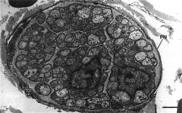
FIGURE 18.7 Electron micrograph of an autonomic nerve of mouse heart cut in transverse section. The unmyelinated axons (Ax) are arranged in small groups (bundles) that are engulfed by the cytoplasm of a Schwann cell. That is, the non-myelinated axons are embedded in, and surrounded by, a Schwann cell. Two Schwann cell nuclei (Sch) can be seen. The axon bundles are separated and surrounded by a collagenous matrix. The entire nerve is surrounded by a perineurial sheath (PN). The scale bar at lower right equals 2 μm. (Micrograph courtesy of Dr Mike Forbes, University of Virginia.)
VC Saltatory Conduction
The nerve cable has been vastly improved by the evolutionary development of myelination in vertebrates. An electron micrograph of a myelinated nerve fiber is shown in Fig. 18.8. The myelin sheath improves the cable by increasing the effective Rm by about 100-fold and decreasing the effective Cm by about 100-fold. This increases the length constant, λ. Although τm tends to increase with the increase in effective Rm (due to the myelin sheath), the decrease in Cm counteracts this effect, thus acting to hold τm almost constant. Thus, Equations 18.12a and 18.12b predict that propagation velocity should increase with myelination.
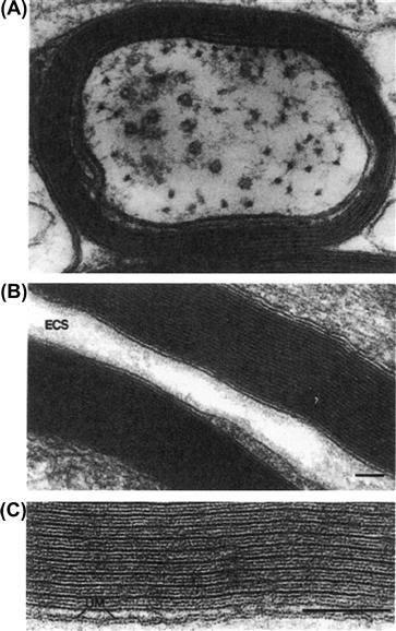
FIGURE 18.8 Myelin sheath of myelinated nerve fibers. (A) Myelinated nerve fiber in spinal cord of rat cut in cross-section. There are about seven wrappings of the Schwann cell around the axon, thus giving about 14 membranes in series with the cell membrane of the axon (axolemma). The internal mesaxon is visible at the left side (lower) of the axon and represents the beginning of the spiraling of the Schwann cell membranes (cytoplasm squeezed out) to form the myelin sheath surrounding the axon. On the upper left side, a process of an oligodendrocyte abuts on the myelin sheath. The axon shown is closely plastered up against the myelin sheath of a neighboring axon (bottom of figure). Microtubules and neurofilaments are visible in the cytoplasm of the axon. Magnification of 168 000×. (From J. Rhodin, An Atlas of Histology, Oxford University Press, New York, 1975.) (B) Higher magnification of two adjacent nerves fibers (in phrenic nerve of rat) cut in longitudinal section to illustrate an axon with a thicker myelin sheath (approx. 23 wrappings=46 membranes). Note that between the thicker (dense) lines are two thinner lines, which can be seen more clearly in (C). The extracellular space (ECS) between the two axons is labeled. The calibration bar at the lower right equals 0.1 μm. (C) Still higher magnification of a portion of one of the myelin sheaths shown in the middle panel better to illustrate the periodicity of the myelin membranes. The dense lines alternate with a pair of thin lines. The space in between the pair of thin lines is extracellular space. The dense lines represent the intracellular (cytoplasmic) region of the Schwann cell process, with the cytoplasm extruded, thus allowing the inner (cytoplasmic face) leaflets of the cell membrane of the Schwann cell to come into close contact. The outer (extracellular face) leaflets of the Schwann cell membrane are seen as the thin lines. Thus, each cell membrane has the appearance of a double line, representing the hydrophilic surfaces of the cell membrane; the hydrophobic region of the membrane is the clear region between the dense line and the contiguous thin line on either side. UM; unit cell membrane. The scale bar on the lower right represents 0.1 μm. (Micrographs (B) and (C) courtesy of Dr Mike Forbes, University of Virginia.)
One consequence of myelination, therefore, is that propagation velocity is greatly increased (see Table 18.1). Another consequence is that the energy cost of signaling is greatly decreased, because passive ion leaks are limited and active current losses are restricted to the small nodes of Ranvier, which are spaced relatively far apart. An electron micrograph of a node of Ranvier is shown in Fig. 18.9. At each node, the length of exposed (naked) cell membrane is very short. The node forms an annulus around the entire perimeter of the fiber. The internodal distance is about 0.5–2.0 mm (depending on fiber diameter) and the width (length) of each node is only about 0.5–3 μm. Therefore, the degree of energy-requiring active ion transport (Na+-K+ and Ca2+) required to maintain the steady-state ion distributions and to hold the system in a state of high potential energy is greatly reduced. For example, the amount of Na+ gained and K+ lost per impulse is reduced as a result of myelination. The low rate of oxidative metabolism in myelinated fibers reflects this lowered energy requirement.

FIGURE 18.9 Electron micrograph of one node of Ranvier in a single myelinated nerve axon of rat sciatic nerve cut in longitudinal section. Dark myelin bordering the axon on each side is interrupted near the middle of the micrograph, leaving the neuronal cell membrane nude of myelin at the node region. However, cytoplasmic processes of the Schwann cells cover the nodal membrane. Collagenous fibrils of the endoneurium are visible at the region of the node. The myelin tapers and thins as it approaches the node and there is a frayed appearance caused by the successive laminae of the myelin sheath terminating as cytoplasmic swellings. The axoplasm contains neurofilaments and microtubules. Magnification of 9000×. (From J. Rhodin, An Atlas of Histology, Oxford University Press, New York, 1975.)
The myelin sheath is produced by the wrapping of the Schwann cell repeatedly around the nerve fiber in a spiral, forming 20–200 wrappings, depending on axon diameter. That is, the larger axons have a thicker myelin sheath. For the purpose of our discussion, we will assume an average of 100 wrappings. The myelin sheath covers the nerve axon as a coat sleeve and is interrupted at each node. The cytoplasm of the Schwann cell in the region of the myelin sheath is nearly completely extruded during its formation, so that the sheath consists essentially of 100 cell membranes stacked in series. Because resistors in series are added to calculate the total resistance, the effective transmembrane resistance is increased 100-fold, but the effective capacitance is reduced 100-fold (because the total capacitance of capacitors in series is calculated like resistors in parallel). Since λ is directly proportional to  λ is increased accordingly. The greater λ and lowered Cm increase θ.
Myelinated nerves usually have an optimal amount of myelin, which is an amount such that the ratio of diameter of axon cylinder (naked axon) to total fiber (including myelin sheath) is about 0.6–0.8. Assuming a maximal total diameter feasible (the body must pack many circuits within a limited space, e.g. sciatic nerve bundle), a greater fraction of myelin, by infringing on the diameter of the axis cylinder, would raise ri too high, causing θ to decrease. Thus, there are two opposing factors in determining the degree of optimal thickness of the myelin sheath. The more the myelin, the greater the decrease in Cm and increase in effective Rm, but then the smaller diameter of the axis cylinder causes a higher ri.
In saltatory conduction (Latin saltare, to jump), the impulse jumps from one node to the next. The internodal membrane does not fire an AP. This is due to two reasons: (1) the internodal membrane is much less excitable (e.g. much fewer fast Na+ channels); and (2) the depolarization of the neuron cell membrane at the internodal region is only about 1/100th of that at the node. The latter occurs because the IR voltage drop across the internodal cell membrane is only 1/100th of that across the entire series resistance network (neuron cell membrane plus 100 layers of Schwann cell membrane) (Kirchhoff’s laws dealing with voltage drops across resistors in series). Even though the internal potential in the internodal region swings positive (e.g. to +30 mV) when the adjacent nodes fire, the potential at the outer surface of the internodal membrane also swings nearly as positive (e.g. to +29 mV). Therefore, the depolarization of the neuronal membrane at the internode is only about 1 mV, which is well below threshold and so the internodal membrane does not fire. The potential that controls the membrane conductances (activates the voltage-dependent ion channels) is the pd (potential difference) directly across the membrane and not the absolute potential on either side.
As stated previously, the internodal membrane has only a few fast Na+ channels, whereas the nodal membrane has a very high density. Since the cell membrane is fluid and proteins can diffuse (float) laterally in the lipid bilayer matrix, what keeps the fast Na+ channel proteins confined (at high density) in the nodal region? There are special anchoring proteins (e.g. ankyrin) that anchor the ion channel proteins to the cytoskeletal framework, thus preventing their lateral movement into the internodal membrane.
The effect of myelin and saltatory propagation is to make propagation much faster. For example, a 20-μm-diameter myelinated nerve fiber conducts even faster than a 700-μm (0.7 mm) diameter non-myelinated nerve fiber (e.g. the giant axon in squid, lobster, earthworm): 120 m/s versus 25–50 m/s. Thus, invertebrates, to achieve fast conduction in some essential circuits, must resort to giant neurons, resulting in a lower ri and hence fast conduction. Because of space/size limitations, only a few critical neurons can be made giant in diameter. In vertebrates, on the other hand, a large fraction of the nerve fibers in the peripheral nerves are myelinated for fast propagation.
We saw earlier that, in non-myelinated axons and skeletal muscle fibers, θ should vary with the square root of the cell diameter or radius (a0.5). In myelinated axons, θ varies with the first power of the cell radius (a1) because θ varies with λ2 as indicated by:
 (18.13)
The dependence of conduction velocity on diameter of nerve fibers is summarized in Table 18.1.
VD Wavelength of the Impulse
We can calculate the wavelength of the AP, which is the length of the axon simultaneously undergoing some portion of the AP. The wavelength is equal to propagation velocity (θ) times the duration of the AP (APD100); thus,
 (18.14)


Note the similarity of this relationship to that for the wavelength of an electromagnetic radiation: wavelength = velocity of light/frequency of the radiation. The reciprocal of frequency is the period (duration of one cycle). The wavelength in a large myelinated nerve axon is about 12 cm: 120 m/s × 1.0 ms. In a skeletal muscle fiber, it is about 1.8 cm (6 m/s × 3.0 ms). In a smooth muscle bundle, the wavelength is only about 1.5 mm (5 cm/s×30 ms).
VI External Recording of Action Potentials
VIA Monophasic, Diphasic and Triphasic Recording
As discussed previously, local-circuit currents accompany the propagating AP in each fiber. The intracellular and extracellular longitudinal currents are diphasic; i.e. initially they travel in the forward direction intracellularly and then in the reverse direction. The forward direction current is intense (high current density) and the reverse direction current is weak (low current density). The transmembrane radial currents are triphasic; i.e. the first phase is outward (moderate intensity), the second phase is inward (high intensity) and the third phase is outward (low intensity). The first phase (outward) gives rise to the passive exponential foot of the AP and is due to the passive cable spread of voltage and current. The second phase (inward) corresponds to the large inward fast Na+ current, which occurs during the later portion of the rising phase and peak of the AP. The third phase (outward) corresponds to the net outward current (K+), which occurs during the repolarizing phase.
These longitudinal and radial currents can be recorded by suitably-placed external electrodes. The extracellular longitudinal currents can be recorded by two electrodes (bipolar) placed close together along the length of the fiber. If the interelectrode distance is short (relative to the wavelength), an approximate first (time) derivative of the AP is obtained (see Figs. 18.6 and 18.10C). The extracellular radial currents can be recorded by two electrodes placed close together in a plane perpendicular to the fiber axis. This gives an approximation of the second (time) derivative of the AP (see Fig. 18.6).
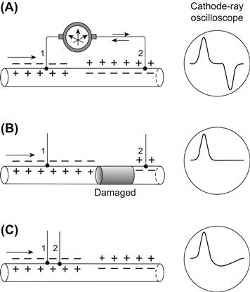
FIGURE 18.10 Diagram of the waveforms that would be recorded externally during propagation of an AP in a single fiber. (A) When the two electrodes are far apart (relative to the AP wavelength), a diphasic recording is obtained, with the two phases being symmetrical and separated by an isopotential segment. The two phases are due to the current flow through the voltmeter recorder being first in one direction and then in the opposite direction. (B) If the fiber between these two electrodes is damaged (e.g. by crushing) or depolarized (by elevated [K+]o), so the AP cannot sweep past the second electrode (2), then this second phase is prevented and the recording is monophasic. (C) If the two electrodes depicted in (A) are brought progressively closer, then the isopotential segment would shorten and disappear. If electrode 2 is brought very close to electrode 1, so that the interelectrode distance is short relative to the wavelength, then the second phase is smaller than the first phase, and the record resembles the first derivative of the true AP.
The internal axial currents are confined to the cytoplasm, whereas the external longitudinal currents can use the entire interstitial fluid space of the nerve bundle or muscle or even the entire torso (volume conductor), since current takes the path of least resistance (resistors in parallel). As mentioned in Section IVA, this allows the recording of the ECG from the body surface and the EMG from the skin overlaying an activated skeletal muscle. The ECG and EMG consist essentially of diphasic potentials, reflecting the external longitudinal currents during propagation of APs.
When the two external electrodes are placed far apart (with respect to the wavelength) along a nerve or muscle fiber, the diphasic recording has two phases that are about equal (Fig. 18.10A). The proximal electrode records the wave of negativity (associated with the propagating AP) first and then returns to isopotential. When the wave reaches the second electrode, the wave is recorded by it in reversed polarity (because current flow through the voltmeter is reversed). If the AP were now prevented from reaching the second (distal) electrode by crushing this region of the fiber or elevating [K+]o to depolarize it, then a monophasic recording would be obtained (Fig. 18.10B). This monophasic recording would most resemble the true AP recorded by a microelectrode impaled into a fiber to record the transmembrane potential, but would be much smaller in amplitude.
VIB Compound Action Potential
When one records the APs externally, the records are graded and not all-or-none. (In contrast, in the case of the true APs recorded intracellularly from single fibers [see following chapter], the APs are all-or-none.) That is, the signal recorded becomes larger and larger, up to a maximum amplitude as the intensity of stimulation is increased. This is the so-called compound action potential. It is graded because, as a greater and greater fraction of the fibers are activated, the external longitudinal currents associated with the all-or-none AP in each fiber cut across the recording electrodes, thereby producing a larger signal. The AP in each individual fiber is always all-or-none. The amplitude of the signal is determined by the resistance between the electrodes multiplied by the amount of current flowing through this resistance (V = IR). The recording of compound action potentials is diagrammed in Fig. 18.11.
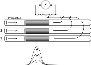
FIGURE 18.11 Diagram of a compound action potential in an isolated nerve trunk, such as the frog sciatic nerve, recorded externally by a pair of longitudinal electrodes. The voltmeter (oscilloscope) records the voltage (IR) drop across the resistance (fluid) between the two electrodes. If only fiber 1 is activated, the current passing between the electrodes is small and the voltage recorded is small. If fiber 2 is simultaneously activated with fiber 1, then the amount of current is doubled and the voltage is doubled. When all three fibers are simultaneously activated, the current is tripled, and the voltage is tripled. Therefore, the externally recorded compound action potential is graded because it reflects the electrical activity of numerous fibers, each of which produces an all-or-none AP.
The compound action potentials can be demonstrated by recording the EMG from a human subject when one electrode is placed on the skin of the ventral forearm and the other (reference) electrode on the wrist of the same arm. Then, as the subject voluntarily produces stronger and stronger contraction to flex the hand, the electrical signals picked up become greater and greater in amplitude and frequency. The amplitude becomes larger because more muscle fibers are simultaneously activated. This is known as fiber recruitment. The frequency also increases, because the motor nerves fire at a higher frequency, causing the muscle fibers to fire at a higher frequency and thus producing a more powerful tetanic contraction.
Appendix 1 Additional Discussion of Input Resistance and Impedance
Because:  (Equation 18.4a), Equation 18.9 can be given as:
 (18A.1)
and Equation 18.11 can also be given as:
 (18A.2)
Thus, input resistance is proportional to  This indicates that the higher the longitudinal resistance of the fiber’s axoplasm (or myoplasm), which is a function of the resistivity of the axoplasm and fiber diameter, and the higher the membrane resistance, the higher the input resistance. The input resistance also can be calculated from the electrical equivalent circuit for a cable.
The input impedance can also be given in terms of Rm and Ri, the specific resistance of the cell membrane and resistivity of the axoplasm, respectively. Since Rm = 2πarm and Ri = πa2ri, then Equation 18.12 can be converted to:
 (18A.3a)
 (18A.3b)
Thus, the input resistance is directly proportional to the square root of the membrane specific resistance and the resistivity of the axoplasm and inversely proportional to the square root of the fiber radius raised to the third power.
Calculation of the input impedance (Zin) is more complicated because it also depends on the membrane capacitance (Cm) and on the frequency (f) of the alternating current (AC) used. According to Katz (1966), the input impedance of a long fiber (current injected at one end) is given by:
 (18A.4)

A discussion of the AC length constant (λAC) is beyond the scope of this chapter.
Appendix 2 Propagation in Cardiac Muscle and Smooth Muscles
AI Background
Chapter 18 discusses propagation in cells that are long cables, such as nerve fibers and skeletal muscle fibers. Propagation is more complex in tissues composed of assemblies of short cells, such as cardiac muscle and visceral smooth muscles. These short cells may be considered to be short or truncated cables. In such a truncated cable cell, its true length constant λ is much longer than the cell’s length. Therefore, there is relatively little voltage fall-off (decay) over the length of each cell. It follows that the entire cell undergoes an action potential (AP) nearly simultaneously. Yet propagation velocity θ is much slower in cardiac muscle (ca. 0.5 m/s) and smooth muscles (ca. 0.05 m/s) than in skeletal muscle (ca. 5–6 m/s) or non-myelinated nerve fibers (ca. 2 m/s). Part of the reason for the slower θ concerns fiber diameter (i.e. diameter of cardiac muscle fiber is about 15 μm compared to about 60 μm for skeletal muscle fibers). Equation 16b in Chapter 18 indicates that in a simple cable, θ is a function of  (where a is the fiber radius). The fact that skeletal muscle also has a much higher max dV/dt (rising phase of the AP) than cardiac muscle and smooth muscle is another factor that contributes to the lower than expected θ in cardiac muscle and smooth muscle. The max dV/dt in cardiac muscle is ca. 200 V/s and in smooth muscle ca. 5 V/s, as compared with skeletal muscle ca. 600 V/s. In addition, the higher the extracellular resistance, which depends on the tightness of packing of the fibers in the muscle tissue, the slower the velocity.
Another factor that determines velocity in cardiac muscle and smooth muscle is the high resistance of the junctional membranes (the intercalated disk membranes in the case of cardiac muscle). It is still controversial as to exactly how high the junctional resistance is. When gap junctions are present, the gap junction channels span the intercellular junction, and so serve to lower the cell-to-cell resistance (see chapter on gap junctions). However, the hearts of lower vertebrates (e.g. fish, amphibians, reptiles) either have no gap junctions or they are very sparse and tiny. In addition, even parts of mammalian hearts and some visceral smooth muscles (e.g. longitudinal muscle layer of intestine) do not appear to contain gap junctions. If so, another mechanism may be involved for cell-to-cell propagation in those muscles in which there is a virtual absence of gap junctions. One of the mechanisms proposed is known as the electric field model (Sperelakis and Mann, 1977; Sperelakis et al., 1979). This mechanism is discussed in this appendix.
Since the short cardiac muscle cell shows no voltage decay, the entire length of the cell should undergo the AP nearly simultaneously (i.e. nearly infinite propagation velocity within each cell). Yet, the overall propagation velocity in the tissue is relatively slow. Clearly, a large time delay must occur at each cell junction. In fact, most of the propagation time is consumed at the cell junctions. This has been demonstrated experimentally. Propagation in cardiac muscle has been shown to be actually discontinuous or saltatory in nature (Spach et al., 1981; Cole et al.,1988; Sperelakis et al., 1983). Therefore, the presence of a few gap-junction channels is insufficient to reduce the junctional resistance enough to allow a chain of cells to behave as a simple cable. This relatively high junctional resistance may have relevance to heart block and fibrillation.
AII Some Experimental Facts
Some of the key experimental facts relevant to the transmission of excitation from one cell to the next in cardiac muscle and visceral smooth muscle can be summarized as follows. These tissues can be enzymatically separated into their individual cells and the individual single cells are viable and functional. Gap junctions are absent in the hearts of lower vertebrates and in some regions of mammalian hearts, as well as in some visceral smooth muscles, as stated previously. The length constant λ of cardiac muscle and smooth muscle tissues, when measured properly, is relatively short, i.e. less than 0.3 mm (i.e. not much more than about one cell length). The input resistance (Rin) of cardiac muscle and smooth muscle, when measured properly, is relatively high, about 5–40 MΩ. The short λ and high Rin suggest that the cells are not profusely connected by low-resistance pathways (e.g. by gap-junction channels). Thus, even when gap junctions are present, the junctional membranes still constitute a substantial barrier to current flow from one cell to the next (Tarr & Sperelakis, 1964).
As stated above, there is almost no voltage decay in a single cell and the entire cell fires an AP nearly simultaneously. Therefore, most of the propagation time is consumed at the cell junctions and propagation in these tissues is a discontinuous process. Propagation velocity in cardiac muscle and smooth muscle is slower than what can be accounted for by the smaller fiber diameter and lower max dV/dt. The cell-to-cell transmission process is quite labile, somewhat like that in synaptic transmission.
Considerable data have been published concerning the degree of spread of electrotonic current between neighboring cells in cardiac muscle and visceral smooth muscles. Only one example is presented here for frog cardiac (ventricular) muscle. In these experiments, electrode 1 was used to record voltage and to inject current (using a Wheatstone bridge circuit), whereas electrode 2 recorded voltage only. As illustrated in Fig. 18A.1, using a pair of microelectrodes whose tips were spaced 11 μm apart, in some double impalements there was no electrotonic current spread between the two electrodes (e.g. panel A in Fig. 18A.1), whereas in other impalements there was substantial spread of current (e.g. panel B). In one unusual case (panels C, D), the double impalement first showed good spread (i.e. interaction) between the electrodes (C), but then due to muscle contraction, one electrode left that cell and impaled a neighboring cell having a normal RP (right portion of panel C); then there was no significant interaction between the two electrodes residing in neighboring cells (D). In the impalements in which there was substantial interaction between the electrodes (e.g. panels B, C), it was proposed that the two electrodes had impaled the same cell (e.g. both electrodes recorded low RPs (perhaps due to damage caused by the two electrodes impaling one cell). In the impalements in which there was little or no interaction (e.g. panels A, D), it was proposed that the electrodes had impaled neighboring cells. This interpretation is most clear in panel D, in which the two electrodes recorded markedly different RPs. Thus, there appears to be little or no spread of current between neighboring cells in frog cardiac muscle. If so, then propagation of excitation must occur by some other means.
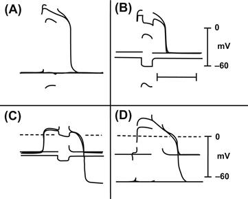
FIGURE 18A.1 Three typical experiments (A, B and C, D) measuring the spread of electrotonic current between two closely spaced intracellular microelectrodes in intact frog ventricular trabeculae at rest and during the plateau of the action potential. The interelectrode distance was 11 μm. Rectangular hyperpolarizing current pulses (approx. 150 ms in duration) were applied. Two successive sweeps of the oscilloscope are superimposed in each panel. (A) Interaction at rest and during the plateau was nearly 0%. Capacitive transients are only seen on the trace from electrode 2, whereas a large maintained hyperpolarization occurred at electrode 1. (B) In another impalement in which the cell was injured by the two electrodes, the resting potential was low and the degree of interaction was high. (C, D) In another impalement in which the cell was damaged, the resting potential was low and the degree of interaction was high (electrode I deflection not shown because of bridge imbalance). The contraction accompanying the action potential caused one of the electrodes to become dislodged from that cell and penetrate into a neighboring cell that had a normal resting potential; the degree of interaction then became nearly zero. (Reproduced with permission from Tarr, M. and Sperelakis, N. (1964). Am J Physiol. 207, 691-700.)
AIII Electric Field Model
AIIIA Electric Field Effect
Sperelakis and colleagues developed an electric field (EF) hypothesis for propagation of APs in cardiac muscle for situations in which there were no functioning gap junction channels. A computer simulation model for cell-to-cell propagation in cardiac muscle was developed and progressively improved since the mid-1970s (Sperelakis and Mann, 1977; Sperelakis et al., 1983; Sperelakis, 1987; Picone et al., 1991). The model allows electrical transmission to occur between adjacent excitable cells by means of the EF effect in the very narrow junctional cleft between the contiguous cells (Sperelakis and Mann, 1977). This EF model does not require low-resistance channels (gap junctions) between cells. The major requirements of the model are that the pre- and post-junctional membranes (pre-JM and post-JM) be ordinary excitable membranes and that these membranes be very closely apposed to one another (i.e. the junctional cleft be very narrow, about 10 nm). When the pre-JM fires, the cleft between the cells becomes negative with respect to ground (the interstitial fluid surrounding the cells) and this negative cleft potential (about −40 mV) acts to depolarize the post-JM by an equal amount (namely, 40 mV) and brings it to threshold. (The inner surface of the post-JM remains at nearly constant potential with respect to ground.) This, in turn, brings the surface membrane of the post-junctional cell to threshold.
Figure 18A.2A illustrates propagation of an AP along a chain of 10 cells by the EF effect. In this computer simulation of cardiac muscle, propagation of overshooting APs occurred at a constant velocity of 32 cm/s and the maximum rate of rise of the AP averaged 209 V/s. As can be seen, the upstroke of each AP exhibited a break or step, reflecting the junctional transmission process.
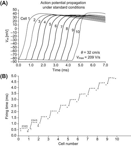
FIGURE 18A.2 Electric field model for propagation in cardiac muscle using a computer simulation. (A) Successful propagation of an AP at constant velocity along a chain of 10 cells under standard conditions. Propagation velocity was 32 cm/s; max dV/dt was 209 V/s. Note the small step, or prepotential, on the AP upstroke. (B) Plot illustrating that junctional delays occupy most of the propagation time. Firing time for an AP to spread along the chain of 10 cells under standard conditions (corresponding to part A) is plotted against distance. Within each cell, the units are numbered 1 through 6 from left to right, 1 corresponding to the post-JM (input), 2–5 the surface membrane and 6 the pre-JM (output). The AP travels along the surface membrane at a high velocity. At the junctions between cells, there is a significant conduction delay as the AP “jumps” across the cleft. This clearly demonstrates the discontinuous nature of AP propagation. (Adapted with permission from Figs. 2 and 3 of Sperelakis, N., Ortiz-Zuazaga, H. and Picone, J.B. (1991). Innov Tech Biol Med. 12, 404-414.)
In the model, a plot of propagation time as a function of distance along a chain of cells has a staircase shape, indicating that almost all propagation time is consumed at the cell junctions and that excitation of each cell is virtually instantaneous (Picone et al., 1991; Sperelakis et al., 1983) (see Fig. 18A.2B). In this figure, it can also be seen that the prejunctional membrane fires a fraction of a millisecond before the surface membrane of the same cell, as required by the EF model. Propagation was found to be strongly dependent on radial cleft resistance (Rjc) and the junctional membrane properties. There was an optimal Rjc for maximum propagation velocity under any given conditions. This model is consistent with many experimental facts about propagation in cardiac muscle, and provides an alternative mechanism for AP propagation that does not require low-resistance pathways to transfer excitation directly between adjacent cells. The EF model can also account for the fact that propagation in cardiac muscle is actually discontinuous or saltatory in nature (Spach et al., 1981).
AIIIB High Density of Fast Na+ Channels at Intercalated Disks
For this mechanism to work efficiently, there is a requirement for the prejunctional membrane to fire an AP a fraction of a millisecond before the contiguous surface membrane (Sperelakis and Mann, 1977). That is, the prejunctional membrane should be more excitable than the surface membrane, which would cause it to reach threshold first. This situation would be achieved if there were a greater density of fast Na+ channels in the junctional membranes (intercalated disks, IDs) than in the contiguous surface membranes (Sperelakis and Mann, 1977). This would make the IDs more excitable and give them a lower threshold than the surface membrane. To examine this possibility, a polyclonal antibody raised against fast Na+ channels (from rat brain) was used to immunolocalize the fast Na+ channels in rat atrial and ventricular tissues. In immunofluorescence examination, intense labeling was observed associated with the IDs of both atrial and ventricular cells (Ferguson, D., Sperelakis, N., and Angelides, K. J., 1991 (unpublished) (Fig. 18A.3). This fluorescence was more intense than that of the cell surface membrane. These findings are in agreement with results reported by Cohen and Levitt (1993).
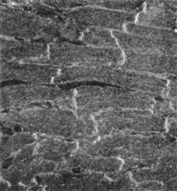
FIGURE 18A.3 Immunofluorescence localization of Na+ channels in adult rat cardiac muscle (ventricle) using polyclonal antibody to the fast Na+ channels of rat brain. The antibody is most densely localized at the cell junctions (intercalated disks), but also stained the surface cell membrane. These results suggest that the intercalated disks are highly excitable membranes, even more excitable than the surface cell membrane, consistent with the requirement of the electric field model for propagation between cells not connected by low-resistance tunnels (gap junction connectons). (From Ferguson, D., Sperelakis, N. and Angelides, K.J., unpublished observations.)
Therefore, it is likely that, not only are fast Na+ channels present at the ID membranes, they are present in a higher concentration (density) than in the surface cell membrane. A higher density of fast Na+ channels in the junctional membrane would cause it to have a lower threshold than the surface membrane and so it would reach threshold and discharge first. This would be analogous to the initial segment of the axon of the anterior horn neuron having a lower threshold and therefore discharging before the soma or proximal dendrites (where the excitatory synapses are actually located). Consistent with these findings, it was reported that K+ channels are also localized at the IDs (Mays et al., 1995). Therefore, the EF model is a plausible mechanism for cell-to-cell transmission of excitability in cardiac muscle and in visceral smooth muscle. EF effects may also occur between closely spaced contiguous neurons in the central nervous system.
AIV Electronic Model for Simulation of Propagation
Sperelakis and colleagues (1990) constructed an electronic model to simulate an excitable membrane and this model was used to examine propagation. Four such circuits were successfully made to interact with one another through capacitive coupling to simulate propagation over four cells. Adjustment of one parameter either slightly depolarized and caused repetitive spontaneous APs, or hyperpolarized slightly and depressed excitability, causing partial block (e.g. 2:1, 3:1, 4:1) or complete block of propagation from cell to cell at the cell junctions. When four such cells were connected head to tail in a closed loop, re-entry of excitation occurred and could keep going for many seconds before dying out (due to failure at one of the labile junctions).
In a subsequent study (Ge et al., 1993), 12 such units were arranged to model two adjacent cells: four units for each surface membrane and one for each junctional membrane. The first unit was stimulated to threshold and AP propagation spread over the two cells was recorded (Fig. 18A.4). In this example, the first cell was set to be spontaneously active and fire a spontaneous cardiac-like AP. All four surface-membrane units in cell 1 (U2, 3, 4, 5) fired an AP nearly simultaneously. However, there was a short delay (e.g. ca. 0.5 ms) in the firing of the unit (U6) representing the prejunctional membrane (at the ID). Firing of U6 led to the firing of all units (U7, 8, 9, 10,11, 12) of cell 2 after a junctional delay of about 2 ms. The firing of the pre-junctional membrane (U6) drove inward hyperpolarizing current through the post-junctional membrane (U7) and outward depolarizing current through the other units (U8, 9, 10, 11, 12) of cell 2 due to current flow (prior to triggering an AP). The time delay was 1–2 ms at the junction. Raising the effective coupling resistance (Rc) between the two cells and lowering Cj increased the conduction delay. Propagation was blocked when Rjc, the radial shunt resistance at the cell junction, was below 10 KΩ. The post-JM (unit 7) only fired an AP when unit 6 was active, reflecting the EF effect across the junction. Both local-circuit current and the EF effect play roles in the transfer of excitation in this model.
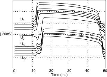
FIGURE 18A.4 Action potentials produced in an electronic model of two heart cells with a cell junction between them. There were six excitable-circuit units in each cell: four representing the surface cell membrane (U2, 3, 4, 5 and U8, 9, 10, 11) and one for each junctional membrane (U1, 6 and U7, 12). The parameters in the first cell (cell 1) were adjusted so that it fired spontaneously in response to pacemaker potential depolarization. Note the nearly simultaneous firing of all units in cell 1 and, after a slight junctional delay time, the nearly simultaneous firing of all units of cell 2. (Reproduced with permission from Fig. 5A of Ge, J., Sperelakis, N. and Ortiz-Zuazaga, H. (1993). Innov Tech Biol Med. 14, 404-420.)
AV PSpice Model for Simulation of Propagation
PSpice is an electrical engineering software program for circuit design and analysis. The appropriate differential equations are built into PSpice. We recently modeled propagation of APs of cardiac muscle using the PSpice program (Sperelakis and Ramasamy, 2002). Like the mathematical simulation and the electronic model, we found that the EF developed in the junctional clefts (negative VJC) was large and sufficient to allow transfer of excitation to the contiguous cell, without the requirement of gap-junction (gj) channels. In the absence of gj channels, transmission of excitation from one cell to the next occurs by means of the intense EF that develops in the narrow junctional cleft (IDs) when the pre-junctional membrane fires an AP. This cleft potential is negative (with respect to ground (interstitial fluid bathing the cells)), and thus acts to depolarize the post-junctional membrane to its threshold potential. This causes the surface sarcolemma of the postjunctional cell to fire an AP and the process is repeated at the next junction. For this EF mechanism to work, the pre-junctional membrane must fire slightly before the surface sarcolemma of the pre-junctional cell (Sperelakis and Mann, 1977). The fact that the density of fast Na+ channels is greater at the ID membranes than in the surface sarcolemma (Sperelakis N., 1995; Cohen SA and Levitt LK, 1993) means that the excitability of the junctional membranes should be greater than that of the surface sarcolemma.
The myocardial cells were assumed to be cylindrical in shape, 150 μm in length and 16 μm in diameter. The cleft width of the cell junctions (IDs) was assumed to be 100 Å. Each cell was simulated by four basic circuit units; two for the surface sarcolemma and one for each junctional membrane at the two ends of the cell (Fig. 18A.5). The cell junctions contained a transverse resistance, the radial resistance of the junctional cleft (RJC). The standard value used for RJC was 25 MΩ (two 50 MΩ resistors in parallel). The basic units were connected internally by the intracellular longitudinal resistance (ri) and externally by the extracellular resistance (RO). The chain of cells was assumed to be bathed in a large volume of Ringer solution connected to ground. The values of the capacitive and the resistive elements in each basic unit were set to reflect an input resistance of 20 MΩ and input capacitance of 100 pF for the individual cells and the junctional units were prorated, based on relative areas represented. At rest, the resistance of K+ compared to Na+ was set to give RPs of −80 mV. During excitation, the APs overshot to +34 mV.
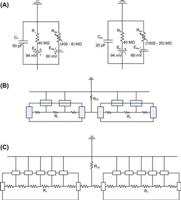
FIGURE 18A.5 (A) Depiction of the basic circuit components in the PSpice model representing a patch of surface membrane of a myocardial cell and a patch of junctional membrane. (B) Four units/cell, two in surface membrane and one in each of the two junctional membranes at the ends of the cell. (C) Seven units/cell.
To make the circuit as simple as possible, all other types of ion channels were not entered. We focused only on those channels that set the RP and predominate during the rising phase of the AP. That is, we only wanted to inscribe the rising phase of the APs in a chain of cells to study the mechanism of longitudinal propagation. The longitudinal resistance in each junctional cleft was calculated to be 14 Ω (see Fig. 18A.5C). Increasing the longitudinal cleft resistance over a very wide range had no effect on propagation velocity, because there is almost no local-circuit current across the cell junctions. A shunt resistance (Rgj, resistance of the gap junction channels) was placed across each cell junction, i.e. from one cell interior to the next (Fig. 18A.6). It was assumed that each gj-channel had a conductance of 100 pS, so Rgj was 100 MΩ when 100 gj-channels were inserted. The possibility that the gj-channels are rectifying was ignored for the present purposes. In the current presentation, the data with variation in Rgj are not given.
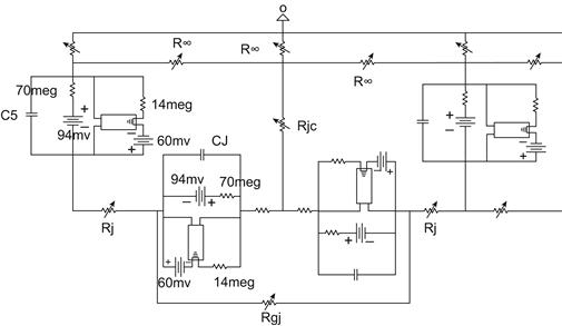
FIGURE 18A.6 A typical cell junction of circuit used for PSpice simulation of propagation of action potentials. A gap-junction shunt resistance (Rgj) is inserted across the cell junction and is in parallel with the electric field (EF) mechanism.
A stimulating current pulse was applied to the inside of unit 1 of cell 1. The values for the rectangular current pulse were 0.50 ms duration and 0.5 nA amplitude. The longitudinal average propagation velocity (θ) was calculated from the measured total propagation time (TPT), assuming a cell length of 150 μm.
The basic response of the circuit for the six-cell chain under standard conditions is illustrated in Fig. 18A.7. In this experiment, a rectangular current pulse was applied to interior of cell 1 at 0 time. The voltages directly across each of the 42 units (7 U/cell × 6 cells) and the voltage across RJC (the cleft potential) were measured.
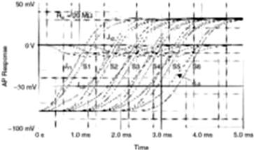
FIGURE 18A.7 Staircase propagation and firing sequences. Absence of gap junctions. Graph plots total propagation time (TPT) as a function of distance along the six-cell chain in membrane units. Total of 42 units: 7 U/cell × 6 cells. Each cell is assumed to be 150 μm long. The surface membrane of each cell is represented by five units and the two junctional membranes by one unit each. The units were numbered consecutively: 1–7 (cell 1), 8–14 (cell 2), 15–21 (cell 3), 22–28 (cell 4), 29–35 (cell 5) and 36–42 (cell 6). The junctional units fired before the surface units. Taken from Sperelakis and Ramasamy, 2002.
The rising phase of the AP response in each of the six cells can be seen. Because the five surface units in each cell fired virtually simultaneously, only three voltage traces can be seen for each cell: (a) post-JM, (b) pre-JM and (c) surface membrane. The RP of the cells was −80 mV and the AP overshoot potential was +34 mV (see Fig. 18A.7), thus giving an AP amplitude of 114 mV. The cleft potential went from 0 mV at rest to a peak of about −12 mV during excitation of the pre-JM in each cell (see Fig. 18A.7). The maximum rate of rise of the APs (max dV/dt) was about 110 V/s, the junctional delay time was about 0.3–0.6 ms and propagation velocity (θ) was about 30 cm/s. In general, the transmission delay was reduced when RJC and the cleft potential were increased and when Cj and Cs were decreased. Total propagation time (TPT) was measured between when the APs of the first cell and last cell crossed a Vm of −20 mV.
The firing sequence of the seven units of each cell is shown in Fig. 18A.8. As can be seen, in cell 1, the pre-JM (unit 7) fired before the post-JM (unit 1), which fired before the surface units (units 2–6). As stated earlier, all surface units fired virtually simultaneously. The lead time of the pre-JM became less and less in cells 2–6. This behavior pattern of the pre-JM (right end of cell) firing slightly before the post-JM (left end of cell) was also observed in the mathematical model (Picone et al., 1991). The graphic plot of propagation time as a function of distance along the chain of six cells also illustrates the staircase propagation (Fig. 18A.8). That is, the shape of the plot is like a staircase. The flat part of each step represents the long surface membrane of each cell. The sharp rise of each step represents the very short (e.g. 100 Å) cell junction gap. The overall propagation time consists almost entirely of the junctional delay times summed. That is, almost all of the propagation time is due to the junctional transmission process. The surface sarcolemma along the cell’s entire length fires simultaneously.
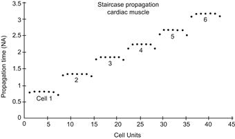
FIGURE 18A.8 Action potential (AP) responses of the six-cell chain of myocardial cells. Absence of gap junctions. At −50 mV, the first trace (of each group of three) is the post-JM (left end of cells), whereas at −10 mV, the leading trace is the pre-JM (right end of cells); i.e. the first two traces criss-cross between −40 and −20 mV). Thus, the post-JM starts to depolarize first because of the cleft potential, but the pre-JM on the far end of the cell reaches the overshoot potential first. The surface membrane units (S1–S6) fire last. Taken from Sperelakis and Ramasamy, 2002.
The cleft potential occurs during the rising phase of the AP in the pre-JM. The shape of the cleft potential is an approximation of the first time derivative of the AP upstroke (see Fig. 18A.5). In general, the cleft potential is larger when RJC is increased and when Cj and Cs are decreased. When RJC was increased from the standard 20 MΩ to 50 MΩ and 100 MΩ, the cleft potential increased from −12 mV to −27 mV and to −47 mV. The cleft potential instantly depolarizes the post-JM by an equal amount because of its patch-clamp-like action. The amplitude of the depolarization (step) on the rising phase of the AP of the post-JM is proportional to the amplitude of the cleft potential. The value of RJC for minimum junctional delay, and hence maximal propagation velocity, had a broad optimum of 20–30 MΩ. The value of RJC reflects the degree of closeness of the two junctional membranes.
In summary, it was found that propagation of excitation can occur by the EF mechanism alone, even when the excitability of the cells was low. Therefore, the EF mechanism alone can account for propagation of excitation in cardiac muscles that do not possess gap junctions. In those cases in which gap junctions do exist and are functioning, the EF mechanism would act in parallel and thereby increase the safety factor for conduction.
BIBLIOGRAPHY
1. Cohen SA, Levitt LK. Partial characterization of the rHl sodium channel protein from rat heart using subtype-specific antibodies. Circ Res. 1993;73:735–742.
2. Cole KS. Membranes, Ions and Impulses: a Chapter of Classical Biophysics. Berkeley: University of California Press; 1968.
3. Cole WC, Picone JB, Sperelakis N. Gap junction uncoupling and discontinuous propagation in the heart: a comparison of experimental data with computer simulations. Biophys J. 1988;53:809–818.
4. Ge J, Sperelakis N, Ortiz-Zuazaga H. Simulation of action potential propagation with electronic circuits. Innov Tech Biol Med. 1993;14:404–420.
5. Katz B. Nerve, Muscle, and Synapse. New York: McGraw-Hill; 1966.
6. Mann Jr JE, Sperelakis N, Ruffner JA. Alterations in sodium channel gate kinetics of the Hodgkin-Huxley equations on an electric field model for interaction between excitable cells. IEEE Trans Biomed Eng. 1981;28:655–661.
7. Mays DJ, Foose JM, Philipson LH, Tamkun MM. Localization of the Kv1.5K+ channel protein in explanted cardiac tissue. J Clin Invest. 1995;96:282–292.
8. Picone JB, Sperelakis N, Mann Jr JE. Expanded model of the electric field hypothesis for propagation in cardiac muscle. Math Comp Mod. 1991;15:17–35.
9. Rail W. In: Brookhart JM, Mounteastle VB, eds. Bethesda: American Physiological Society; 1977;:39–97. Handbook of Physiology. Vol. 1.
10. Spach MS, Miller III WT, Geselowitz DB, Barr RC, Kootsey JM, Johnson EA. The discontinuous nature of propagation in normal canine cardiac muscle Evidence for recurrent discontinuity of intracellular resistance that affects the membrane currents. Circ Res. 1981;48:39–54.
11. Sperelakis N. Electrical field model for electric interactions between myocardial cells. In: Sideman S, Beyar R, eds. Activation, Metabolism, and Perfusion of the Heart – Simulation and Experimental Models. Dordrecht: Martinus Nijhoff; 1987;:77–113.
12. Sperelakis N. Cable properties and propagation mechanisms. In: Sperelakis N, Banks RO, eds. Essentials of Physiology. Boston: Little, Brown; 1992;:83–97.
13. Sperelakis, N. (2001). Cable properties and propagation of action potentials. In Cell Physiology Sourcebook, (3rd ed., chapt 24). San Diego: Academic Press.
14. Sperelakis N. Editorial: An electric field mechanism for transmission of excitation between myocardial cells. Circ Res. 2002;91:985–987.
15. Sperelakis N, Mann Jr JE. Evaluation of electric field changes in the cleft between excitable cells. J Theor Biol. 1977;64:71–96.
16. Sperelakis N, Ramasamy L. Modeling electric field transfer of excitation at cell junctions. IEEE Eng Med Biol. 2002;22:130–143.
17. Sperelakis N, Marschall R, Mann JE. Propagation down a chain of excitable cells by electric field interactions in the junctional clefts: effect of variation in extracellular resistances, including a “sucrose gap” simulation. IEEE Trans Biomed Eng. 1983;30:658–664.
18. Sperelakis N, Rollins C, Bryant SH. An electronic analog simulation for cardiac arrhythmias and reentry. J Cardiovasc Electrophysiol. 1990;1:294–302.
19. Tarr M, Sperelakis N. Weak electronic interaction between contiguous cardiac cells. Am J Physiol. 1964;207:691–700.
20. Taylor RE. Cable theory. In: Nastuk WL, ed. New York: Academic Press; 1963;:219–262. Physical Techniques in Biological Research. Vol. 6.