In addition to memory type, speed, and timings, there are several other issues to consider in choosing proper memory for your system. We'll examine each of those issues in the following sections.
For best performance, modern processors require a great deal of memory bandwidth—more than can be provided by a single memory module. For example, an Intel Pentium 4 processor with an 800 MHz FSB can use memory bandwidth up to 6.4 GB/s, twice that provided by a single PC3200 DIMM. To accommodate this need for greater bandwidth, chipset engineers designed dual-channel memory controllers that recognize two physical memory modules as one logical memory module, effectively doubling the data transfer rate between the CPU and memory.
Dual-channel operation may or may not be important to system performance, depending on the processor you use. For example, the fastest Athlon XP processors use a 400 MHz FSB. Because the Athlon XP uses a 64-bit (8-byte) path between the processor and memory, the maximum memory bandwidth it requires is 3.2 GB/s. That exactly matches the bandwidth of a single PC3200 DIMM, so using dual-channel memory with an Athlon XP system provides little or no performance benefit.
Conversely, if you are upgrading a system that uses a modern processor such as a Pentium 4, Pentium D, or Athlon 64, it's important to make sure that dual-channel memory operation is enabled. Otherwise, you'll cripple system performance, because the processor will waste too much time waiting for memory.
Most dual-channel motherboards provide two or four memory slots. (Some provide only three; populating the third memory slot on such motherboards disables dual-channel memory operation.) Use the following guidelines for upgrading memory in a standard dual-channel motherboard:
In a motherboard with two or four memory slots, only one of which is populated, install a new memory module that is identical or closely similar to the installed module if doubling the installed memory is sufficient. If you need more memory, remove the original module and install two identical new modules.
In a motherboard with four memory slots, only two of which are populated, install two or four new matched memory modules, depending on the amount of memory currently installed and the total amount you need after the upgrade.
–If you are adding two modules, check the motherboard manual to determine whether you can simply install the new modules in the available slots or if you must swap the positions of the old and new modules. Sometimes the higher capacity modules must be installed in channel A and the lower capacity modules in channel B, or vice versa. –If you are installing four identical new modules, slot position doesn't matter. If you are installing two pairs of different capacities, check the motherboard manual to see if it matters which you install in channel A and which in channel B. –If you are upgrading a system from a relatively small amount of memory to a large amount, check module prices. It's sometimes less expensive to buy four new mid-capacity modules than only two new high-capacity modules. In a motherboard with four memory slots, all four of which are populated, install two or four new matched memory modules, depending on the capacity of the currently installed modules and and the total amount of memory you need after the upgrade.
When you are installing fewer modules than the number of memory slots available, it's important to decide which module goes where. Most dualchannel motherboards label the memory slots as follows:
| Channel A–DIMM 0 (or 1) |
| Channel A–DIMM 1 (or 2) |
| Channel B–DIMM 0 (or 1) |
| Channel B–DIMM 1 (or 2) |
Unfortunately, it's not always obvious which slot is which. Channel A slots may be grouped together, with channel B slots separated slightly, or DIMM 0 slots for both channels may be together, with DIMM 1 slots separated slightly from them. Many motherboards color-code the DIMM slots, but that coding is not always intuitive. For example, Figure 6-4 shows the four memory slots in an Intel D945PVS motherboard. Two of the slots are blue and two black, but what do the colors indicate? Are both blue slots DIMM 0 (or DIMM 1), or are both blue slots Channel A (or Channel B)?
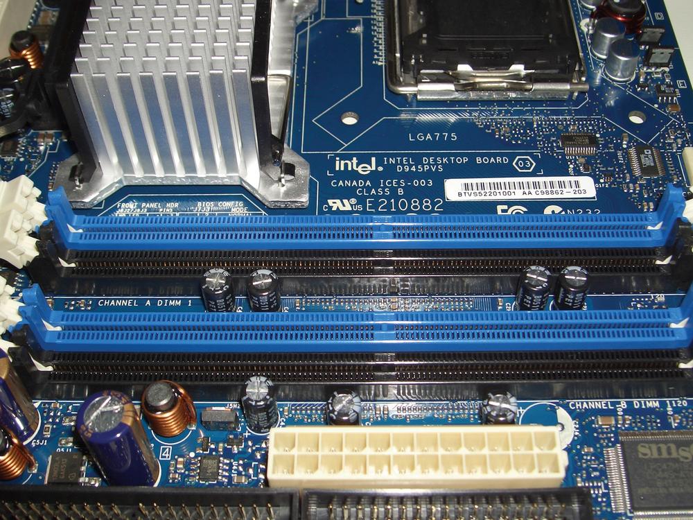
Intel's practice is to color-code DIMM 0 and place Channel A nearer the processor socket, so from top to bottom the slots in this motherboard are Channel A/DIMM 0, A/1, B/0, and B/1. Other motherboard manufacturers use different methods. If you were installing two memory modules in this motherboard, you'd install them in the blue slots, which would put one DIMM on Channel A and the other on Channel B. If instead you installed the two modules in the top two slots, you'd have the same amount of system memory available, but the motherboard would be forced to operate in single-channel memory mode, greatly slowing performance.
Standard memory, also called non-parity memory, uses 8 bits to store an 8-bit byte. ECC memory (Error Correcting Code memory), sometimes called parity memory, uses 9 bits to store an 8-bit byte. The extra bit provided by ECC memory is used to store error detection and correction information.
A non-parity memory module can neither detect nor correct errors. An ECC memory module can detect all multi-bit errors, correct all single-bit errors, and correct some multi-bit errors. Memory errors are so rare that most desktop systems use non-parity memory, which is less expensive and faster than ECC memory. In fact, most desktop chipsets do not support ECC memory. If you install ECC memory in such a system, it may not recognize the memory at all, but more likely it will simply treat the ECC memory as non-parity memory, ignoring the extra bit.
ECC memory is occasionally used in desktop systems, but is much more common in servers and other large, critical systems. Because ECC modules contain additional memory chips, in the ratio of 9:8, they typically cost 10% to 15% more than similar non-parity modules. Also, because the circuitry on ECC modules that calculates and stores ECC values imposes some overhead, ECC modules are marginally slower than similar non-parity modules.
We recommend using ECC memory modules only in the following situations:
If the currently installed memory modules are ECC, install identical or closely similar modules.
If you are installing a large amount of memory (2 GB or more), use ECC modules.
Otherwise, save your money and install non-parity modules.
Unbuffered memory modules allow the memory controller to interact directly with the memory chips on the module. Registered memory (also called buffered memory) modules place an additional layer of circuitry between the memory controller and the memory chips.
Registered memory is necessary in some environments, because all memory controllers have limitations on how many devices (individual memory chips) they can control, which in turn limits the maximum capacity of the memory modules they can use. When a memory controller interacts with an unbuffered memory module, it controls every memory chip directly. When a memory controller interacts with a registered memory module, it works only with the buffer circuitry; the actual memory chips are invisible to it.
The sole advantage of registered memory is that it permits a system to use higher-capacity memory modules. (The highest capacity modules at any given time are often available only in registered form.) The disadvantages of registered memory are that it is considerably more expensive than unbuffered memory and noticeably slower because of the additional overhead incurred from using a buffer.
Most desktop systems support only unbuffered memory modules. A few can use either registered or unbuffered memory modules. A very few desktop systems—notably, Socket 940 AMD models—require registered memory. If you are upgrading the memory in your system, we recommend that you use registered memory modules only in the following situations:
The system accepts only registered memory modules.
The system accepts unbuffered or registered memory modules, but registered modules are already installed.
The amount of memory you want to install requires using modules that are available only in registered form.
Motherboards differ in the specific memory configurations they support. It seems reasonable to assume that if a motherboard has unused memory slots, you should be able to upgrade the memory simply by installing any supported memory modules in those empty slots. Unfortunately, that's not always true. Several factors come into play, including the speed, capacity, density, and organization of the memory modules:
- Memory speed
Installing fast memory may reduce the number of DIMMs you can install. For example, a motherboard may have three DIMM slots, all of which can be populated with PC2700 DIMMs. But that motherboard may support at most two PC3200 DIMMs, forcing you to leave the third DIMM slot empty if you install PC3200 memory.
- Module capacity
Not all motherboards support all DIMM capacities. For example, some motherboards may support 256 MB DIMMs, but not 512 MB DIMMs. The allowable mix may also differ. For example, one motherboard may support 512 MB DIMMs in all four of its memory slots. Another may support 512 MB DIMMs in only two of its four slots, and require that you leave the other two slots vacant or install 256 MB or smaller DIMMs in those slots. Still another may support a maximum of 1 GB of RAM using 512 MB DIMMs, requiring you to leave two of its four memory slots vacant if you install 512 MB DIMMs in the first two slots.
- Row limits
Many motherboards limit the number of rows of memory that can be installed to some number smaller than the possible number of rows if all memory slots are populated. Single-sided DIMMs count as one row, and double-sided DIMMs as two rows. If a motherboard has four memory slots and limits installed memory to five rows, for example, that means you could install single-sided DIMMs in all four memory slots (for a total of four rows). Installing two double-sided DIMMs occupies four rows, leaving only one row available. You could install at most one more single-sided DIMM in that system, for a total of five rows.
- Memory density and organization
The memory chips used to build memory modules are made in different densities. Current modules use 256 megabit (Mb), 512 Mb, or 1 Gb chips. Older modules use 64 Mb or 128 Mb chips. Non-parity modules use 4, 8, or 16 chips, and ECC modules 5, 9, 10, or 18 chips. For example, a 512 MB non-parity memory module (8 bits per byte) could be made using four 1 Gb chips, eight 512 Mb chips, or sixteen 256 Mb chips. Similarly, a 512 MB ECC memory module (9 bits per byte) could be made using four 1 Gb chips and one 512 Mb chip, nine 512 Mb chips, eight 512 Mb chips and two 256 Mb chips, or eighteen 256 Mb chips.
The chipset memory controller used by an older motherboard may not recognize higher chip densities. For example, the memory controller in a particular motherboard may recognize chip densities of 64, 128, 256, and 512 Mb, but not 1 Gb. If you want to install a 512 MB memory module in that motherboard, you could use a module with eight 512 Mb chips (512X8) or sixteen 256 Mb chips (256X16), but not a module with four 1 Gb chips (1024X4).
Similarly, the memory controller used by a newer motherboard may not recognize low chip densities, which means that older, smaller capacity DIMMs may not work in it. For example, a recent motherboard may recognize only 256 Mb, 512 Mb, and 1 Gb memory chips. If you install an old 128 MB DIMM that uses eight 128 Mb chips in that motherboard, it will not be recognized.
Memory controllers also differ in the types of organization they support. Some controllers support X4, X8, and X16 modules, but many support only one or two of those organizations. For example, the Intel 945P chipset supports only X8 organization. If you install a 512X8 512 MB module (eight 512 Mb chips), the motherboard recognizes and uses the full 512 MB capacity. Other 512 MB organizations (1024X4 and 256X8) are not supported. The results of installing a module that uses an unsupported organization are unpredictable. The motherboard may recognize the module at some fraction of its nominal capacity, or it may simply not recognize the module.