Wireless networks use an access point (AP), also called a wireless access point (WAP), to provide a gateway to the wired network and a wireless local area network adapter (WLAN adapter or simply wireless adapter) to provide a link between a wireless client PC and the AP.
An AP connects to the wired network (or directly to a cable/DSL modem) and can simultaneously provide wireless links to many wireless adapters. A typical AP allows 32 or 64 wireless adapters to be connected simultaneously. All wireless adapters that connect to an AP share the wireless bandwidth provided by that AP. For example, if the AP provides 54 Mb/s of wireless bandwidth, all connected wireless adapters share that 54 Mb/s even though each adapter may have a maximum individual bandwidth of 54 Mb/s or more.
If only one wireless adapter is transferring data at a particular moment, that adapter gets the full available bandwidth. If several adapters are transferring data simultaneously, the available bandwidth is shared among them. Accordingly, the instantaneous bandwidth available to any particular adapter varies dynamically, depending on how many other adapters are also using bandwidth at that moment and how much bandwidth they are using.
A wireless network may have one or many APs. Although most home or SOHO networks get along fine with one AP, using a second AP provides additional area coverage, allows more wireless adapters to connect to the network simultaneously, and provides additional shared bandwidth. For example, one AP might have insufficient range to cover a large home, particularly one built with stone, steel studs, heavy plaster walls, or other materials that block radio waves. We can't imagine that the limit of 32 or 64 connected wireless adapters would be a problem in any home or SOHO environment, but the limited shared bandwidth might be.
Adding a second AP at some distance from the first AP extends the coverage area and doubles the bandwidth available to be shared among the wireless clients. Depending on their location, some wireless adapters may be within range of both APs, while others will be in range of only one or the other AP. If the wireless network is properly configured, client wireless adapters simply connect transparently to an available AP without user intervention. If the client is mobile—for example, a notebook computer being carried from room to room—the connection automatically hops from one AP to the next as the client moves within the coverage area.
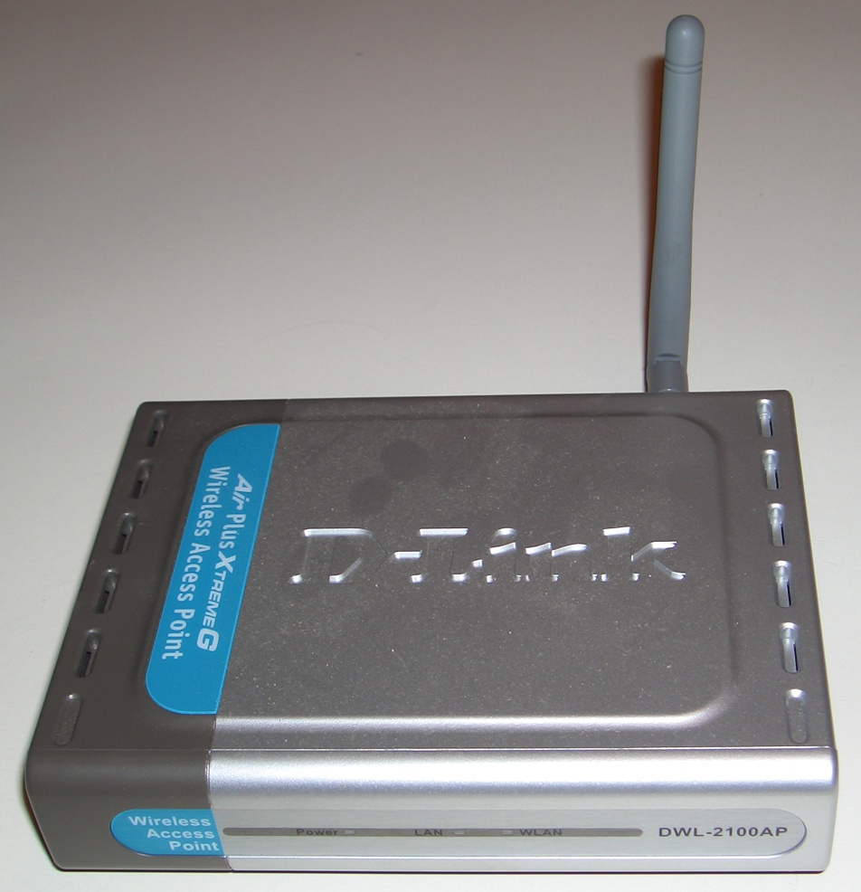
Figure 14-2 shows a typical AP intended for home or small-business use. This AP, a D-Link DWL-2100AP model, uses the ubiquitous low-gain, omnidirectional "rubber duck" antenna used by most wireless devices. The mounts used for these antennae allow the antennae to be oriented in all three dimensions to maximize signal strength and optimize coverage area. Some APs use permanently affixed antennae. Others, including this model, provide a socket for an external antenna. Various external antennae are available, including models suitable for outdoor mounting, models that provide higher gain than standard rubber duck antennae, and models that are highly directional.
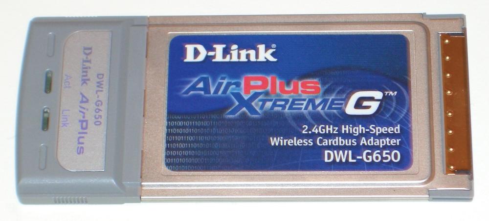
Clients connect to the wireless network using wireless adapters, which are functionally analogous to the standard Ethernet adapters used in a wired network. Wireless adapters are available in various interfaces, including PCI (for desktop systems), CardBus (for notebooks), PCMCIA (People Can't Memorize Computer Industry Acronyms) card adapters (for older notebooks and handheld devices), and USB (for any system). Like APs, PCI and USB wireless adapters are normally supplied with a low-gain, omnidirectional rubber-duck antenna that can usually be replaced with an external high-gain or unidirectional antenna. Figure 14-3 shows a D-Link AirPlus ExtremeG DWL-G520, which is a typical PCI wireless adapter. CardBus wireless adapters, like the D-Link DWL-G650 shown in Figure 14-4, have an internal, low-gain, omnidirectional antenna, and make no provision for using an external antenna. However, certain models of CardBus (or PCMCIA) adapters, such as some Proxim Orinoco cards, include an external antenna port.

The range of a wireless connection depends on many factors, including its speed, amount of interference, obstructions in the signal path, and the types of antennae used. All other things being equal, though, the range of a connection is determined by how powerful the transmitter is and how sensitive the receiver. Different brands and models of wireless components may differ significantly in both respects.
The transmitter power of wireless networking components is usually stated in dBm, and may range from 0 dBm (defined as 1 milliwatt or mW) to 30 dBm (just over 1,000 mW). An increase or decrease of about 3 dBm corresponds to a doubling or halving of transmission power. For example, an output of 3 dBm corresponds to about 2 mW. An increase or decrease of 10 dBm corresponds to increasing or decreasing transmitter power by a factor of 10. For example, an output of 10 dBm is about 10 mW; 20 dBm about 100 mW; and 30 dBm about 1,000 mW. All other things being equal, increasing power output increases range and transmission speed.
Wireless devices may use fixed transmission power, set transmission power dynamically under firmware control, or allow transmission power to be set manually. The amount of transmission power needed varies with the distance between devices, the sensitivity of the receiver, the data rate of the link, the amount of obstruction in the signal path, and other factors. In general, longer distances between devices and higher data rates require more transmission power.
You might think the best idea would be for all devices to use maximum transmission power all the time, but high power is not always desirable. Using more power than needed does not improve the speed or quality of the wireless link; it simply introduces unnecessary RF into the environment, where it may interfere with other wireless devices that would otherwise be able to use the same channel without conflicts.
Accordingly, the firmware of some wireless devices is programmed to negotiate link characteristics with other wireless devices, including transmitter power, to establish an optimum connection at the minimum required power level. This negotiation can be done at very low data rates, so the initial contact between the devices can occur at low power. Each device tells the other about its own capabilities, including the fastest link speed it supports. The devices then increase their transmitter power to the minimum level needed to support the highest common data rate. If the maximum available transmitter power is insufficient to support their highest common data rate, they fall back to a lower data rate, using whatever power level is needed to support that lower data rate.
Other wireless devices allow transmission power to be set manually, usually within a range of a few mW up to perhaps 100 or 200 mW. Often, the output power is not stated numerically, but instead is named (Full, Half, Quarter, Eighth, and so on) or as a maximum output power with options to reduce output by a series of 3 dB steps, each of which halves output power. Still other wireless devices make no provision for adjusting transmission power, instead using a fixed transmission power, usually 30 mW or so.
The flip side of transmitter power is receiver sensitivity. All other things being equal, a more sensitive receiver can sustain a connection with a weaker signal than a receiver with lower sensitivity. A sensitive receiver is as important as a powerful transmitter, because signal strength drops rapidly with increasing distance from the transmitter and because higher data rates require stronger signals.
If you are building a wireless network for which range is critical, particularly if your signal paths are obstructed, it's worth paying attention to the receiver sensitivity of components you are considering using. For example, the D-Link DWL-2100AP has excellent receiver sensitivity. A cheap, no-name component might have actual receiver sensitivity 10 dBm lower than the D-Link model (the documentation for the cheesy AP probably won't admit that, but we're talking real-world here). That means when the D-Link AP is at its maximum range to sustain a 54 Mb/s link, the cheap AP might sustain only a 24 or 36 Mb/s link. Worse still, if the D-Link AP is at its maximum range to support a 36 Mb/s link, the cheap AP might sustain only a 6 or 9 Mb/s link.
Most mainstream wireless components are supplied with a standard "rubber duck" antenna, which is usually described as omnidirectional. That's true in a sense, but the standard antenna radiates omnidirectionally primarily in one plane. For example, with the antenna oriented vertically (at 90°, relative to the horizontal plane), as shown in Figure 14-5, the radiation pattern resembles a doughnut extending horizontally outward in all directions. If this AP were installed on one floor of a home, for example, its coverage area might include all rooms on that same floor, but rooms on floors above and below its location would receive a weak signal.

Because antenna orientation has a major effect on coverage area, most antenna mounts permit the antenna to be rotated in all dimensions. For example, Figure 14-6 shows the antenna in the same vertical plane as the preceding image, but oriented at 45°, relative to the horizontal plane. With the antenna oriented this way, the AP provides a smaller coverage area on the floor where it is located, with added coverage on that portion of the floor above located to the right of the AP and added coverage on that portion of the floor below located to the left of the AP.
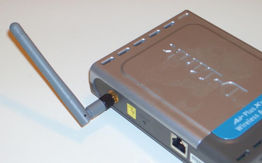
Figure 14-6. Antenna tilted to provide additional vertical coverage at the expense of horizontal coverage
Similarly, Figure 14-7 shows the antenna tilted at 45° in both the horizontal and vertical planes relative to the first image. With the antenna oriented this way, the AP provides some horizontal coverage on the floor where it is located, with added coverage on that portion of the floor above located to the right front of the AP and added coverage on that portion of the floor below located to the left rear of the AP.
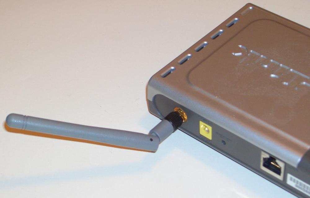
Figure 14-7. Antenna tilted to provide additional front-to-rear vertical coverage at the expense of horizontal and vertical right-to-left coverage
AP antenna orientation has a major impact on coverage area. Changing antenna orientation by even a few degrees can make major differences in signal strength throughout the coverage area, benefiting some areas at the expense of others. Also, obstructions are not necessarily equally obstructive at different antenna orientations. When you install a wireless network, don't simply orient the AP antenna vertically and hope for the best. Spend some time playing around with antenna orientation to see how it affects signal strength throughout your coverage area. Use a notebook with a wireless adapter and run the site-survey software provided with the wireless adapter, or a package such as Network Stumbler (http://www.stumbler.net), to optimize the coverage area.