Chapter 12
Electric Circuits
GOALS
By the end of this chapter, you will be able to:
• Explain the basics of circuits, including the variables current, resistance, and voltage
• Explain Kirchhoff’s circuit rules
• Apply Kirchhoff’s circuit rules to circuits with resistors in them
• Apply Kirchhoff’s circuit rules to circuits with capacitors in them
• Apply Kirchhoff’s circuits rules to circuits with both resistors and capacitors in them
Lesson 12.1
Circuit Basics
Consider the case of a capacitor in a vacuum. There is no way to get any of the charges from one plate to the other without the use of a conducting wire, because the conducting electrons are still strongly attracted to the plate. If one were to run a conducting wire from one plate to another, you could allow charges to move from one plate to another. This movement of charges is known as a current, i, and is defined as
Equation 12.1
i = 
The unit of current is known as the Ampere, or the amp, A. This unit is named after the French physicist Andre-Marie Ampere. Ampere was an important figure in the study of magnetism, which we will discuss later.
There is a property inherent to all conductors known as resistance. Resistance is internal friction within a conducting material. This is due to the fact that a conductor is made out of actual atoms or molecules. As charged particles move through, they collide with these atoms or molecules in the material, which slows down the movement of charges across the conductor, as well as causes the charged particles to dissipate energy. As you know, in order for a charge to lose electric potential energy, it has to undergo a change in electric potential. The change in electric potential across a material of resistance R is given by Ohm’s Law:
Equation 12.2
Δϕ = iR
where i is just the current through the material. The SI unit of resistance is the Ohm, Ω, named after the German physicist Georg Ohm. The resistance of any conductive material of constant cross section (a cylinder or rectangular prism, for instance) is given by
Equation 12.3
R = ρ
where L is the length of the conductor, A is the cross sectional area, and ρ is the resistivity, which is the inherent resistance of a material. The units of resistivity are Ω·m.
Because there is a change in potential across a conductor, due to the resistance, there has to be an electric field within the conductor. This is different from the last chapter when we discussed the fact that conductors do not have electric fields in them. That applied to the case of electrostatics, when none of the charges were moving. Now that there is a current within the conductor, there has to be an electric field due to this change in potential.

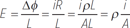
The electric field within a conductor of length L and resistivity ρ, which has a potential difference across it of Δϕ, is
E = 
Notice that we have dropped the negative sign. This is because we are just interested in the magnitude of the electric field, and not its direction. Using Ohm’s Law, we have
We want to define a new quantity known as the current density, J, which is the current divided by the cross sectional area of a conductor. Then, the electric field, in general, is
![]() = ρ
= ρ![]()
Since we are talking about vectors here, the sign is important. Since we have attributed a direction to the current, it is important to know that current always points in the flow of positive charges in a circuit. Positive charges move from a high potential to a low potential, so the current will point in the same direction as the electric field. In the case of a parallel plate capacitor with a conducting wire between the plates, the current will point from the positive plate to the negative plate. But it is important to know that positive charges do not actually move in a circuit. Electrons are the particles that are free to move in conducting materials, so they move opposite to the direction of current. The reason why this convention arose is because the dynamics governing circuits was mostly worked out in the mid 1800s, whereas the electron wasn’t discovered until the late 1800s. Our current model of the atom, known as the Rutherford model, wasn’t introduced until 1911. This describes an atom as having a small, dense, positive nucleus with a cloud of electrons around it.
EXAMPLE 
What is the current through a conducting wire of resistance R placed between the plates of a capacitor, C, charged to Q. Consider the charge Q very large, so that it does not drop considerably as the current runs through the conducting wire.
In this case, the potential difference across the conducting wire is the potential difference across the capacitor, as given by Equation 11.19:
Δϕ = 
so, using Ohm’s Law (Equation 12.2), the current through the wire is
i = 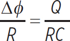
Notice that, since current is defined as a charge over time, RC has to be some time value. This will become important at the end of the chapter.

The above example is the simplest example of an electrical circuit, typically referred to simply as a circuit. A circuit is formed when a charge source is connected to a charge sink by a conducting wire. In circuits, we consider the conducting wire to have no resistance, and therefore no change in potential across it. Typically, a battery acts as both a source and a sink of charges. A battery is like a capacitor with an infinite charge, so it always produces a constant potential difference.
Now that we are switching over to discussing circuits, we will use a slightly different nomenclature. Instead of using the term “potential difference,” which is just the change in electric potential between two points, we will use the term voltage, V. Note that, since they are the same,
V = Δϕ
This is just a matter of semantics, but it is important to know the term voltage, as most people use it to describe the potential difference between two points in a circuit.
EXAMPLE 
Consider the following resistor placed along a conducting wire.
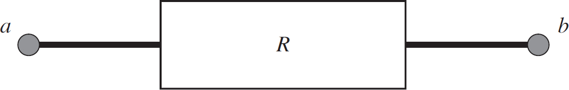
In this case, ϕa = 10 V, ϕb = 1 V, and R = 10 Ω. What is the value of the current? In which direction does it flow?
Unless otherwise stated, we will not assume any resistance in conducting wires. This means that a charge will not lose any energy moving from a to the edge of the resistor, or from the opposite edge of the resistor to b. This means that the potential does not change along the wire, and so the side of the resistor near a is at the same potential as a, and the side of the resistor near b is at the same potential as b. So, according to Ohm’s Law,
i =  = 0.9 A
Which way does this current point? Well, positive charges move from a high potential to a low potential, so the current flows from a to b. Note, however, that the electrons are actually moving from b to a, because negative charges move from a low potential to a high potential.

Since the voltage across a conductor of resistance R is V = iR, the change in potential energy of a charge q moving through that conductor is
ΔU = qV = qiR
If the charge undergoes this change in potential energy in a time Δt, then the resistor is reducing the charge’s energy at the following rate:
P = 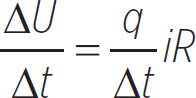 = i2R
= i2R
This is known as Joule’s Law. Using Ohm’s Law, we can also represent it as
P = i2R = iV = 
Lesson 12.2
Kirchhoff’s Circuit Rules
Circuits are typically diagrammed, so it is important to know the common symbols appearing in a circuit diagram. The symbols for a battery, a resistor, and a capacitor are given in the following figure.
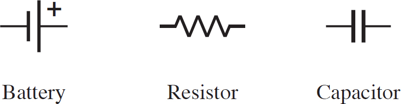
Figure 12.1: Common Circuit Symbols
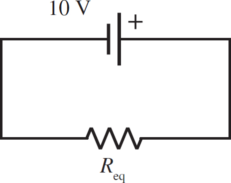
A simple circuit with a single battery at voltage V and a resistor of resistance R is illustrated in the following figure.

Figure 12.2: Single Resistor Circuit
When an electron leaves the negative terminal of a battery, it moves along the circuit, through the resistor, and back into the battery. Because this electron begins and ends in the same location, its net change in potential energy is zero:
Equation 12.4
Δϕloop = 0
This is known as Kirchhoff’s Loop Rule, named after the German physicist Gustav Kirchhoff. This means that, in the previous circuit, the voltage gained by an electron from the battery is lost by the resistor in the circuit. This means that the voltage across the resistor is simply
VR = V
and so the current through the resistor is
i = 
A few things about this result. First, notice that in order to apply Ohm’s Law, you need to know the voltage across the resistor. According to Kirchoff’s Loop Rule, you know that the voltage across the resistor is equal to the voltage across the battery, so you can find the current through the resistor. Now, current can be changed only by a junction in the circuit: a point where branches of a circuit meet, new branches of a circuit emanate, or both. In the following figure, there is a junction formed by one branch of a circuit becoming two branches.

Figure 12.3: Circuit Junction
In Figure 12.2, which has a single battery and a single resistor, there are no junctions, so the current cannot change in the circuit. Therefore, V/R is the current produced by the battery, and it is the current at every point in the circuit. In general, current is conserved at a junction point, meaning the amount of current going into a junction has to equal the amount of current leaving the junction:
Equation 12.5
∑iin =∑iout
This is known as Kirchhoff’s Junction Rule. This combined with the loop rule are known as Kirchhoff’s circuit rules.
EXAMPLE 
What is the current through each resistor and the current produced by the battery in the following circuit?
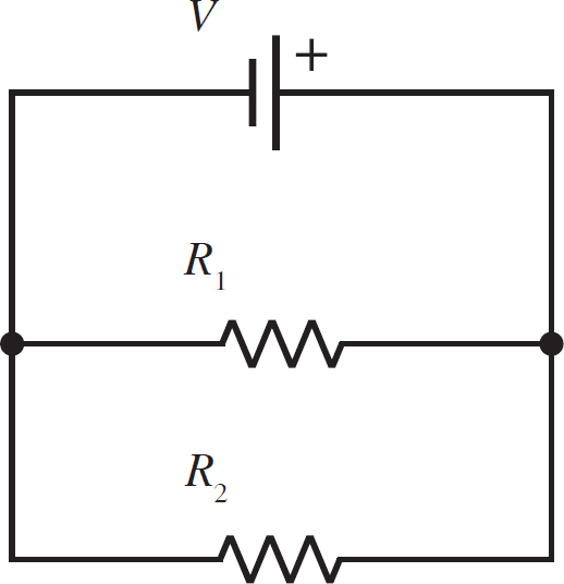
There are three loops in this circuit, the upper loop with V and R1, the lower loop with R1 and R2, and the outer loop with V and R2. In each of these three loops, the total voltage has to be zero. Focusing on the upper loop, you can see that this means the voltage across R1 must be the voltage of the battery, V. You can also see that, according to the outer loop, the voltage across R2 must be the voltage of the battery, V, as well. You can see that this then satisfies the loop rule for the lower loop.
So, using Ohm’s Law, the current across R1 has to be
i1 = 
and the current across R2 is
i2 = 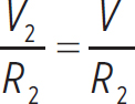
Now, what direction do these currents flow through the resistors? Well, notice that the battery is going to produce a current out of its positive terminal, which we will call i. i will flow to the right in its branch and then down, hitting the junction that separates the two resistors. i will split, and the two resulting currents, which we will call i1 and i2, will begin moving leftwards across their respective resistors. This is illustrated in the following figure.

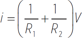
So, lastly, what is the current produced by the battery? Well, as mentioned, the current produced by the battery, i, goes into the junction on the right side of the circuit and the two currents, i1 and i2, leave the junction. You can use the junction rule to find i:
i = i1 + i2 = 
Take note of this result, because it will be important in the next section.

EXAMPLE 
What is the ratio of the current in each branch of the following loop?

You know that in this loop the voltage has to be zero. So, the voltage across resistor R1 has to equal the voltage across the resistor, R2. If we call the current through R1 to be i1, and the current through R2 to be i2, then Kirchhoff’s Loop Rule states
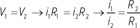
Let’s look at this result for a moment. If R1 > R2, then i1 < i2. If R2 > R1, then i2 < i1. What this tells us is that the larger current will go along the path that has a lower resistance. Try this out for yourself by choosing a value for R1 and R2, where R1 is bigger, and see which is the larger current. Then choose a value for R1 and R2 where R2 is bigger, and see which is the larger current. In general, current tries to take the path of least resistance, which you may have heard before. This is a direct consequence of Kirchhoff’s Loop Rule.

Now let’s discuss how to actually measure the currents and voltages in a circuit using instruments known as ammeters and voltmeters, respectively. Consider the following circuits:

Figure 12.4: Voltage and Current Measurement
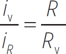
The circuit on the left is set up to measure the voltage across the resistor R, and the circuit on the right is set up to measure the current through resistor R. But how is this accomplished? Well, in each case the measuring device is made of conductive wire, so it has some resistance. In the case of the voltmeter, we know from the previous example that some current is going to go through the resistor R and some current is going to go through the voltmeter (let’s say it has a resistance RV). What is the ratio of these currents? This is just the result of our last example:
Both the resistor and the voltmeter are going to be at the same voltage—this is just the loop rule. Now, what is the voltage across the resistor? Ohm’s Law says it should be
VR = iRR
If we were not going to measure the voltage at all, then the resistor would have whatever current was produced by the battery, i. By adding a voltmeter, now the current has to split between the resistor and the voltmeter. Since the voltmeter gets some of this current, this means that the current through the resistor is smaller than it should be. We don’t want our measurements to affect the circuit at all, so how do we get around this? Well, the amount of current that the voltmeter receives depends on its resistance, right? So if the resistance is very, very large, the current it receives is very, very little. Ideally, you would want the resistance of a voltmeter to be ∞; that way, no current would go through it and thus would not disturb the circuit.
So, the ideal way to measure the voltage across a resistor is to connect a voltmeter with infinite resistance across it, as depicted in Figure 12.4. But what about measuring the current? For this, refer to the circuit on the right. In this case, we placed the ammeter in the same branch as the resistor. Let’s say that the ammeter, which is also made of conducting wires like the voltmeter, has a resistance RA. What current does it measure?
Well, since it lies on the same branch as the resistor, it has to have the same current as the resistor (which is good, because that is the current we want to measure). In this case, the voltage across the ammeter is
VA = iRA
We already know that the voltage across the resistor will be VR = iR. So, the total voltage across the wire that holds the ammeter is
Vwire = iRA + iR = i(RA + R)
According to the loop rule, this has to equal the voltage of the battery, V, so the current measured by the ammeter would be
V = Vwire = i(RA + R) → i = 
Notice that the larger the resistance the ammeter has, the lower the current in the circuit. The ammeter itself affects the circuit and reduces the current in the circuit. In order to have no affect on the circuit, or the current in the circuit, we would want to use an ammeter with a very, very small resistance. Ideally, we would want the resistance to be 0. So, the ideal way to measure the current through a resistor is by connecting an ammeter with zero resistance in the manner Figure 12.4 depicts.
Lesson 12.3
Circuits with Multiple Resistors
So far we’ve dealt thoroughly with circuits with a single resistor in them, and even brushed upon circuits with two resistors. Now we want to deal with circuits that have more than two resistors. These circuits could have as many resistors as we please. The process for solving for the pertinent variables in these circuits doesn’t change with the number of resistors. First, let’s look back to Example 3. We had the following circuit:

Figure 12.5: Circuit with Two Resistors in Parallel
These resistors are said to be in a parallel connection because they are on parallel wires. More technically, any two resistors that are on opposite branches in a loop are in a parallel connection, and they have the same voltage. We found in this case that the current produced by the battery is
The above result looks an awful lot like Ohm’s Law, if the battery were connected to a single resistor, Req, equal to

In this case, the current would be
i = 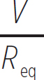
which is exactly what we would get if the battery V were connected to a single resistor Req. This result illustrates a concept known as equivalent resistance. No matter the arrangement of resistors in a circuit, the battery will still produce a current as if it were connected to an imaginary combination of the individual resistors within the circuit. Consider the following circuit with n resistors connected in parallel. In this circuit, all of the currents have already been labeled, but we have to go through and solve for each of them using the loop and junction rules.

Figure 12.6: Circuit with n Resistors in Parallel
Recall that each branch should have the same voltage as the battery, so each of the n resistors has a voltage V. This means that each of the n resistors has the current
ij = 
where j is an arbitrary choice of resistor. For instance, resistor 2 has a current i2 = V/R2. Now, let’s start finding the other currents given in the figure. The current produced by the battery is
i = i1 + i 
But what is i ? This is
i = i2 + i 
So, the current produced by the battery is
i = i1 + i2 + i
Notice now that i isn’t solved for. This is
i = i2 + i 
And so on and so on, until we finally have
i = i1 + i2 +…+ in
We showed previously that the current through any resistor Rj is just V/Rj, so
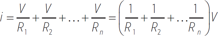
Once again, this looks just like a single resistor connected to a battery with an equivalent resistance of
Equation 12.6
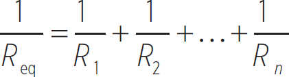
So, the equivalent resistance of any number of resistors in parallel is given by the above equation. How does this help us solve problems? Let’s do an example.
EXAMPLE 
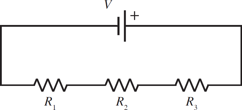
What is the current through each resistor in the following circuit, as well as the current produced by the battery, given that V = 9 V, R1 = 1 Ω, R2 = 5 Ω, and R3 = 2 Ω.
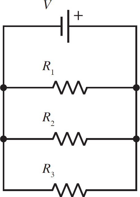
While there are other, possibly faster ways of solving this problem using concepts we have already covered, we want to solve this specifically using the concept of equivalent resistance. For your own practice, it would be a good idea to solve this problem using the loop and junction rules. Using Equation 12.6, the equivalent resistance of these three resistors in parallel is

So, the equivalent resistance is the inverse of this,
Req = 0.59 Ω
This means that the current produced by the battery is
i = 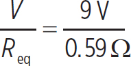 = 15.3 A
Using the concept of equivalent resistance, we can redraw our circuit:

Now we have to work backward, reproducing the resistors that we used to form our equivalent resistors. Since these resistors were all in parallel, we know that their voltages all have to be the same as the voltage of the equivalent resistor, or 9 V. This means

And, now, we can find each of the individual currents. These are
i1 = 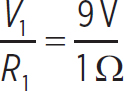 = 9 A
= 9 A
i2 =  = 1.8 A
i3 =  = 4.5 A
Note that these currents sum to 15.3 A, which is the current produced by the battery, as we know they should.

Parallel connections are not the only type of connections that resistors can be arranged in. They can also be arranged in series connections, where all of the resistors lie on the same branch (as opposed to parallel connections, where resistors lie on parallel branches). Consider the following circuit with n resistors in series, as shown in the following figure.

Figure 12.7: Circuit with n Resistors in Series
Each resistor has the same current because they all lie on the same branch. So, each resistor has a voltage across it of
Vj = iRj
where j is any random resistor. For instance, for resistor 2, V2 = iR2. This means that the total voltage across the branch carrying all of the resistors is
Vbranch = V1 + V2 +…+ Vn = iR1 + iR2 +…+ iRn = i(R1 + R2 +…Rn)
According to the loop rule, the branch carrying the resistors has to have the same voltage as the branch carrying the battery. So, the above voltage just equals the voltage of the battery:
V = i(R1 + R2 +…Rn)
Notice that this is exactly the result you would get if the battery were connected to a single equivalent resistor of resistance
Equation 12.7
Req = R1 + R2 +…+ Rn
So any number of resistors in series combined to form a single, equivalent resistor with the resistance given by the above equation. Let’s see how this helps us solve a problem.
EXAMPLE 
What is the current produced by the battery, as well as the voltage across each resistor, in the following circuit? In this circuit, V = 5 V, R1 = 4 Ω, R2 = 3 Ω, and R3 = 7 Ω.
First, find the equivalent resistance of the circuit. Since the resistors are in series, this is simply the sum of the individual resistances:
Req = R1 + R2 + R3 = 4 Ω + 3 Ω + 7 Ω = 14 Ω
Using the equivalent resistance, the circuit now looks like
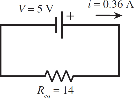
This means that the current in the circuit is
i = 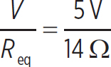 = 0.36 A
Now you want to expand our circuit back to its original configuration. Since the equivalent resistor was formed by three resistors in series, each of the individual resistors carries the same current as the equivalent resistor, 0.36 A. This is illustrated in the following figure.
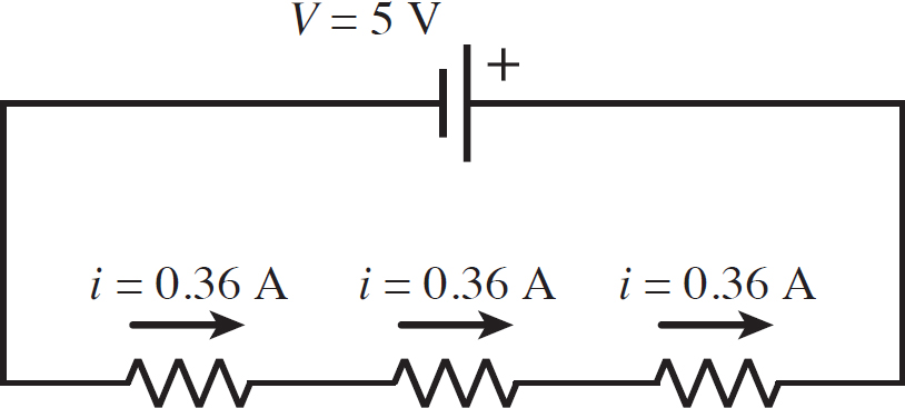
So, the voltages across each resistor can be found with Ohm’s Law:
V1 = iR1 = (0.36 A)(4 Ω) = 1.4 V
V2 = iR2 = (0.36 A)(3 Ω) = 1.1 V
V3 = iR3 = (0.36 A)(7 Ω) = 2.5 V
And the individual voltages of each resistor sum to 5 V, the resistor of the battery, as required by the loop rule.

While we learned enough about the loop and junction rule to simply figure the previous two examples out without exploiting equivalent resistance, our knowledge of equivalent resistance will come in handy when dealing with a mixture of series and parallel connections, as in the next example.
EXAMPLE 
What are the currents and voltages of each resistor in the following circuit, as well as the current produced by the battery?
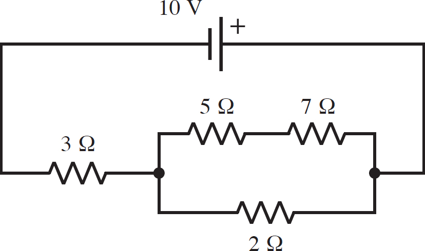
You want to find the equivalent resistance of this circuit. You should always start with any loops in the circuit. In this case, you cannot say that either the 5 Ω resistor or the 7 Ω resistor are in parallel with the 2 Ω resistor, because they have different voltages. However, the 5 Ω and the 7 Ω resistors are in series, so begin there. Call this resistance Req,1. This means that the circuit will look like
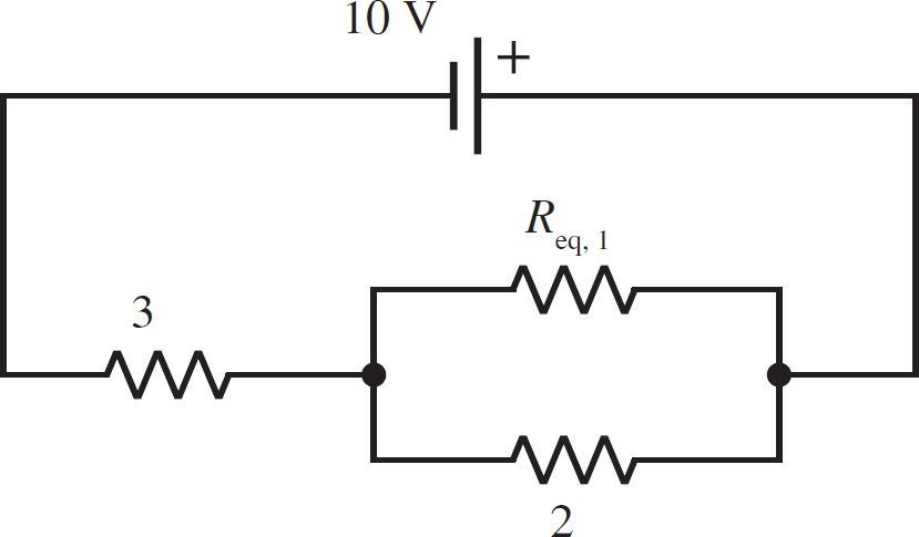
with
Req,1 = 5 Ω + 7 Ω = 12 Ω
Now you can deal with the loop, since it is two resistors in parallel. If you call this equivalent resistance Req,2, then your circuit will look like

with
Req, 2 = 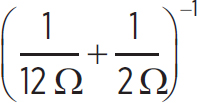 −1 = 1.7 Ω
So, you are left with two resistors in series. Thus, the final circuit will look like
with Req being the sum of the two resistors in series:
Req = 3 Ω + 1.7 Ω = 4.7 Ω
We can now find the current produced by the battery:
i =  = 2.1 A
Now work backwards to find the currents and voltages of the resistors that make up our circuit. First, the equivalent resistor was produced by two resistors in series, the 3 Ω resistor and Req,2. Each of these carries the same current as Req, 2.1 A, so the only things you can solve for are the voltages. The voltage across the 3 Ω resistor is
V3 Ω = (2.1 A)(3 Ω) = 6.3 V
The voltage across Req,2 is
Veq,2 = (2.1 A)(1.7 Ω) = 3.6 V
Since Req,2 was formed by two resistors in parallel, you know that each of these resistors has the same voltage as Req,2, 3.6 V. So, the current through the 2 Ω resistor is
i2Ω =  = 1.8 A
and the current through Req,1 is
ieq, 1 =  = 0.3 A
Finally, expand Req,1 back into the 5 Ω and 7 Ω resistors it was made of. Since these were in series, they both carry the same current as Req,1, 0.3 A. So, their voltages are
V5 Ω = (0.3 A)(5 Ω) = 1.5 V
V7 Ω = (0.3 A)(7 Ω) = 2.1 V
To recap, here are all the values asked for by the problem:
i = 2.1 A
i3 Ω = 2.1 A
i5 Ω = 0.3 A
i7 Ω = 0.3 A
i2 Ω = 1.8 A
V3 Ω = 6.3 V
V5 Ω = 1.5 V
V7 Ω = 2.1V
V2 Ω = 3.6V

Lesson 12.4
Capacitor Circuits
A circuit can also be composed solely of capacitors. Let’s look at a simple example: a battery connected to a single capacitor. This is illustrated in the following figure.

Figure 12.8: Single Capacitor Circuit
What happens in this circuit if the capacitor is initially uncharged? Well, electrons start to leave the negative terminal of the battery, moving toward the neutral terminal of the capacitor that is near. This is an increase in potential for the electrons, which is why they move. In addition, electrons leave the other negative terminal of the capacitor and move toward the positive terminal of the battery. This is also an increase in potential for the electrons. As this is occurring, don’t forget that the current goes in the opposite direction. This is illustrated in the next figure.
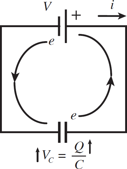
Figure 12.9: Single Capacitor Circuit Explained
Notice, though, that as the capacitor gains charge, the voltage across it increases. How high will the voltage go? It will increase until it matches the voltage produced by the battery. This is just the loop rule. So, what happens then? Well, at this point, the negative terminal of the battery is at the same potential as the negative terminal of the capacitor, and the positive terminal of the battery is at the same potential as the positive terminal of the capacitor. This means that electrons will no longer flow through the wire because there is no change in potential to motivate them. So the current stops when the capacitor’s voltage matches the voltage of the battery.
The amount of time it takes to charge the capacitor turns out to be extremely small, so the charging process can be ignored for now. What we are more interested in are the equilibrium conditions of capacitor circuits, when the voltage of the capacitor matches the voltage of the battery and current no longer flows. In this case, what is the charge on the capacitor?
Well, by the loop rule, you know that the voltage across the capacitor has to be V, the voltage produced by the battery. The equation relating the voltage across a capacitor and its charge is given by Equation 11.19. This yields a charge of
Q = CV
When discussing resistor circuits, we were interested in the voltages across the resistors and the resulting current produced within them. Now for capacitor circuits, which do not have a current running through them, we will be interested in the voltages across the capacitors and the resulting charges they must carry. It is straightforward to solve this for a single capacitor, but what about a circuit with multiple capacitors?
Just like with resistors, there are series and parallel connections between capacitors. Let’s start with parallel connections. In the following figure, n capacitors are connected in parallel.

Figure 12.10: Circuit with n Capacitors in Parallel
The voltage on each of these capacitors is equal to that of the battery, as per the loop rule. This means that the total charge of all the capacitors combined is
Q = Q1 + Q2 +…+ Qn = C1V + C2V +…+ CnV = (C1 + C2 +…+ Cn)V
This is exactly the charge you would expect to find on a single capacitor connected to the battery of equivalent capacitance:
Equation 12.8
Ceq = C1 + C2 +…+ Cn
So, the equivalent capacitance for n capacitors in parallel is the sum of the capacitances. Note that this is in contrast to resistors. The equivalent resistance of n resistors in parallel is found using the sum of the inverses of the resistances. Next, let’s consider n capacitors in series, as shown in Figure 12.11.

Figure 12.11 Circuit with n Capacitors in Series
It turns out that in series all capacitors have the same charge. This is because in order for one plate of a capacitor to acquire a charge +Q, the plate of the capacitor near it has to lose that charge, acquiring a charge −Q. This is shown in the following figure.

Figure 12.12: Flow of Charge Between Capacitors in Series
This is analogous to how resistors in series have the same current. So, the voltage on the wire carrying the n capacitors in series would be
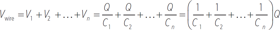
Notice that this looks like an equivalent capacitor connected to the battery of capacitance
Equation 12.9
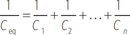
As you might have expected, this is also the opposite of the analogous equation for resistors. In a series, the equivalent resistance is the sum of the individual resistances.
We will apply the concept of equivalent capacitance in the exact same manner as we did for equivalent resistance to solve problems with complex arrangements of capacitors. Let’s do an example to illustrate this concept.
EXAMPLE 
Find the charge and voltage of each of the capacitors in the following circuit.
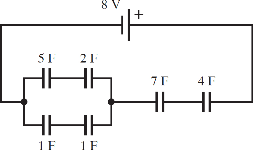
You can see three clear pairs of capacitors in series. These three all need to be combined, resulting in the following circuit:
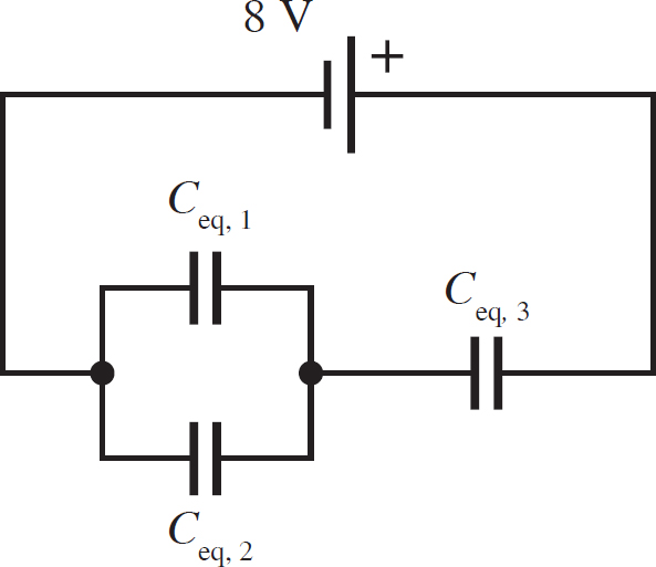
with the following equivalent capacitances:
Ceq, 1 = 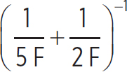 = 1.43 F
Ceq, 2 =  = 0.5 F
Ceq, 3 =  = 2.55 F
This leaves you with one loop that you have to close. The resulting circuit is shown in the following figure.
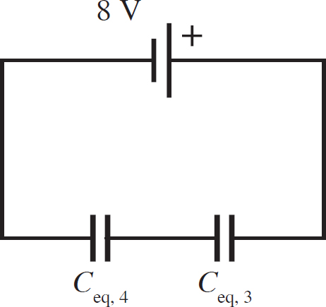
Since Ceq,1 and Ceq,2 were in parallel, Ceq,4 is just the sum of their capacitances:
Ceq,4 = 1.43 F + 0.5 F = 1.93 F
So, you are left with two capacitors in series, Ceq,4 and Ceq,3. The resulting equivalent capacitance of the circuit is therefore
Ceq =  = 1.1 F
So, the charge on the equivalent capacitor is
Qeq = (1.1 F)(8 V) = 8.8 C
Now you have to go through the process of breaking up this equivalent capacitor. Since it was formed by two capacitors in series, Ceq,4 and Ceq,3, these capacitors have the same charge as the equivalent capacitor, 8.8 C. So their voltages are
veq,4 =  = 4.56V
veq,3 =  = 3.45V
Notice that 4.56 V + 3.45 V = 8.01 V (rounding), as the loop rule requires. Now you need to break up each of these equivalent capacitors. Start with Ceq,4. This breaks into two capacitors that were in parallel, Ceq,1 and Ceq,2, so they both have the same voltage as Ceq,4, 4.56 V. Their respective charges will then be
Qeq,1 = (1.43 F)(4.56 V) = 6.52 C
Qeq,2 = (0.5 F)(4.56 V) = 2.28 C
Since both of these equivalent capacitors are made up of pairs of capacitors in series, the charge on the 5 F and the 2 F capacitors is just 6.52 C, the charge on Ceq,1, and the charge on the two 1 F capacitors is just 2.28 C, the charge on Ceq,2. So, the four voltages are
V5F =  = 1.30 V
V2F =  = 3.26 V
V1F =  = 2.28 V
We only included the voltage across the 1 F capacitor once, even though there are two 1 F capacitors; they both have the same voltage, 2.28 V. Note that the loop rule is satisfied for this loop as well. The voltage of the 5 F and 2 F capacitors is 1.30 V + 3.26 V = 4.56 V, and the voltage of the two 1 F capacitors is 2.28 V + 2.28 V = 4.56 V.
Now that you know everything for the 5 F, 2 F, and both 1 F capacitors, you still need to deal with Ceq,3. This was formed by two capacitors in series, so the 7 F and the 4 F capacitors both have the same charge as Ceq,3, 8.8 C. So, their voltages are
V7F =  = 1.2 6V
V4F =  = 2.2 V
Note that the voltage of the loop (given by the voltage across Ceq,4) is 4.56 V, meaning the loop rule is satisfied because 4.56 V + 1.26 V + 2.2 V = 8.02 V (rounding), the voltage of the battery. For clarity, all of the values that were asked for are listed:
Q5 F = 6.52 C
Q2 F = 6.52 C
Q1 F = 2.28 C
Q7 F = 8.8 C
Q4 F = 8.8 C
V5 F = 1.30 V
V2 F = 3.26 V
V1 F = 2.28 V
V7 F = 1.26 V
V4 F = 2.2 V

Lesson 12.5
RC Circuits
An RC circuit is a circuit with both resistors and capacitors. An example of an RC circuit is given in the following figure.

Figure 12.13: A Simple RC Circuit
What happens to the charges in this circuit? Well, exactly what happened to the charges in the capacitor circuits. Charges move from the battery to the capacitor until the voltage of the capacitor equals the voltage of the battery; then the current stops. However, adding in a resistor slows this process down to the point at which it can be measured.
So, what does the current look like during the charging? Well, let’s analyze the variables in the circuit as the charge moves. This is illustrated in the following figure.

Figure 12.14: A Simple RC Circuit Explained
As charge builds on the capacitor, the voltage of the capacitor increases. At all times, the voltage of the resistor plus the voltage of the capacitor must equal the voltage of the battery. Therefore, as the voltage of the capacitor increases, the voltage of the resistor must decrease. As the voltage of the resistor decreases, the current through the resistor must decrease, as per Ohm’s Law. Since this circuit is made out of one piece of wire, this means that the current produced by the battery must also decrease, since it has to be the same as the current through the resistor.
So, the current initially starts out large, it drops as the charge builds on the capacitor until the voltage across the capacitor is the same as the voltage produced by the battery, and then stops. It is clear that, initially, the current should just be
i0 = 
because the capacitor has no charge and therefore the voltage of the resistor is equal to the voltage of the battery. At any time during the charging process, the current in the circuit is given by
Equation 12.10
i(t) = 
As mentioned before, RC is a time value. This is known as the time constant, and it gives you an idea for the time scales of the charging process. If the time constant is very small, charging occurs rapidly. If the time constant is very large, charging occurs slowly.
Furthermore, at any point in time during the charging process, the charge on the capacitor is
Equation 12.11
q(t) = 
Let’s consider a different circuit now, shown in the following figure.
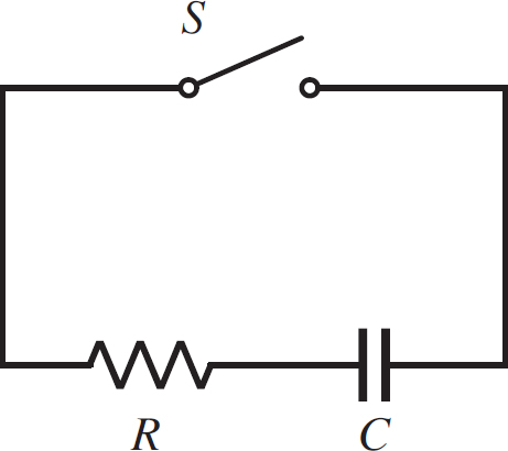
Figure 12.15: RC Circuit Without a Battery
In this RC circuit, there is no battery. The circuit element S is known as a switch, which is a break in the circuit that can be closed. When the circuit is broken, charges have no way of flowing, so nothing happens. Once you close the switch, and complete the circuit, charges can flow if there is a voltage to motivate them. In the RC circuit illustrated, let’s say that our capacitor is charged initially. What will happen in the circuit?
Well, before S is closed, nothing is happening. Once S is closed, the charges that are separated on the capacitor have a way of coming together. The electrons will leave the negative side of the capacitor and join the protons on the positive side, neutralizing both plates. Initially, if the charge is q0, then the voltage across the capacitor is q0/C. According to the loop rule, this means that the voltage across the resistor must also be equal to q0/C, so the initial current in the circuit is
i0 = 
So, what happens to this current? Well, as electrons move from the negative plate to the positive plate, the charge on the capacitor decreases. This means that the voltage across the capacitor decreases, and therefore the voltage across the resistor must decrease as well. Since the voltage across the resistor is dropping, the current in the circuit must be decreasing as well. So, the current continues dropping until the capacitor no longer has any charge left; then the current becomes zero. At any time during this discharging process, the current in the circuit is
Equation 12.12
i(t) = 
and the charge on the capacitor is
Equation 12.13
q(t) = 
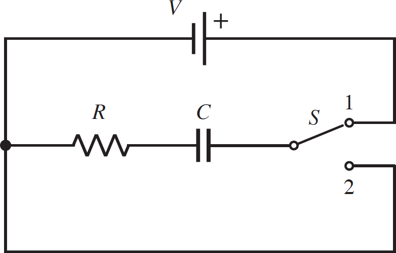
EXAMPLE 
In the following circuit, V = 5 V, R = 2 Ω, and C = 3 F. The capacitor begins uncharged, and the switch is moved into position 1. The switch remains in position 1 for 5 s and is then moved to position 2. What is the charge on the capacitor after the switch is in position 2 for 3 s?
First, you want to know how much charge is gained during the charging phase. This means that you will need Equation 12.11:
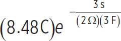
q(5s) = CV  = (3 F)(5 V)
  = 8.48 C
This will be our initial charge for the discharging step. During the discharging phase, the charge on the capacitor is given by Equation 12.13:
q(3s) =  =
=  = 5.14 C

Lesson 12.6
Applying Kirchhoff’s Loop Rule
Everything we have done so far has used Kirchhoff’s Loop Rule but in more of a qualitative sense. We’ve said that we know that the voltage around a loop is zero, but we’ve relied on the concepts of equivalent resistance and equivalent capacitance to solve complex circuit problems. However, there are going to be cases in which you cannot reduce your circuit to a single resistor or a single capacitor (or both, as in an RC circuit) because the connections of these hypothetical resistors and capacitors aren’t series or parallel, and we’re left with no way of forming equivalent resistors or capacitors.
Kirchhoff’s Loop Rule is not just a qualitative statement, but is also a mathematical statement. It states that, around a loop,
Equation 12.14
∑V = 0
So, as you trace your loop, you add up all of the voltages due to the different circuit elements and set it equal to zero. The voltage of a battery in a circuit will just be V, whatever its voltage happens to be; the voltage of a resistor in a circuit will be iR, as given by Ohm’s Law; and the voltage across a capacitor will be Q/C. However, in order for everything to sum to zero, clearly there has to be a mixture of positive signs and negative signs. When is a voltage positive, and when is it negative? Let’s go through this conceptually and then we’ll discuss how to apply Kirchhoff’s Loop Rule quantitatively to solve circuit problems.
Let’s start with a battery. A battery has a positive terminal and a negative terminal, and the polarity of the battery is the direction from the negative terminal to the positive terminal. Let’s look at the following figure.
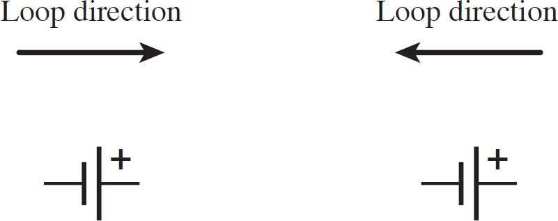
Figure 12.16: Loop Rule for a Battery
In this figure, we have two options for the loop direction: with the polarity and against the polarity. If the loop goes with the polarity, then the change in potential is positive, so the voltage is positive. If the loop goes against the polarity, then the change in potential is negative, so the voltage is negative. This is how you determine the sign of the voltage for a battery when applying the loop rule.
Now let’s discuss resistors. Let’s look at the following figure.
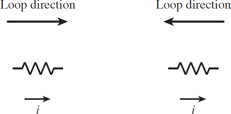
Figure 12.17: Loop Rule for a Resistor
We know that current moves from a high potential to a low potential (current is in the direction of the flow of positive charges; the actual electrons are moving in the opposite direction, from a low potential to a high potential). So if the loop goes in the same direction as the current, then the change in potential across the resistor is negative (from high to low), and so the voltage is negative. If the loop goes against the current, the change in the potential is positive, and so the voltage is positive. This is how you determine the sign of the voltage for a resistor when applying the loop rule.
Finally, we need to discuss capacitors. Capacitors have a polarity like a battery. In fact, a battery is just a capacitor with an infinite charge, as mentioned before. So the rules governing the sign of the voltage in the loop rule are the same for capacitors as they are for batteries.
EXAMPLE 
The following circuit is known as Wheatstone bridge, which is used to measure unknown resistances. It does so by varying one of the resistances until the current through the bridge (in this case, represented by the resistor R5) is zero, a process referred to as “balancing.” Let’s say that the bridge is balanced for R1 = 2 Ω, R2 = 1 Ω, R3 = 5 Ω, and R5 = 4 Ω. What is the value of R4?

First, let’s say that the current produced by the battery is i and the current through a resistor Rj = ij. The current i leaves the positive terminal of the battery and reaches the top of the bridge, splitting into i1 and i2, both traveling down the bridge. i1 reaches the junction at the middle of the bridge and becomes i5 and i3. When i2 reaches the middle of the bridge, it becomes i4 and i5. Leaving the bridge, i3 and i4 combine to form i again. You know that i1 through i4 are all going down the bridge, but i5 can go either left or right. In this case, you want to balance the bridge, meaning i5 will be zero, so it doesn’t matter which way you think it goes.
Applying the junction rule at the two midpoints on the bridge, you have
i1 = i3
i2 = i4
Note that i5 doesn’t appear because it is zero. Now you want to apply Kirkchhoff’s Loop Rule. Consider the upper triangle and the lower triangle of the bridge as loops. For both, use clockwise loops. (The direction of the loop is irrelevant; just choose a direction and go with it.) For the upper triangle, the loop goes against the current through R1, but with the current through R2. This means that the voltage across R1 is positive and the voltage across R2 is negative for this loop, or
V1 + V2 = i1R1 − i2 R2 = 0 → i1R1 = i2R2
For the lower triangle, the loop goes with the current through R4 and against the current through R3, so the voltage across R4 is negative and the voltage across R3 is positive for this loop:
V3 + V4 = i3R3 − i4R4 → i3R3 = i4R4
Make substitutions on the above equation using the junction rule results. Replacing i3 with i1, and i4 with i2, our above equation becomes
i1R3 = i2R4
Divide this equation by the equation for the first loop:

DRILL
CHAPTER 12 PRACTICE QUESTIONS
Click here to download a PDF of Chapter 12 Practice Questions.
Directions: Complete the following problems as specified by each question, and then check your work using the solutions that follow. For extended, step-by-step solutions, access your Student Tools online.
1. You have two cylindrical pieces of copper. One is short and fat while the other is long and thin. Which piece of copper has a higher resistivity? Which piece has a higher resistance?
2. You set up an experiment to measure the amount of charge entering a piece of copper in a certain amount of time. The copper is cylindrical with a radius of 2 cm and a length of 10 cm. You measure that 5 C of charge enters the piece of copper in 2 s. Answer the following questions. Note that the resistivity of copper is 1.68 × 10⁻⁸ Ω m.
(a) What is the current through this piece of copper?
(b) What is the resistance of this piece of copper?
(c) What is the voltage across this piece of copper?
(d) What is the electric field within this piece of copper?
3. A resistor is connected to a battery by conductive wiring, forming a circuit. If the battery’s voltage is 5 V, and it produces a current of 3 A, what is the resistance in the circuit?
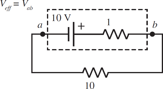
4. A 10 Ω resistor is connected to a battery with an internal resistance of 1 Ω. If the idealized voltage of the battery is 10 V, what is the effective voltage of the battery? This situation is diagrammed in the following figure.
5. A 10 Ω resistor is connected to a 5 V battery. What is the change in potential energy that an electron passing through the resistor undergoes? Note that the charge of an electron is −1.6 × 10⁻¹⁹ C.
6. An incandescent bulb is about 10% efficient, meaning about 90% of the energy dissipated by it is dissipated as heat and only about 10% as light. If you can treat a light bulb as a simple resistor connected to your outlet (which is at 120 V), what resistance of the light bulb is needed to produce 100 W of light?
7. What is the voltage of the battery in the following circuit if the current through the 2 Ω resistor is 1 A?

8. What is the current through the 5 Ω resistor in the following circuit?

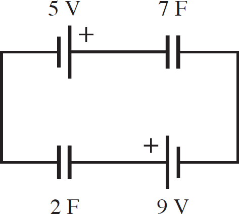
9. What is the charge on each capacitor in the following circuit?
10. A 9 F capacitor and 20 Ω resistor are connected in series to a 5 V battery, that has an open switch in the circuit. If the battery is initially uncharged, how long after the switch is closed does it take the current to drop by 50%?
SOLUTIONS TO CHAPTER 12 PRACTICE QUESTIONS
1. The resistivity is the same for both pieces of copper. Resistivity depends upon the material chosen, not the dimensions of the conductor. Resistance is proportional to length, but inversely proportional to area. This means that the resistance of the short, fat resistor is lower than the resistance of the long, thin wire.
2. (a) If 5 C moves through the copper in 2 s, then the current is
i = ![]() = 2.5 A
= 2.5 A
(b) The resistance is given by Equation 12.3:
R = ρ = = (1.68 × 10⁻⁸Ω m)  = 1.34 × 10⁻⁶ Ω
(c) The voltage is given by Ohm’s Law:
V = iR = (2.5 A)(1.34 × 10⁻⁶ Ω) = 3.35 × 10⁻⁶ V
(d) The electric field is just the voltage over the length of the copper cylinder:
E =  = 3.35 × 10⁻⁵
3. If the battery’s voltage is 5 V, then the voltage across the resistor is also 5 V due to the loop rule. This means that the resistance, given by Ohm’s Law, is
R =  = 1.67Ω
4. You can combine the two resistors into a single, equivalent resistor. Since they are in series, use Equation 12.7:
Req = 1 Ω + 10 Ω = 11 Ω
This means that the current in the circuit is
i = 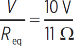 = 0.91 A
Now, to find the voltage from a to b, consider a line from a to b. Though you aren’t considering a loop, the rules about the signs of voltage along a line are the same. A loop is just a line that begins and ends at the same place. The voltage of the battery is positive because this line goes with the polarity, but the voltage due to the 1 Ω resistor is negative because the line goes with the current through that resistor. Thus,
Veff = Vab = 10 V − (0.91 A)(1 Ω) = 10 V − 0.91 V = 9.1 V
5. Since the battery’s voltage is 5 V, the voltage across the resistor is 5 V. This means that the change in potential energy of an electron going through the resistor is
ΔU = (−1.6 × 10⁻¹⁹ C)(5 V) = −8 × 10⁻¹⁹ J
It doesn’t matter how you choose to apply your signs here, the answer has to be negative. The electron is going to be moving through the circuit to decrease its potential energy, so ΔU has to be negative.
6. If you want the light bulb to emit 100 W of light, it actually has to be consuming energy at 1000 W, because it is only 10% efficient at converting electrical energy into light. If we treat this light bulb as a resistor connected to a 120 V power source, then the resistance has to be (by Joule’s Law)
P =  → R =
→ R = 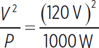 = 1.44Ω
7. If the current through the 2 Ω resistor is 1 A, then the voltage across this resistor is (2 Ω)(1 A) = 2 V. Furthermore, if the current through the 2 Ω resistor is 1 A, then the current through the 1 Ω resistor has to be 2 A. This is due to the fact that their voltages have to be the same, due to the loop rule. This means that the current entering the loop has to be 1 A + 2 A = 3 A. So, the voltage of the 4 Ω resistor has to be (4 Ω)(3 A) = 12 V. So, if the voltage of the loop is 2 V, and the voltage of the 4 Ω resistor is 12 V, then the voltage of the battery has to be equal to
Vbat = Vwire = 12 V + 2 V = 14 V
8. First, let’s call this current in the upper wire to be i1, the current through the middle wire to be i2, and the current through the lower wire to be i3. i1 is clearly going to the right and i2 is clearly going to the left, but you cannot predict which way i3 will point, so you have to guess. If you get a positive answer, then your guess was correct. If you get a negative answer, then your guess was wrong. Let’s guess that i3 goes to the right in the lower branch. This means that, at either junction,
i2 = i1 + i3
Let’s consider two loops: the upper loop and the outer loop. In both cases, we will use clockwise loops. In the upper loop, the loop with polarity of the 5 V battery, the voltage is positive, with the current through the 2 Ω resistor, so the voltage is negative, with the polarity of the 6 V battery, the voltage is positive, and with the current through the 6 Ω resistor, the voltage is negative. Putting this all together, the equation for the upper loop is
5 V − i1 (2 Ω) + 6 V − i2 (6 Ω) = 0
Now, for the outer loop, the loop goes with the polarity of 5 V battery, so the voltage is positive, with the current of the 2 Ω resistor, the voltage is negative, and against the current through the 5 Ω resistor, the voltage is positive. This means that the equation for the lower loop is
5 V − i1 (2 Ω) + i3 (5 Ω) = 0
Start with the upper equation. Use the junction rule equation to replace i2:
0 = 5 V − i1 (2 Ω) + 6 V − i2 (6 Ω) = 11 V − i1 (2 Ω) − (i1 + i3)(6 Ω) = 11 V −i1 (2 Ω) − i3 (6 Ω) = 11 V − i1 (8 Ω) − i3 (6 Ω)
This means that
i1 (8 Ω) = 11 V − i3 (6 Ω) → i3 = 1.38 V − 0.75i1
Make the above substitution in the equation for the outer loop:
0 = 5 V − i1 (2 Ω) + i3 (5 Ω) = 5 V − (1.38 V − 0.75i3)(2 Ω) + i3 (5 Ω) = 5 V − 2.76 V + i3 (1.5 Ω) = 2.24 V + i3 (6.5 Ω)
So, finally, current i3 is
i3 (6.5 Ω) = −2.24 V → i3 = −0.34 A
The negative sign simply means that we got our guess as to the direction of i3 wrong. It points to the left, not to the right. Go through on your own and find i1 and i2. They should be 1.64 A and 1.29 A, respectively.
9. This circuit may not look like it, but it is two batteries in series and two capacitors in series. The two capacitors in series combine to form an equivalent capacitor of capacitance
Ceq =  = 1.56F
Notice that if you were to draw a path from the 5 V battery to the 9 V battery, the path is with the polarity for both batteries. This means that their voltages sum, so the total source voltage is 5 V + 9 V = 14 V. This means that the charge on the equivalent capacitor is
Qeq = (1.56 F)(14 V) = 21.8 C
Since the equivalent capacitor was made from two capacitors in series, both the 7 F and the 2 F capacitors have 21.8 C of charge.
10. You know the current in the circuit is
i(t) = 
Recall that the initial current, i0, is V/R. So, you can express the ratio of the current at time t to the initial current as

If the current decreased by 50% at time t, then i0/i = 0.5. So, all you need to do is solve for t in the above equation:
0.5 =  → In (0.5) = -
  → t = -RC In (0.5) = 124.8s
REFLECT
Congratulations on completing Chapter 12!
Here’s what we just covered.
Rate your confidence in your ability to:
• Explain the basics of circuits, including the variables current, resistance, and voltage
1 2 3 4 5
• Explain Kirchhoff’s circuit rules
1 2 3 4 5
• Apply Kirchhoff’s circuit rules to circuits with resistors in them
1 2 3 4 5
• Apply Kirchhoff’s circuit rules to circuits with capacitors in them
1 2 3 4 5
• Apply Kirchhoff’s circuits rules to circuits with both resistors and capacitors in them
1 2 3 4 5
If you rated any of these topics lower than you’d like, consider reviewing the corresponding lesson before moving on, especially if you found yourself unable to correctly answer one of the related end-of-chapter questions.