14
Network and Internet of Things Programming
The Internet, in what has been called the Internet of Things, is starting to go beyond browsers and web servers to include Internet-enabled hardware. Printers, home automation devices, and even refrigerators are not only becoming smart, but also being connected to the Internet. And Arduino is at the forefront of DIY Internet devices using either a wired connection to an Ethernet Shield or a WiFi connection. In this chapter, we look at how to program an Arduino (or compatible board such as the ESP8266 or ESP32) to make use of a network connection.
The official Arduino solutions to WiFi are expensive and not much used, and so when it comes to WiFi, this chapter mostly focuses on the ESP8266 and ESP32 devices such as the NodeMCU, Wemos D1 Mini, and LOLIN32.
Networking Hardware
You have a number of choices for connecting your Arduino to the network. You can use an Ethernet Shield with an Arduino Uno or an Arduino with built-in Ethernet hardware, or more likely, avail yourself of an Arduino-compatible board with built-in WiFi.
Ethernet Shield
As well as providing an Ethernet connection, the Ethernet Shield (Figure 14-1) also provides a microSD card slot, which you can use to store data (see “Using SD Card Storage” in Chapter 7).

Figure 14-1 Ethernet Shield.
The W5100 chip is used in the official boards; you can also find much lower-cost Ethernet Shields that use the ENC28J60 chipset. These less expensive boards are not compatible with the Ethernet library, however, and are frankly best avoided unless you have more time than budget.
Arduino Ethernet/EtherTen
An alternative to using a separate shield is to buy an Arduino with built-in Ethernet capability. The official version is the Arduino Ethernet, but a worthy and Uno-compatible third-party board is the EtherTen produced by Freetronics (www.freetronics.com). This board is shown in Figure 14-2.

Figure 14-2 An EtherTen board.
Combining everything onto one board makes a lot of sense when building a networked Arduino project. The Arduino Ethernet can also be fitted with a Power over Ethernet (PoE) adapter that, with a separate PoE injector, allows the board to be powered from an Ethernet lead, reducing the wires needed for the Arduino to be just a single Ethernet lead. The EtherTen board comes already configured to use PoE. For more information on using PoE with an EtherTen, see www.doctormonk.com/2012/01/power-over-ethernet-poe.html.
The Ethernet Library
The Ethernet library has undergone a major revision since the release of Arduino 1.0 in 2011. In addition to allowing an Ethernet-equipped Arduino to act as either a web server or a web client (sending requests like a browser), the library also handles things like Dynamic Host Configuration Protocol (DHCP), which automatically assigns an IP address to the Arduino.
NOTE The official Arduino documentation on the Ethernet library is actually very good: http://arduino.cc/en/reference/ethernet.
Making a Connection
The first step, before any communication can take place, is to establish a connection from the Arduino to your network. The library function is called Ethernet.begin(). You can manually specify the connection settings for the board using the following syntax:
Ethernet.begin(mac, ip, dns, gateway, subnet)
Let’s look at each of these parameters in turn:
• mac The mac address of the network card (I’ll explain this in a moment.)
• ip The IP address of the board (You have to select one acceptable to your network.)
• dns The IP address for a Domain Name Server (DNS)
• gateway The IP address for the Internet gateway (your home hub)
• subnet The subnet mask
This syntax looks a little daunting unless you are used to manual network administration. Fortunately, all the parameters except mac are optional, and 90 percent of the time, you will either specify mac and ip or, most likely, just the mac on its own. All the other settings are taken care of automatically.
The MAC, or Media Access Control, address is a unique identifier for the network interface; in other words, it’s the address for the Ethernet Shield or for whatever is providing the network interface for the Arduino. This strange-looking code only has to be unique for your network. You’ll usually find this number printed on the back of your Arduino Ethernet Shield or on the box packaging. If you are using an older board that does not have a MAC address, then you can simply make one up. However, do not use the same made-up number more than once on your network.
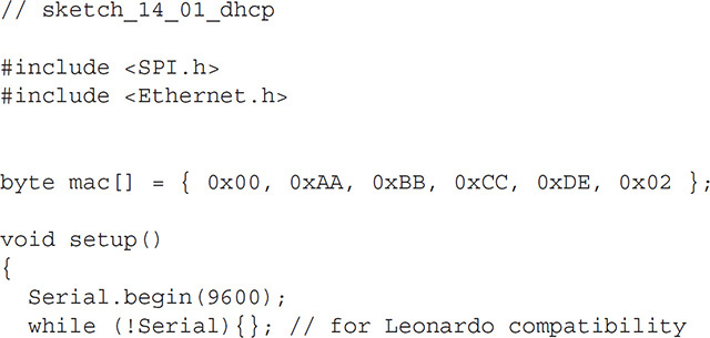
You can also create a network connection using DHCP so the IP address is allocated dynamically; use this code:


If you want to fix the IP address, which would be desirable if you wanted to run a web server on the Arduino, then you would use code like this:
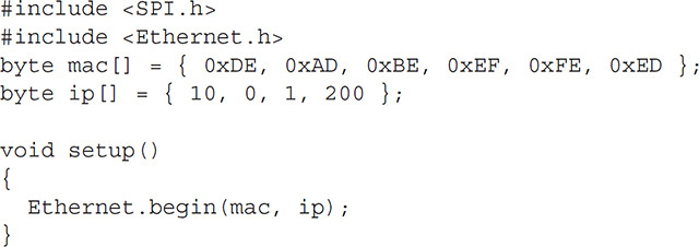
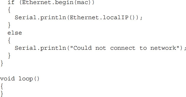
You need to ensure that the IP address you use is acceptable to your network and not in use by another device. Your router may also reserve certain IP addresses for other uses. If you do not specify an IP address and use DHCP, then Ethernet.begin will return 1 if a connection is made and an IP address allocated; otherwise, it returns a 0. You can incorporate a test in which you make the connection and use the localIP function to retrieve the IP address allocated to the Arduino. The following example performs this test and reports the status to the Serial Monitor. This is a full sketch that you can try for yourself. But before you do, remember to change the MAC address in the code to match that of your interface board.
Setting Up a Web Server
The project “Physical Web Server,” described later in this chapter, illustrates the code structure of a web server sketch. In this section, we’ll look at the available web server functions.
The EthernetServer class contains most of the functions that you need for web serving. Having established a connection to the network, starting a web server requires two further steps. First, you need to create a new server object, specifying the port that the server should be listening on. This declaration appears in the sketch before the setup function.
EthernetServer server = EthernetServer(80);
Web pages are usually served on port 80. So if you start the web server on port 80, you will not need to add a port number to any URL that connects to the server.
Second, to actually start the server, you use the following command in your setup function:
server.begin();
This function starts the server, and it will now be waiting for someone with a browser to request the web page that it is serving. This action is detected in the loop function of your sketch using the available function. This function returns either null (if there are no requests to service) or an EthernetClient object. This object is rather confusingly also used when making outgoing requests from the Arduino to web servers. In either case, EthernetClient represents the connection between a web server and a browser.
Having retrieved this object, you can then read the incoming request using read and you can write HTML to it using the write, print, and println functions. Once you’ve finished writing the HTML to the client, you need to call stop on the client object to end the session. I explain how to do this in “Physical Web Server” later in this chapter.
Making Requests
In addition to having the Arduino act as a web server, you can also have it act like a web browser, issuing HTTP requests to a remote web server, which may be on your own network or on the Internet.
When making web requests from the Arduino, you first establish a network connection in just the same way that you did in the previous section for the web server, but instead of creating an EthernetServer object, you create an EthernetClient object:
EthernetClient client;
You do not need to do anything more with the client object until you want to send a web request. Then you write something like this:
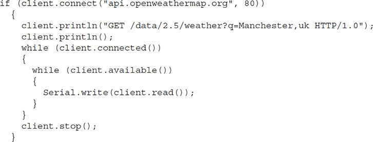
The connect function returns true if the connection is successful. The two client.println commands are responsible for requesting the desired page from the web server. The two nested while loops then read data as long as the client is connected and data is available.
It may look tempting to combine the two while loops, with a condition of client.available() && client.connected(), but combining them is not quite the same as treating them separately, as the data may not be available continuously from the web server because of connection speed and so on. The outer while loop keeps the request alive, fetching the data.
This approach is “blocking” (the Arduino will not do anything else until the request is complete).
Wired Ethernet Examples
The following two examples serve to illustrate the use of the Ethernet library in practical settings. Between the two of them, the examples cover most things that you are likely to want to do with a networked Arduino.
Physical Web Server
This first example illustrates perhaps the most likely web-related use of an Arduino. In it, the Arduino acts as a web server. Browsers connecting to the Arduino web server not only see readings from the analog inputs, but visitors can also press buttons on the web page to change the digital outputs (Figure 14-3).
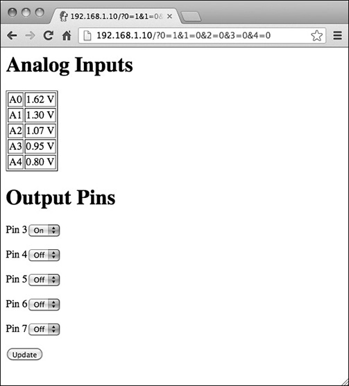
Figure 14-3 Physical web server interface.
This example is actually a great way to interface an Arduino with a smartphone or tablet computer, as a device only has to have the most basic of browsers on it to be able to send requests to the Arduino. The sketch for this example (sketch_14_02_server—available for download from the book’s website at http://simonmonk.org/nextsteps2/) is some 172 lines long, so rather than list it in full here, I encourage you to load it in the Arduino IDE for reference as I walk you through it.
The first part of the sketch is pretty standard for a network sketch. The libraries are imported, and both EthernetServer and EthernetClient objects are defined.
The variables in the next section perform various roles:
const int numPins = 5;
int pins[] = {3, 4, 5, 6, 7};
int pinState[] = {0, 0, 0, 0, 0};char line1[100];
char buffer[100];
The constant numPins defines the size of the arrays pins and pinState. The pinState array is used to remember whether the particular output pin is HIGH or LOW. The setup function declares all the pins in the pins array to be outputs. It also establishes the network connection in the same way as in the earlier examples. Finally, the line1 and buffer character arrays hold the first line of the HTTP request and subsequent lines, respectively.
Here is the loop function:

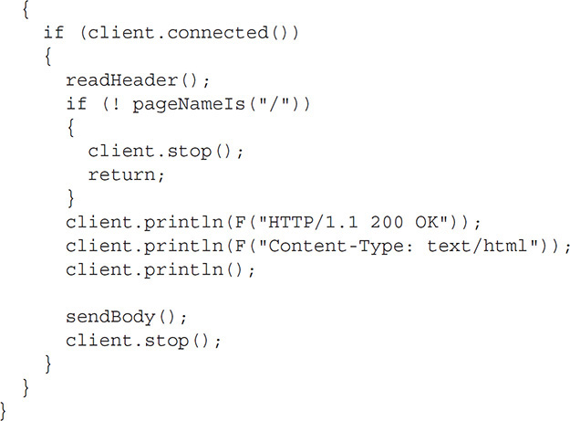
The loop function checks to see if there are any requests from browsers waiting to be processed. If there is a request and there is a connection, then the readHeader function is called. You’ll find the code for this toward the end of the sketch. The readHeader function reads the contents of the request header into a buffer (line1) and then skips over the remaining lines of the header. This is required so you have access to the page name (requested by the browser) as well as any request parameters.
Note that because the sketch has a fair amount of text to send to the Serial Monitor and network, I use the F function to store the character arrays in flash memory (see Chapter 7).
Having read the header, the pageNameIs function (again near the end of the file) is called to ensure the page being requested is the root page (/). If it is not the root page, then the request is ignored. This is important because many browsers automatically send a request to a server to find an icon for the website. You don’t want this request being confused with other requests to the server.
Now you need to generate a response in the form of a header and some HTML to be returned to the browser for display. The sendBody function, shown here, gets a little complicated:

This function prints the basic template of the HTML page, relying on a number of helper functions to break the code down into more manageable chunks. The first of these is sendAnalogReadings:
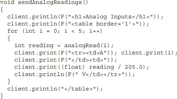
This loops over each of the analog inputs, reading the value and writing out an HTML table containing all the readings as voltages.
You may have noticed that the sendBody function also calls setValuesFromParams and setPinStates. The first of these uses the function valueOfParam to set the pinStates variable containing the states of the output pins HIGH or LOW depending on the value of the request parameters that were contained in the request header:

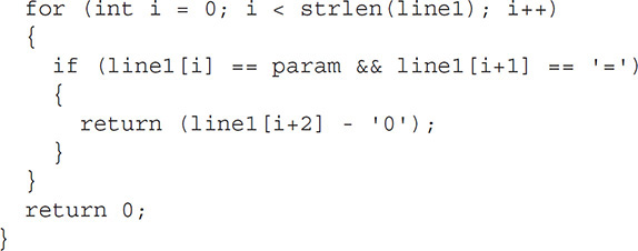
The valueOfParam function expects the request parameter to be a single digit (1 or 0). You can see what these parameters look like if you run the example and browse to the page and press Update. The URL string will then change to include the parameters and look something like this:
192.168.1.10/?0=1&1=0&2=0&3=0&4=0
The parameters start after the ? and take the form X=Y, separated by &. The part before the = is the parameter name (in this case, a digit from 0 to 4) and the part after the = is its value, which is 1 for on and 0 for off. To make life easy for yourself, these request parameters must be only a single character or, in this case, a single digit. The setPinStates function then transfers the state of the output pins held in the pinStates array to the actual output pins themselves.
Let’s return to the sendBody function for a moment. The next thing that you need to send is the HTML for the collection of drop-down lists for each output. You need the values of True or False in the list to be set to agree with the current state of the output. You accomplish this by adding the text “selected” to the value that agrees with the value for that pin in the pinStates array.
All the HTML generated for the output pins is contained within a form, so when a visitor presses the Update button, a new request to this page with the appropriate request parameters to set the outputs is generated. At this point, let’s look at the HTML code that is generated for the page:


You can see this using your browser’s View Source feature.
Using a JSON Web Service
To illustrate sending a web request from an Arduino to a website, I’ll use a web service that returns data about the weather in a particular location. It reports a short description of the weather to the Serial Monitor (Figure 14-4). The sketch sends the request once during startup, but the example could easily be changed to check every hour and display the result on a 16×2 LCD display.
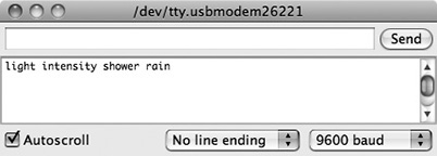
Figure 14-4 Retrieving weather information from a web service.
JavaScript Object Notation (JSON) is a way of structuring data returned from a web request. You can find out more about the JSON format here: https://en.wikipedia.org/wiki/JSON.
Before you can use the web service, you will need to apply for an API key. This is free, so long as you stay under 60 requests per minute. To get yourself a key, go to https://openweathermap.org/appid and click the “Sign up” button. Once you have your key (a long string of letters and numbers) keep the page open so that you can copy and paste it into the function doWebRequest in the sketch_14_03_web_request.
This example program uses the ArduinoJson library that you will need to add using the Library Manager.
The sketch for this example is quite short (sketch_14_03_web_request). Most of the interesting code is in the functions doWebRequest and parseAndPrintWeather:

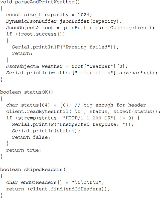
The first step is to get the client to connect to the server on port 80. If this is successful, then the page request header is written to the server.
The extra println (after the GET line is sent) is needed to mark the end of the request header and trigger a response from the server.
The function parseAndPrintWeather is only called if the client is connected and both the functions statusOK (which checks the HTTP response status) and skippedHeader (skips the headers so that it is not parsed as JSON) return true.
The code to parse the response in parseAndPrintWeather is partly automatically generated using a web-based tool provided by the developers of the ArduinoJson library available at https://arduinojson.org/assistant/ (Figure 14-5). Simply paste an example response from the web service you need to access into the "Input" panel and the assistant will give you a suggested size of buffer as well as example code at the bottom of the screen.
The data is in JSON format as shown below.

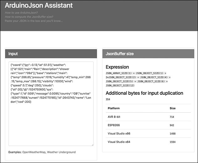
Figure 14-5 The ArduinoJson Assistant.
The Official Arduino WiFi Library
As you might expect, the WiFi library is quite similar to the Ethernet library. If you substitute WiFi for Ethernet, WiFiServer for EthernetServer, and WiFiClient for EthernetClient, then everything else in your sketch can pretty much stay the same.
Making a Connection
The main differences between the WiFi and Ethernet libraries are in how a connection is established.
First, you need to import the WiFi library:
#include <SPI.h>
#include <WiFi.h>
To establish a connection, use the WiFi.begin command, supplying it with the name of your wireless network and your password.
WiFi.begin("MY-NETWORK-NAME", "mypassword");
The WiFi example that follows in “Arduino WiFi Example” illustrates the other differences that you need to be aware of.
WiFi-Specific Functions
The WiFi library has some extra WiFi-specific functions that you can use. These functions are summarized in Table 14-1.
You can find full documentation for the WiFi library here: http://arduino.cc/en/Reference/WiFi.

Table 14-1 WiFi-Specific Features
Arduino WiFi Example
For the example, I modified sketch_14_02_server to work with a WiFi Shield, should you choose to use one rather than the cheaper ESP8266 and ESP32 alternative. You can find the code in sketch_14_04_server_wifi. Rather than repeat the whole example, I will just highlight the changes from the original version.
First, to make the connection to a wireless access point, you need to specify the name of the wireless network and its password:

You also need to change the names of the classes for the server and client from EthernetServer and EthernetClient to WiFiServer and WiFiClient:
WiFiServer server(80);
WiFiClient client;
You still need to specify port 80 when defining the server.
The next difference between wired Ethernet and WiFi is at the point where the connection starts. In this case, you must use
WiFi.begin(ssid, pass);
The remainder of the code is almost exactly the same as the Ethernet code. You will find a delay(1) command in loop before the client is stopped, which gives the client time to finish reading before the communication is closed. You don’t need this in the Ethernet version. You’ll also notice that I combined some of the client.print calls into fewer calls of bigger strings. This speeds up the communication as the WiFi Shield deals with sending small strings quite inefficiently. However, be aware that the strings in an individual client.print or client.println cannot be longer than 90 bytes or they will not be sent.
The WiFi version of this program is considerably slower than the Ethernet version, taking up to 45 seconds to load. The firmware on the WiFi Shield can be updated, and if in the future the Arduino team improves the efficiency of the WiFi Shield, then it may be worth updating the firmware. Look for instructions for this on the WiFi Shield web page: http://arduino.cc/en/Main/ArduinoWiFiShield.
ESP8266/ESP32 WiFi Example
The ESP community has implemented the Arduino “WiFi” library so, in principle, standard Arduino examples will (sometimes with a little modification) work on ESP8266-based devices. However, the greater RAM and flash storage of the ESP8266 boards means that you can implement network projects in a more modern and elegant way if you diverge from the standard Arduino WiFi library.
The following example is a little like the Ethernet web server example we met earlier, but is designed to control a single output pin, perhaps connected to a relay module to switch high current loads (Figure 14-6). A simple web page (Figure 14-7) will allow the relay to be turned on and off.
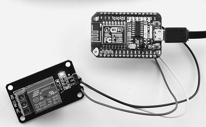
Figure 14-6 Using a relay module with a NodeMCU.
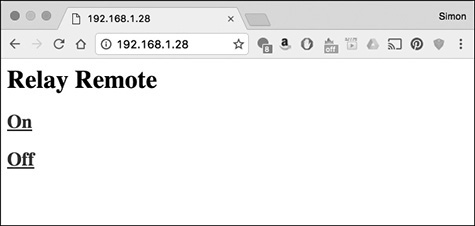
Figure 14-7 A web interface server by NodeMCU.
The code for this can be found in sketch_14_05_esp8266_server (available from the book’s web page here: http://simonmonk.org/nextsteps2/). The important difference between this sketch and sketch_14_02_server is that this sketch allows you to define “routes”—that is, it allows you to associate a requested page name with a function to run when a request comes in. This is done in the setup function:

In this case, the page specified is the root page (“/”) and the function to call when a request comes in for root is called handleRoot.

The first thing the handler does is use server.arg(0) to get the first request parameter as a string. The first character of this string is then compared with the character “1” to decide whether or not to turn the relay on.
The handler then formulates the HTML needed for the page in a string and sends the response.
Using this approach, you can specify as many handlers for different pages as you like. For example, to handle a request for the page relay_status to invoke the function handleRelayStatus, you could add the line:
server.on("/relay_status ", handleRelayStatus);
The call-back mechanism does require you to include a call to the method handleClient in your loop function.

The extra resources of an ESP8266-based board make it more suited to network applications than, say, an Arduino Uno with add-on hardware. With slight modification, this same example can be used on an even more powerful ESP32-based board like the LOLIN32. You will find an example of using the ESP32 in sketch_14_05_esp32_server.
Note that you will need to download the library ESP32WebServer as a ZIP file from https://github.com/Pedroalbuquerque/ESP32WebServer and then add it as a library in order for this sketch to work.
The code for ESP32 is almost identical to that of the ESP8266, except for different imports and a change to the pin used for switching to pin 22, which is connected to the built-in LED on the LOLIN32.
Internet of Things
Many of the examples in this chapter that use Arduino to send web requests or act as a web server are useful techniques when building Internet of Things (IoT) projects. In this section you will find a very simple example that uses a NodeMCU Arduino-compatible to send temperature readings to the dweet.io IoT service. A separate web page (that can just be a file on your computer) then displays the temperature readings. Figure 14-8 provides an overview of this project.
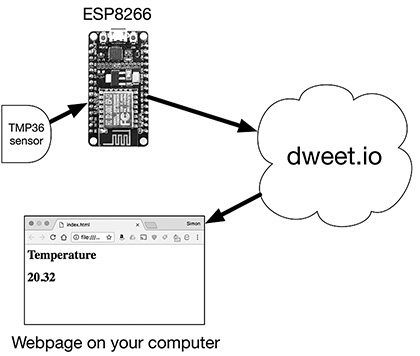
Figure 14-8 An Internet of Things project.
dweet.io
There are many IoT frameworks available (such as ThinkSpeak, OpenHab, or adafruit.io) that could be used for this project. However, dweet.io has the following advantages:
• It’s free (for home use).
• You don’t have to create a user account.
• It’s really easy to use.
dweet’s model is a bit like Twitter. In this case, a WiFi-enabled sensor is tweeting its temperature at regular intervals and then someone watching their Twitter feed (or dweet feed) sees the temperature remotely. It’s a good idea to test out dweet from your browser before we start writing code.
Let’s start by pretending to be a NodeMCU with a temperature sensor attached. Open your browser and paste the following line into your address bar:
http://dweet.io/dweet/for/next_steps_temp?temp=24
The phrase “next_steps_temp” is a “key” that identifies the type of message. You can put anything you like here, but you should make it unique; otherwise, your messages may get mixed up with someone else using the same key. There is no way of guaranteeing your key is unique and will stay unique, but making up, say, a long number to include in the key can make the chances of mix-ups vanishingly small.
When you send the request, you should see a response in your browser that looks something like this:

This is in JSON format and just confirms that the temperature information has been received. dweet will keep your last five dweets for any given day. You can request the last dweet from your browser by entering the following URL into your browser:
http://dweet.io/get/latest/dweet/for/next_steps_temp
This will give you a response something like:

The crucial thing to notice is that the temperature of “24” has been given back to us. So now, you just need to arrange for the NodeMCU to dweet temperature readings on a regular basis and then arrange a web page to regularly refresh itself with the latest temperature.
Programming the NodeMCU or Wemos D1 Mini
You can find the sketch for this example in sketch_14_07_esp8266_iot.
Before using this example, you should edit the sketch, changing the thingName from next_steps_temp, perhaps adding your name to the end to make it more likely to be unique.
The connection code is much the same as the earlier examples in this chapter. The function sendTemp takes care of sending out the HTTP request containing the temperature.
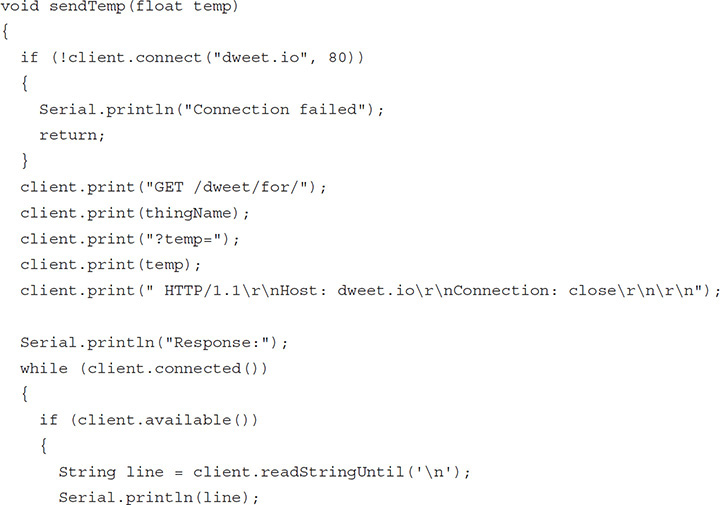

The client program first connects to the server at dweet.io and then sends the GET request to the server containing the temperature. As an aid to debugging, the response is sent to the serial monitor.
Attaching the TMP36
This example uses a TMP36 temperature. This sensor outputs a voltage proportional to the temperature. This output voltage is connected to the A0 analog input of the NodeMCU on solderless breadboard, as shown in Figure 14-9. This can be easily adapted for use with a Wemos D1 Mini.

Figure 14-9 Connecting a TMP36 to an ESP8266-based board.
A Web Page to Display the Temperature
If everything is connected up, your ESP8266 should now be sending temperature updates to dweet every 30 seconds. We now get to create the web page shown in Figure 14-10 to display the temperature.
Note that you do not need to host this page on a web server. It will work in your browser just fine as a file saved locally on your computer. You can find this file (index.html) inside the folder iot_page with the other downloads for this book (see the Introduction section before Chapter 1). The file index.html is listed below.

This is a book about programming Arduino, not HTML and JavaScript, so if you are new to web development, you might need to do a bit of reading-up.
The page is a mixture of JavaScript (contained in the <script> tags at the top) and HTML (contained in the <html> tag at the bottom of the page).
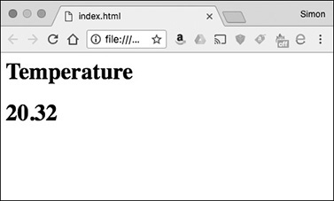
Figure 14-10 Displaying the temperature in a web page.
The first <script> tag imports the JQuery JavaScript library, which makes it much easier both to send web requests and to control the HTML displayed in your browser. The rest of the JavaScript consists of two functions. The function get_temp sends the web request to fetch the latest dweet. Note that this contains the “thing name” key of next_steps_temp. You will need to change this to match whatever key you decided to use in your Arduino sketch. This get_temp function sets a callback, so that when the request receives a response, the second function (show_temp) will be run. This function changes the text attribute of the <h1> tag called <temp_tag> in the HTML at the bottom of the page.
To ensure that the page is automatically refreshed, the set_interval JavaScript command is used to run the get_temp function every five seconds.
Summary
In this chapter, you looked at a variety of ways to connect your Arduino or Arduino-compatible board to a network and then make it do something, using both Ethernet and WiFi Shields. You have also learned how to use an Arduino as both a web server and a web client.
In the next chapter, you’ll learn about Digital Signal Processing (DSP) with the Arduino.