
Cranksets and bottom brackets (BBs) on most performance bikes generally fall into two categories: a two-piece design, where the BB spindle is integrated into one arm of the cranks et, and the more traditional spindle-BB design, where the crankarms are attached to a spindle (usually square taper or splined) integrated into the BB.
Here, we’ll show you how to identify, maintain, and overhaul a variety of both types of designs. Enjoy!
• CRANKSET AND BOTTOM BRACKET BASICS
• REMOVE AND INSTALL A SHIMANO TWO-PIECE CRANKSET
• REMOVE AND INSTALL SRAM AND TRUVATIV GXP CRANKSETS
• REMOVE AND INSTALL AN FSA EXTERNAL CRANKSET
• REMOVE AND INSTALL CAMPAGNOLO OVER TORQUE CRANKSETS
• REMOVE AND INSTALL CAMPAGNOLO AND FULCRUM ULTRA-TORQUE CRANKSETS
• INSTALL A SEALED-BEARING CARTRIDGE-STYLE BOTTOM BRACKET
• CHAINRING MAINTENANCE
• CRANKSET MAINTENANCE
• TROUBLESHOOTING CRANKSETS AND BOTTOM BRACKETS

External or two-piece: A modern standard used with two-piece cranksets; the bearing cups sit outside the BB shell, and the spindle is part of the cranks. This is the most common design on new bikes.

Square taper: An older-style crank interface; easy to spot with the four-sided crank interface.

ISIS: A splined standard agreed upon by a number of manufacturers, including Race Face (shown here).
1. Loosen the two pinch bolts on the left crankarm with a 5-millimeter hex key. These bolts clamp the arm in place on the spindle.
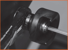
2. Use Shimano’s crankarm installation tool (TL-FC16), or Park Tool’s version of it (the BBT-9), to remove the preload cap by turning it counterclockwise. The left crankarm will slip easily off the spindle.

Step 2
3. Notice that there is a broad spline on the spindle and inside the crankarm, making it nearly impossible to misalign the left crankarm when you reinstall it. There is also a thin black rubber O-ring on the spindle between the bearing and crankarm. Remove this from the spindle and set it into its seat on the crankarm to keep track of it.
Step 3
4. The spindle will now smoothly slide out of the bottom bracket. If it’s not cooperating, give the end of the spindle a few light taps with a rubber mallet.
5. Remove the bottom bracket cups from the shell using an appropriate spanner. Shimano’s part number for this tool is TL-FC32; Park Tool’s BBT-9 will also work. Most road and mountain bikes today have an English-thread BB shell, so the left-side cup will come out when turned counterclockwise, but the right-side cup must be turned clockwise to remove it.

Step 5
Installation is as simple as reversing these steps. Don’t overtighten the preload cap that holds the left crankarm in place. This cap is intended only to snug the crankarm in place and should be only slightly more than finger-tight. Finally, tighten the pinch bolts incrementally to be sure they are both properly and evenly torqued.
1. To remove the left arm, loosen the crank-fixing bolt with an 8-millimeter hex key until you feel resistance again. At this point, the bolt is pushing outward. Continue turning the bolt counterclockwise until the arm frees itself from the spline on the spindle.
Step 1
2. With the left arm removed, you can slide the spindle out of the bottom bracket by pulling on the right crankarm. If it’s tight, gently tap it with a plastic mallet to free it.

Step 2
3. Notice that there is a change in diameter on the end of the spindle. This shoulder traps the left-side bearing against the left crankarm. This simple feature puts the task of stabilizing the crankset onto the left-side bearing, so the right-side bearing can float freely on the spindle with no side load. The floating design eliminates unnecessary drag in the system.
4. The cups are removed and installed in the same manner as any other external bottom bracket. Using a wrench for external-type BB cups, turn the left side counterclockwise to remove it. Turn the right-side cup clockwise to remove it.
The exception: Some Italian frames have Italian-threaded BB shells. If the bearing cup is marked with the word Italian, turns it counterclockwise, regardless of which side of the frame it occupies.

Step 4
5. Installation is simple. Clean the threads in the BB shell, lightly grease the threads on the cups, and determine whether spacers are necessary (for mountain bike cranksets) before threading the cups into the shell. If you have an Italian-threaded frame, be sure you check the cups and install the one marked “nondrive” on the left side of the frame. Otherwise, the spindle won’t fit correctly.
Position the chain so it won’t get trapped, then slip the spindle through the BB until it stops. Align the left crankarm on the spline and tighten the fixing bolt until the arm bottoms out on the left-side bearing. That’s it. Really.
1. FSA cranksets come in two varieties: Some models have pinch bolts to affix the left arm to the spindle, and some don’t.
If your crankset is a Gossamer model, it has pinch bolts on the left arm. Loosen the pinch bolts and then remove the preload cap from the face of the arm. With the preload cap removed, the arm should slide easily from the spindle.
2. SL-K model cranksets don’t have pinch bolts and instead rely on a precision-fit spline. The fixing bolt also functions as the extractor. Turn the bolt counterclockwise to loosen it. You’ll feel resistance again, but keep turning until the arm frees itself from the spindle.

Step 2
3. SL-K cranks have a wave washer on the spindle, between the left arm and the bottom bracket. Insignificant as it may look, this is a critical part for maintaining the proper bearing preload.
Step 3
Gossamer cranks sometimes also have a special washer. In this case, the washer is specific to the model of BB rather than to the crankset. You can find out which BB models require washers by consulting your local shop or checking out the tech documents on FSA’s Web site (www.fullspeedahead.com).
4. With the left arm removed, the spindle will slide out of the BB with a tug on the spider. If it’s snug, a few gentle taps with a plastic mallet will set it free.
Remove the cups from the BB shell by turning the left cup counterclockwise and the right cup clockwise (unless it’s Italian-threaded).
5. Installation begins by putting the cups back in. Make sure the threads in the bottom bracket shell are clean and free of burrs, lightly grease the threads on the cups, and determine whether spacers are necessary before threading the cups into the shell.
If your Gossamer-type crank and bottom bracket combination requires crush washers, make sure one is installed on the spindle. Push the spindle through the BB until the right arm butts against the right-side bearing. SLK-type cranks do not require a washer on the right side.
6. Before installing the left arm, put the wave washer (SLK) or crush washer (if necessary for your Gossamer crank-BB) on the exposed end of the spindle.

Step 6
7. For SLK models, align the left arm on the end of the spindle and tighten it in place with the fixing bolt. At this point, SLK cranks are fully installed.
A Gossamer left crankarm will slip onto the spindle by hand. Once it’s in place, install and snug the preload cap.
8. Finish the Gossamer crankset installation by tightening the pinch bolts. Tighten in small increments—one, then the other, and back to the first. Repeat this until both bolts are properly torqued.
1. Campagnolo Over Torque cranksets, introduced in late 2013, are similar to other two-piece cranksets in that a splined bottom-bracket spindle is attached to the drive-side crankarm, and adjustments are managed via the non-drive-side arm. However, a few key differences set Over Torque apart, and we’ll cover those differences here.
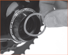
2. To remove the crankarm, first unlock the dowel on the clearance recovery ring (a small black ring between the left crankarm and the bottom bracket shell) using a 1.5-millimeter Allen wrench, and turn the ring counterclockwise to loosen it slightly.

Step 2
3. Now, use the crankarm removal tool (UT-FC130) to remove the lock ring around the center of the left-hand crank. The pins in the tool align with the holes in the ring; use an 8-millimeter Allen wrench to turn the tool and remove the ring.
Step 3
4. Use the other side of the tool to remove the crankarm itself. First, back out the inner drum so that you can easily slide the tool over the crankarm without scratching it. Slide the tool in place over the crankarm, then use an 8-millimeter Allen wrench to tighten the exterior bolt on the tool. Turning the tool in will force the crankarm off the bottom bracket spindle. Once it’s off, loosen the bolt to remove the crankarm from the tool. Slide off the clearance recovery ring, and then pull the drive-side crankarm out from the bottom bracket, keeping track of any spacers used to match your bottom bracket width.

Step 4
5. Installation follows the same basic steps but in reverse and using the UT-FC220 installation tool. Put a light coating of grease on the gaskets of the bottom bracket cups, and put any necessary spacers in place (you kept track when you removed the BB, didn’t you?).
6. Position the clearance recovery ring on the non-drive-side spindle, with the teeth of the ring facing out. Put a coating of grease on the end of the spindle and inside the crankarm, and put the crankarm in position on the spindle.
7. Put the installation tool (UT-FC220) in place (make sure the interior drum is protruding slightly) using a 5-millimeter Allen wrench. Then, using a 24-millimeter wrench or socket, tighten the tool until the end of the BB spindle is flush with the crankarm. Remove the tool with the Allen wrench.

Step 7
8. Fit the lockring, and use the UT-FC130 tool to tighten it in place. Use a torque wrench and tighten the lockring to 8 to 10 NM of force. Tighten the clearance recovery ring (between the left crankarm and the BB shell) to take out any remaining play—it should be only finger-tight—then turn the dowel with a 1.5-millimeter Allen wrench to lock it into position. Done.
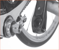
1. On Campagnolo and Fulcrum Ultra-Torque cranksets, the spindle is in two halves, each permanently affixed to a crankarm. A spline on the end of each spindle segment joins with the other in the center of the bottom bracket with a substantial bolt holding the assembly together. A 10-millimeter hex key on a 2-inch ratchet extender can reach inside the right side of the spindle to access the bolt.

Step 1
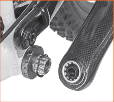
2. Removing the bolt frees the left arm for removal. Notice that the bearing is press-fitted onto the spindle, rather than into the cup, as is the case with other two-piece designs.
There is also a wave washer that fits inside the cup to preload the bearing.

Step 2
3. Remove the retaining clip from the right-side cup to remove the right arm and spindle segment. The clip is tricky to get at. Pull one side of the clip out with needle-nose pliers, then repeat on the other side. The right crankarm should slip out of the cup.

Step 3
4. Remove the cups from the BB shell as you would any other external-type cups. Turn the left-side cup counterclockwise and the right-side cup clockwise (unless it’s Italian-threaded).
Installation is a straightforward reversal of these steps. Make sure the threads in the BB shell are clean and free of burrs, and lightly grease the threads on the cups before threading the cups into the shell.
5. The Ultra-Torque spline should be liberally greased before pushing the right crankarm and spindle segment into the right-side BB cup.
6. Reinstall the retaining clip on the right-side BB cup. Insignificant as it may seem, the clip plays a crucial role by securely holding the right-side bearing in position in its cup, stabilizing the system so the crankset can’t float side to side in the BB. Floating can cause front shifting problems or possibly throw the chain.
7. Place the wave washer in the left-side BB cup and then slide the left crankarm and spindle segment into the cup. Be sure the splines align and engage properly, then prepare for a good arm workout.
Step 7
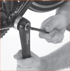
8. Put the crank-fixing bolt on the end of the extender, insert it into the right-side spindle, and tighten it until you feel the assembly bottom out.

Step 8
Note: There are many different sealed-bearing cartridge-style bottom bracket designs, with more coming along almost daily. If these instructions don’t match your BB, visit the manufacturer’s Web site for installation details.
1. Remove the old bottom bracket. It might be as easy as turning the cartridge out with the splined removal tool. Turn the left-side cup first, counterclockwise, until it comes out of the frame. Then turn the right-side cup clockwise to remove the cartridge.
If the cups won’t turn, don’t force them. Apply Liquid Wrench or a similar penetrating lubricant to the cup edges and tap the BB shell with a hammer to vibrate it, which should work the solvent into the threads. Wait a while and try to turn the cups again. Repeat this procedure until the cups unscrew, or take the bike to a shop for help.
Sealed cartridge BBs come from the factory packed with grease and adjusted. Before installing the new one, turn the spindle by hand to feel how the factory adjustment feels. Later, when it’s installed, the spindle should turn much as it does fresh from the box.
Cartridge bottom brackets usually have one cup preinstalled on the drive side of the cartridge. If the BB is being installed in a titanium frame, coat the threads with Finish Line Ti-Prep or some other anti-seize compound. Wrapping plumber’s Teflon tape around the threads of the cartridge and cup is also acceptable.
2. Treating the threads will prevent chronic clicking noises from the bottom bracket area and fight galvanic corrosion, which can freeze the BB into the shell. (Grease is usually adequate for steel and aluminum frames.)
Start threading the cartridge into the drive side of the frame by hand-turning it counterclockwise (see photo). Be careful not to cross-thread it.

Step 2
3. When the cartridge gets tough to turn, install the splined tool (see photo) and continue turning until the cup is snug and fully screwed into the frame (it’ll go only so far because of the built-in lip on the cup edge).

Step 3
4. Install the other cup (be careful not to cross-thread it), turning it clockwise with the splined tool until the cup bottoms against the cartridge. Check how things are going by turning the spindle by hand. If it’s a lot tighter than it was before installation, it’s likely that the cup is going in crooked. Remove it and start again, making sure it’s straight. When the cup is secure, check the installation by putting the splined tool on the drive side again and making sure it’s tight, then double-check the tightness of the left-side cup. Finally, grab the spindle and turn it. It should feel smooth, like it did before installation. If not, try again.
When the bottom bracket is installed correctly, attach the crankarms. Remember to snug the bolts after the first ride and monthly thereafter.
1. Keep them clean. At least once a month—more often if you do a lot of riding on wet and dirty terrain—take a rag and wipe your chainrings clean. Dampen the rag with a little solvent, if you need to, or use a stiff brush to loosen the grime so it can be wiped away. Clean your chain at the same time, or this work will be for nothing. See this page for instructions.
2. Keep them straight. Straightening a bent chainring can be managed with a hammer or the help of a chainring bending tool. This is a simple tool, one that is less expensive than most specialized bike tools. To pry out a bent tooth or an extreme bend in a ring, you can also use an adjustable wrench after tightening the jaws enough that they just slip over the ring.
3. Check for wear. If you see shiny cuts on the sides of the chainring teeth, it means you’re riding in gear combinations that force the chain into extreme angles. One extreme occurs when you ride with the chain on the large chainring and the largest inner cog. Another results from the chain being shifted onto the inner chainring and the smallest rear cog.
4. Replace as needed. Replacing worn chainrings is usually an easy process. Normally, they’re attached with hex key bolts to a five-armed spider that radiates out from the base of the right crankarm. Simply remove the five bolts (if they’re stuck, hold their backs with a flat-blade screwdriver) while holding the ring in place, then slide it off the crankarm. Slide on a new ring and bolt it in place (always grease the bolts first). Large or outer chainrings often have a pin extending from the side near one of the bolt holes. Take care to line up this pin with the crankarm, since the chainring features pickup ramps specially located to enhance shifting performance. Those ramps work best when properly aligned with the power portion of the pedal stroke.
5. Keep it tight. Periodically, check that your chainring bolts are tight. You might even want to carry the necessary wrench in a small tool kit when you travel on your bike.
1. Check the bolts. Check the tightness of the crankarm bolts at the end of the first ride after their installation and monthly after that. Check for loose pedals at the same time.
2. Check the BB. Tug on the cranks to see if the bottom bracket adjustment has loosened. Sealed cartridge BBs are okay with a bit of play. Lots of play, however, indicates that something is wrong—possibly that the BB is worn out.
3. Beware of bends! If the crankarms get bent (in an accident, for example), only steel ones can be safely bent back. Bent aluminum models should be replaced, because they usually break when straightened (sometimes well after being straightened). Bent spiders can be straightened in many cases, even on aluminum cranksets. This work is best left to a bike mechanic. Without the proper tools and knowledge, you might further damage the components.
4. Overcome stripping! If you misuse the crankarm removal tool, the result is usually stripped crankarm threads, which means it’s impossible to remove the crankarm with the tool. However, you can remove it without the tool. Remove the bolt, and ride around the neighborhood fora while. Eventually, the crankarm will loosen and come right off. Another option: Your bike shop might have a Stein or Var crank extractor system specifically designed to pull crankarms with stripped threads. Bear in mind that a crankarm with stripped extractor threads can be reinstalled on a bike, but it can never be rethreaded and will require special extractors to remove. Consider buying new.
5. Pedal problem? It’s possible to strip the pedal threads in the crankarm. It usually happens when you force the wrong pedal into an aluminum crankarm. Sometimes it’s possible to repair this problem, though it’s a job for a shop with the right tools.

9 COMMON PROBLEMS, SOLVED!
PROBLEM: The large chainring flexes, causing the chain to always rub against the front derailleur cage.
SOLUTION: Check for loose chainring bolts. Get the chainring straightened if it’s bent. If you find nothing wrong, then try pedaling faster (about 90 rpm is a good goal), which will put less pressure on the chainring and flex it less.
PROBLEM: There’s a trace of play in your sealed bottom bracket.
SOLUTION: Tighten the retaining cup/ring; it may have loosened slightly in the frame.
PROBLEM: There’s a creaking sound when you pedal.
SOLUTION: Tighten the crankarm bolts. If the arm still creaks, remove it, apply a trace of grease to the spindle, and reinstall the arm.
PROBLEM: You removed the chainrings to clean the crankset and now the front derailleur doesn’t shift right.
SOLUTION: You may have installed a chainring backward. Remove the rings and put them on correctly. Usually, the crankarm bolts fit into indentations on the chainrings. Sight from above, too, to make sure there’s even spacing between the rings.
PROBLEM: You’re trying to remove the chainring bolt, but it just spins.
SOLUTION: Hold the back half of the chainring bolt with a chainring bolt wrench or a wide flat-blade screwdriver.
PROBLEM: There’s a knocking sound when you pedal.
SOLUTION: If you have a sealed cartridge BB, moisture may have penetrated the threads between the bottom bracket and the shell, causing light corrosion. This is most common with aluminum BB shells, but it’s not unusual to experience it with steel or titanium. Remove the crank and BB, clean the threads of both with a wire brush, apply fresh grease or anti-seize compound (using anti-seize or Ti-Prep for titanium frames), or wrap plumber’s Teflon tape over the threads and reinstall the BB. For those with a nonsealed bottom bracket, a knocking sound usually comes from a loose fixed cup (the right-side one). Tighten it securely by turning it counterclockwise.
PROBLEM: You stripped the crankarm threads, and now you can’t remove the crankarm.
SOLUTION: Ride the bike around the block a few times. The crankarm will loosen, and you’ll be able to take it off. Or take it to a shop, which may have special tools to remove cranks with stripped extractor threads.
PROBLEM: You crashed into a rock and bent the chainring.
SOLUTION: On the trail, try pounding it straight with a rock. At home, use an adjustable wrench (make the jaws just wide enough to grab the ring) to pry the ring back into place. If it’s seriously bent, replace it.
PROBLEM: You broke a tooth off the chainring.
SOLUTION: Don’t worry about it. It should still work okay. If it’s causing the chain to run rough, file down any protruding pieces.
