Strictly speaking, a branch of a circuit is a single component such as a resistor or a source. Occasionally, though, this term is applied to a group of components that carry the same current, especially when they are of the same type.
A node is a connection point between two or more branches. On a circuit diagram a node is sometimes indicated by a dot that may be a solder point in the actual circuit. The node also includes all wires connected to the point. In other words, it includes all points at the same potential. If a short circuit connects two nodes, these two nodes are equivalent to and in fact are just a single node, even if two dots are shown.
A loop is any simple closed path in a circuit. A mesh is a loop that does not have a closed path in its interior. No components are inside a mesh.
Components are connected in series if they carry the same current.
Components are connected in parallel if the same voltage is across them.
Kirchhoff’s voltage law, abbreviated KVL, has three equivalent versions: At any instant around a loop, in either a clockwise or counterclockwise direction,
1. The algebraic sum of the voltage drops is zero.
2. The algebraic sum of the voltage rises is zero.
3. The algebraic sum of the voltage drops equals the algebraic sum of the voltage rises.
In all these versions, the word “algebraic” means that the signs of the voltage drops and rises are included in the additions. Remember that a voltage rise is a negative voltage drop, and that a voltage drop is a negative voltage rise. For loops with no current sources, the most convenient KVL version is often the third one, restricted such that the voltage drops are only across resistors and the voltage rises are only across voltage sources.
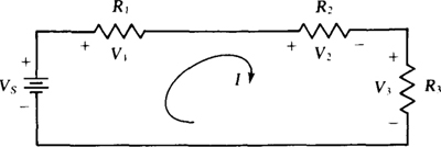
In the application of KVL, a loop current is usually referenced clockwise, as shown in the series circuit of Fig. 3-1, and KVL is applied in the direction of the current. (This is a series circuit because the same current I flows through all components.) The sum of the voltage drops across the resistors, V1 + V2 + V3, is set equal to the voltage rise Vs across the voltage source: V1 + V2 + V3 = Vs. Then the IR Ohm’s law relations are substituted for the resistor voltages:
Fig. 3-1

from which I = VS/RT and RT = R1 + R2 + R3. This RT is the total resistance of the series-connected resistors. Another term used is equivalent resistance, with symbol Req.
From this result it should be evident that, in general, the total resistance of series-connected resistors (series resistors) equals the sum of the individual resistances:

Further, if the resistances are the same (R), and if there are N of them, then RT = NR. Finding the current in a series circuit is easier using total resistance than applying KVL directly.
If a series circuit has more than one voltage source, then

in which each Vs term is positive for a voltage rise and is negative for a voltage drop in the direction of I.
KVL is seldom applied to a loop containing a current source because the voltage across the current source is not known and there is no formula for it.
The voltage division or voltage divider rule applies to resistors in series. It gives the voltage across any resistor in terms of the resistances and the total voltage across the series combination—the step of finding the resistor current is eliminated. The voltage division formula is easy to find from the circuit shown in Fig. 3-1. Consider finding the voltage V2. By Ohm’s law, V2 = IR2. Also, I = Vs/(R1 + R2 + R3). Eliminating I results in
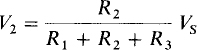
In general, for any number of series resistors with a total resistance of RT and with a voltage of Vs across the series combination, the voltage Vx across one of the resistors Rx is

This is the formula for the voltage division or divider rule. For this formula, Vs and Vx must have opposing polarities; that is, around a closed path one must be a voltage drop and the other a voltage rise. If both are rises or both are drops, the formula requires a negative sign. The voltage Vs need not be that of a source. It is just the total voltage across the series resistors.
Kirchhoff’s current law, abbreviated KCL, has three equivalent versions: At any instant in a circuit,
1. The algebraic sum of the currents leaving a closed surface is zero.
2. The algebraic sum of the currents entering a closed surface is zero.
3. The algebraic sum of the currents entering a closed surface equals the algebraic sum of those leaving.
The word “algebraic” means that the signs of the currents are included in the additions. Remember that a current entering is a negative current leaving, and that a current leaving is a negative current entering.
In almost all circuit applications, the closed surfaces of interest are those enclosing nodes. So, there is little loss of generality in using the word “node” in place of “closed surface” in each KCL version. Also, for a node to which no voltage sources are connected the most convenient KCL version is often the third one, restricted such that the currents entering are from current sources and the currents leaving are through resistors.
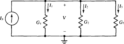
In the application of KCL, one node is selected as the ground or reference or datum node, which is often indicated by the ground symbol  Usually, the node at the bottom of the circuit is the ground node, as shown in the parallel circuit of Fig. 3-2. (This is a parallel circuit because the same voltage V is across all circuit components.) The voltages on other nodes are almost always referenced positive with respect to the ground node. At the nongrounded node in the circuit shown in Fig. 3-2, the sum of the currents leaving through resistors, I1 + I2 + I3, equals the current IS entering this node from the current source: I1 + I2 + I3 = IS. The substitution of the I = GV Ohm’s law relations for the resistor currents results in
Fig. 3-2

from which V = IS/GT and GT = G1 + G2 + G3 = 1/R1 + 1/R2 + 1/R3. This GT is the total conductance of the circuit. Another term used is equivalent conductance, with symbol Geq.
From this result it should be evident that, in general, the total conductance of parallel-connected resistors (parallel resistors) equals the sum of the individual conductances:

If the conductances are the same (G), and if there are N of them, then GT = NG and RT = 1/GT = 1/NG = R/N. Finding the voltage in a parallel circuit is easier using total conductance than applying KCL directly.
Sometimes working with resistances is preferable to conductances. Then from RT = 1/GT = 1/(G1+ G2 + G3+ …),
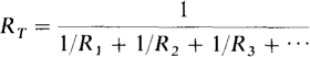
An important check on calculations with this formula is that RT must always be less than the least resistance of the parallel resistors.
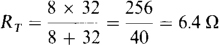
For the special case of just two parallel resistors,
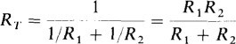
So, the total or equivalent resistance of two parallel resistors is the product of the resistances divided by the sum.
The symbol || as in R1 || R2 indicates the resistance of two parallel resistors: R1 || R2 = R1R2/(R1 + R2). It is also sometimes used to indicate that two resistors are in parallel.
If a parallel circuit has more than one current source,

in which each IS term is positive for a source current entering the nongrounded node and is negative for a source current leaving this node.
KCL is seldom applied to a node to which a voltage source is connected. The reason is that the current through a voltage source is not known and there is no formula for it.
The current division or current divider rule applies to resistors in parallel. It gives the current through any resistor in terms of the conductances and the current into the parallel combination—the step of finding the resistor voltage is eliminated. The current division formula is easy to derive from the circuit shown in Fig. 3-2. Consider finding the current I2. By Ohm’s law, I2 = G2V. Also, V = IS/(G1 + G2 + G3). Eliminating V results in
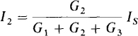
In general, for any number of parallel resistors with a total conductance GT and with a current IS entering the parallel combination, the current Ix through one of the resistors with conductance Gx is

This is the formula for the current division or divider rule. For this formula, IS and Ix must be referenced in the same direction, with Ix referenced away from the node of the parallel resistors that IS is referenced into. If both currents enter this node, then the formula requires a negative sign. The current IS need not be that of a source. It is just the total current entering the parallel resistors.
For the special case of two parallel resistors, the current division formula is usually expressed in resistances instead of conductances. If the two resistances are R1 and R2, the current I1 in the resistor with resistance R1 is
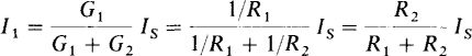
In general, as this formula indicates, the current flowing in one of two parallel resistors equals the resistance of the other resistor divided by the sum of the resistances, all times the current flowing into the parallel combination.
The basic equations V = RI, I = GV, P = VI, P = V2/R, and P = I2R are valid, of course, for the units of volts (V), amperes (a), ohms (Ω), siemens (S), and watts (W). But they are equally valid for the units of volts (V), milliamperes (mA), kilohms (kΩ), millisiemens (mS), and milliwatts (mW), the use of which is sometimes referred to as the kilohm-milliampere method. In this book, this second set will be used almost exclusively in the writing of network equations when the network resistances are in the kilohm range, because with it the writing of powers of 10 can be avoided.
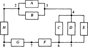
3.1 Determine the number of nodes and branches in the circuit shown in Fig. 3-3.
Fig. 3-3
Dots 1 and 2 are one node, as are dots 3 and 4 and also dots 5 and 6, all with connecting wires. Dot 7 and the two wires on both sides are another node, as are dot 8 and the two wires on both sides of it. So, there are five nodes. Each of the shown components A through H is a branch—eight branches in all.
3.2 Which components in Fig. 3-3 are in series and which are in parallel?
Components F, G, and H are in series because they carry the same current. Components A and B, being connected together at both ends, have the same voltage and so are in parallel. The same is true for components C, D, and E —they are in parallel. Further, the parallel group of A and B is in series with the parallel group of C, D, and E, and both groups are in series with components F, G, and H.
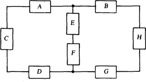
3.3 Identify all the loops and all the meshes for the circuit shown in Fig. 3-4. Also, specify which components are in series and which are in parallel.
Fig. 3-4
There are three loops: one of components A, E, F, D, and C; a second of components B, H, G, F, and E; and a third of A, B, H, G, D, and C. The first two loops are also meshes, but the third is not because components E and F are inside it. Components A, C, and D are in series because they carry the same current. For the same reason, components E and F are in series, as also are components B, H, and G. No components are in parallel.
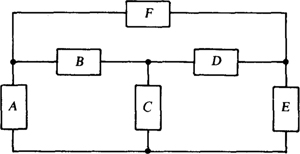
3.4 Repeat Prob. 3.3 for the circuit shown in Fig. 3-5.
Fig. 3-5
The three loops of components A, B, and C; C, D, and E; and F, D, and B are also meshes—the only meshes. All other loops are not meshes because components are inside them. Components A, B, D, and E form one of these other loops; components A, F, and E another one; components A, F, D, and C a third; and components F, E, C, and B a fourth. The circuit has three meshes and seven loops. No components are in series or in parallel.
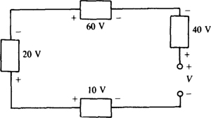
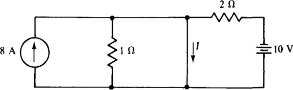
3.5 What is V across the open circuit in the circuit shown in Fig. 3-6?
Fig. 3-6
The sum of the voltage drops in a clockwise direction is, starting from the upper left corner,

In the summation, the 40 and 10 V are negative because they are voltage rises in a clockwise direction. The negative sign in the answer indicates that the actual open-circuit voltage has a polarity opposite the shown reference polarity.
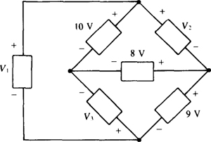
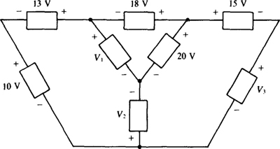
3.6 Find the unknown voltages in the circuit shown in Fig. 3-7. Find V1 first.
Fig. 3-7
The basic KVL approach is to use loops having only one unknown voltage apiece. Such a loop for V1 includes the 10-, 8-, and 9-V components. The sum of the voltage drops in a clockwise direction around this loop is

Similarly, for V2 the sum of the voltage drops clockwise around the top mesh is

Clockwise around the bottom mesh, the sum of the voltage drops is

The negative sign for V3 indicates that the polarity of the actual voltage is opposite the reference polarity.
3.7 What is the total resistance of 2-, 5-, 8-, 10-, and 17-Ω resistors connected in series?
The total resistance of series resistors is the sum of the individual resistances: RT = 2 + 5 + 8+ 10 + 17 = 42 Ω
3.8 What is the total resistance of thirty 6-Ω resistors connected in series?
The total resistance is the number of resistors times the common resistance of 6 Ω: RT, = 30 × 6 = 180 Ω
3.9 What is the total conductance of 4-, 10-, 16-, 20-, and 24-S resistors connected in series?
The best approach is to convert the conductances to resistances, add the resistances to get the total resistance, and then invert the total resistance to get the total conductance:

and
3.10 A string of Christmas tree lights consists of eight 6-W, 15-V bulbs connected in series. What current flows when the string is plugged into a 120-V outlet, and what is the hot resistance of each bulb?
The total power is PT = 8 × 6 = 48 W. From PT = VI, the current is I = PT/V = 48/120 = 0.4 A. And from P = I2R, the hot resistance of each bulb is R = P/I2 = 6/0.42 = 37.5 Ω
3.11 A 3-V, 300-mA flashlight bulb is to be used as the dial light in a 120-V radio. What is the resistance of the resistor that should be connected in series with the flashlight bulb to limit the current?
Since 3 V is to be across the flashlight bulb, there will be 120 – 3 = 117 V across the series resistor. The current is the rated 300 mA. Consequently, the resistance is 117/0.3 = 390Ω.
3.12 A person wants to move a 20-W FM-AM transistor radio from a junked car with a 6-V battery to a new car with a 12-V battery. What is the resistance of the resistor that should be connected in series with the radio to limit the current, and what is its minimum power rating?
From P = VI, the radio requires 20/6 = 3.33 A. The resistor, being in series, has the same current. Also, it has the same voltage because 12 – 6 = 6 V. As a result, R = 6/3.33 = 1.8Ω. With the same voltage and current, the resistor must dissipate the same power as the radio, and so has a 20-W minimum power rating.
3.13 A series circuit consists of a 240-V source and 12-, 20-, and 16-Q resistors. Find the current out of the positive terminal of the voltage source. Also find the resistor voltages. Assume associated references, as should always be done when there is no specification of references.
The current is the applied voltage divided by the equivalent resistance:
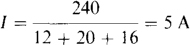
Each resistor voltage is this current times the corresponding resistance: V12 = 5 × 12 = 60 V, V20 = 5 × 20 = 100 V, and V16 = 5 × 16 = 80 V. As a check, the sum of the resistor voltages is 60 + 100 + 80 = 240 V, the same as the applied voltage.
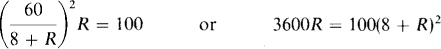
3.14 A resistor in series with an 8-Q resistor absorbs 100 W when the two are connected across a 60-V line. Find the unknown resistance R.
The total resistance is 8 + R, and thus the current is 60/(8 + R). From I2R = P,
which simplifies to R2 – 20R + 64 = 0. The quadratic formula can be used to find R. Recall that for the equation ax2 + bx + c – 0, this formula is
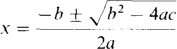
so
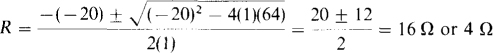
A resistor with a resistance of either 16 or 4 Ω will dissipate 100 W when connected in series with an 8-Ω resistor across a 60-V line.
This particular quadratic equation can be factored without using the quadratic formula. By inspection, R2 – 20R + 64 = (R – 16)(R – 4) = 0, from which R = 16 Ω or R = 4 Ω, the same as before.
3.15 Resistors R1, R2, and R3 are in series with a 100-V source. The total voltage drop across R1 and R2 is 50 V, and that across R2 and R3 is 80 V. Find the three resistances if the total resistance is 50 Ω.
The current is the applied voltage divided by the total resistance: I = 100/50 = 2 A. Since the voltage across resistors R1 and R2 is 50 V, there must be 100 – 50 = 50 V across R3. By Ohm’S law, R3 = 50/2 = 25 Ω. Resistors R2 and R3 have 80 V across them, leaving 100 – 80 = 20 V across R1. Thus, R1 20/2 = 10 Ω. The resistance of R2 is the total resistance minus the resistances of R1 and R3: R2 = 50 – 10 – 25 = 15 Ω.
3.16 What is the maximum voltage that can be applied across the series combination of a 150-Ω, 2-W resistor and a 100-Ω, 1-W resistor without exceeding the power rating of either resistor?
From P = I2R, the maximum safe current for the 150-Q resistor is 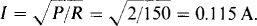 That for the 100-Ω resistor is
  The maximum current cannot exceed the lesser of these two currents and so is 0.1 A. For this current, V = I (R1 + R2) = 0.1(150 + 100) = 25 V.
3.17 In a series circuit, a current flows from the positive terminal of a 180-V source through two resistors, one of which has 30 Ω of resistance and the other of which has 45 V across it. Find the current and the unknown resistance.
The 30-Ω resistor has 180 – 45 = 135 V across it and thus a 135/30 = 4.5-A current through it. The other resistance is 45/4.5 = 10 Ω.
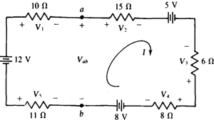
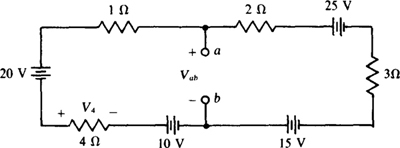
3.18 Find the current and unknown voltages in the circuit shown in Fig. 3-8.
Fig. 3-8
The total resistance is the sum of the resistances: 10 + 15 + 6 + 8 + 11 = 50 Ω. The total voltage rise from the voltage sources in the direction of I is 12 — 5 + 8 = 15 V. The current I is this voltage divided by the total resistance: I = 15/50 = 0.3 A. By Ohm’S law, V1, = 0.3 × 10 = 3 V, V2 = 0.3 × 15 = 4.5 V, V3 = – 0.3 × 6 = – 1.8 V, V4 = 0.3 × 8 = 2.4 V, and V5 = –0.3 × 11 = –3.3 V. The equations for V3, and V5 have negative signs because the references for these voltages and the reference for I are not associated.
3.19 Find the voltage Vab in the circuit shown in Fig. 3-8.
Vab is the voltage drop from node a to node b, which is the sum of the voltage drops across the components connected between nodes a and b either to the right or to the left of node a. It is convenient to choose the path to the right because this is the direction of the I = 0.3-A current found in the solution of Prob. 3.18. Thus,

Note that an IR drop is always positive in the direction of I. A voltage reference, and that of V3, in particular here, has no effect on this.
3.20 Find I1 I2, and V in the circuit shown in Fig. 3-9.
Fig. 3-9
Since the 90-V source is across the 10-Ω resistor, I1, = 90/10 = 9 A. Around the outside loop in a clockwise direction, the voltage drop across the two resistors is (25 + 15)I2 = 40I2. This is equal to the sum of the voltage rises across the voltage sources in this outside loop:

The voltage V is equal to the sum of the drops across the 25-Ω resistor and the 30-V source: V = (1.5 × 25) + 30 = 67.5 V. Notice that the parallel 10-Ω resistor does not affect I2. In general, resistors in parallel with voltage sources that have zero internal resistances (ideal voltage sources) do not affect currents or voltages elsewhere in a circuit. They do, however, cause an increase in current flow in these voltage sources.
3.21 A 90-V source is in series with five resistors having resistances of 4, 5, 6, 7, and 8 Ω. Find the voltage across the 6-Ω resistor. (Here “voltage” refers to the positive voltage, as it will in later problems unless otherwise indicated. The same is true for current.)
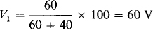
By the voltage division formula, the voltage across a resistor in a series circuit equals the resistance of that resistor times the applied voltage divided by the total resistance. So,
3.22 Use voltage division to determine the voltages V4 and V5 in the circuit shown in Fig. 3-8.
The total voltage applied across the resistors equals the sum of the voltage rises from the voltage sources, preferably in a clockwise direction: 12 — 5 + 8 = 15 V. The polarity of this net voltage is such that it produces a clockwise current flow. In this sum the 5 V is negative because it is a drop, and rises are being added. Put another way, the polarity of the 5-V source opposes the polarities of the 12- and 8-V sources. The V4 voltage division formula should have a positive sign because V4 is a drop in the clockwise direction—it opposes the polarity of the net applied voltage:
The voltage division formula for V5 requires a negative sign because both V5 and the net source voltage are rises in the clockwise direction:
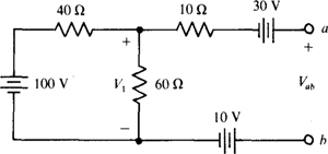
3.23 Find the voltage Vab across the open circuit in the circuit shown in Fig. 3-10.
Fig. 3-10
The 10-Ω resistor has zero current flowing through it because it is in series with an open circuit. (Also, it has zero volts across it.) Consequently, voltage division can be used to obtain V1. The result is
Then, a summation of voltage drops around the right-hand half of the circuit gives 0 – 30 + Vab + 10 – 60 = 0. Therefore, Vab = 80 V.
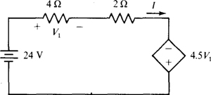
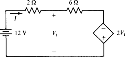
3.24 For the circuit of Fig. 3-11, calculate I and the power absorbed by the dependent source.
Fig. 3-11
A good first step is to solve for the controlling quantity V1 in terms of I. Applying Ohm’S law to the 4-Ω resistor gives V1 = 41. Consequently, in the direction of I, the voltage rise across the dependent source is 4.5(4I) = 18I. Then by KVL,

The negative sign indicates that the 2-A current flows counterclockwise, opposite the reference direction for I.
Since the current and voltage references for the dependent source are not associated, the power absorbed formula has a negative sign:

But I = –2 A, and so P = –18(– 2)2 = – 72 W. The presence of the negative sign means that the dependent source is supplying power instead of absorbing it.
3.25 In the circuit of Fig. 3-11, determine the resistance “seen” by the independent voltage source.
The resistance “seen” by the source is equal to the ratio of the source voltage to the current that flows out of the positive terminal of the source:
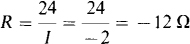
The negative sign of the resistance is a result of the action of the dependent source. It indicates that the remainder of the circuit supplies power to the independent source. Actually, it is the dependent source alone that supplies this power, as well as the power to the two resistors.
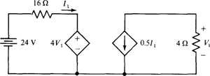
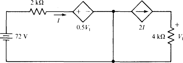
3.26 Find V1 in the circuit of Fig. 3-12.
Fig. 3-12
First observe that no current flows in the single wire connecting the two halves of this circuit, as is evident from enclosing either half in a closed surface. Then only this single wire would cross this surface, and since the sum of the currents leaving any closed surface must be zero, the current in this wire must be zero. From another point of view, there is no return path for a current that would flow in this wire.
From KVL applied to the left-hand half of the circuit, 16I1 + 4V1 = 24. And for the right-hand half of the circuit, Ohm’S law gives

Then, substituting for I1, in the KVL equation produces

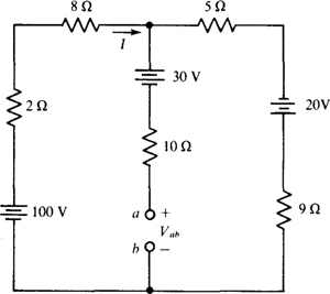
3.27 Calculate I and Vab in the circuit of Fig. 3-13.
Fig. 3-13
Because of the open circuit between nodes a and b, the middle branch has no effect on the current I. Consequently, I can be obtained by applying KVL to the outside loop. The total resistance of this loop is 2 + 8 + 5 + 9 = 24 Ω. And in the direction of I, the sum of the voltage rises from voltage sources is 100 + 20= 120 V. So, I = 120/24 = 5 A.
From the summing of voltage drops across the right-hand branch, the voltage drop, top to bottom, across the middle branch is 5(5) – 20 + 5(9) = 50 V. Consequently, VBb – 50 – 30 = 20 V because there is zero volts across the 10-Ω resistor.
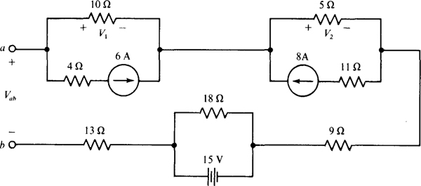
3.28 Determine the voltage drop Vab across the open circuit in the circuit of Fig. 3-14.
Fig. 3-14
Because of the open circuit, no current flows in the 9-Ω and 13-Ω resistors and so there is zero volts across each of them. Also, then, all the 6-Ω source current flows through the 10-Ω resistor and all the 8-A source current flows through the 5-Ω resistor, making V1 = – 6(10) = – 60 V and V2 spectively. So, Vab, the voltage drop from node a to b, is from summing voltage drops,

The 4-, 11-, 9-, 18-, and 13-Ω resistors have no effect on this result.
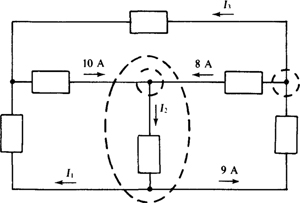
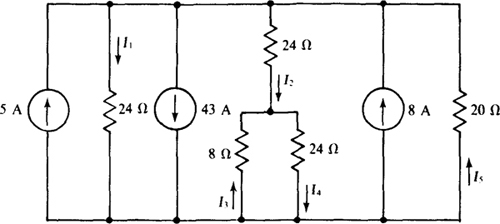
3.29 Find the unknown currents in the circuit shown in Fig. 3-15. Find I1, first.
Fig. 3-15
The basic KCL approach is to find closed surfaces such that only one unknown current flows across each surface. In Fig. 3-15, the large dashed loop represents a closed surface drawn such that I1 is the only unknown current flowing across it. Other currents flowing across it are the 10-, 8-, and 9-A currents. I1 and the 9-A currents leave this closed surface, and the 8-A and 10-A currents enter it. By KCL, the sum of the currents leaving is zero: I1 + 9 – 8 – 10 = 0, or I1, = 9 A. I2 is readily found from summing the currents leaving the middle top node: I2 – 8 – 10 = 0, or I2 = 18 A. Similarly, at the right top node, I3 + 8 – 9 = 0, and I3 = 1 A. Checking at the left top node: 10 – I1 – I3 = 10 – 9 – 1 = 0, as it should be.
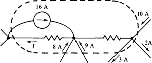
3.30 Find I for the circuit shown in Fig. 3-16.
Fig. 3-16
Since I is the only unknown current flowing across the shown dashed loop, it can be found by setting to zero the sum of the currents leaving this loop: I – 16 – 8 – 9 + 3 + 2 – 10 = 0, from which I = 38 A.
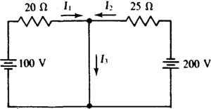
3.31 Find the short-circuit current I3 for the circuit shown in Fig. 3-17.
Fig. 3-17
The short circuit places the 100 V of the left-hand voltage source across the 20-Ω resistor, and it places the 200 V of the right-hand source across the 25-Ω resistor. By Ohm’S law, I1 = 100/20 = 5 A and I2 = –200/25 = –8 A. The negative sign occurs in the I2 formula because of nonassociated references.
From KCL applied at the top middle node, I3 = I1 + I2 = 5 – 8 = —3 A. Of course the negative sign in the answer means that 3 A actually flows up through the short circuit, opposite the direction of the I3 current reference arrow.
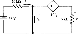
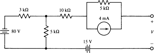
3.32 Calculate V in the circuit of Fig. 3-18.
Fig. 3-18
The short circuit places all 36 V of the voltage source across the 20-kΩ resistor. So, by Ohm’S law, I1 = 36/20 = 1.8 mA. (The kilohm-milliampere method was used in finding I1.) Applying KCL to the top middle node gives

Finally, by Ohm’s law,

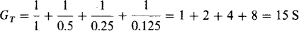
3.33 Find the total conductance and resistance of four parallel resistors having resistances of 1, 0.5, 0.25, and 0.125 Ω.
The total conductance is the sum of the individual conductances:
The total resistance is the inverse of this total conductance: RT = 1/GT = 1/15 = 0.0667 Ω
3.34 Find the total resistance of fifty 200-Ω resistors connected in parallel.
The total resistance equals the common resistance divided by the number of resistors: 200/50 = 4 Ω.
3.35 A resistor is to be connected in parallel with a 10-kΩ resistor and a 20-kΩ resistor to produce a total resistance of 12 kΩ. What is the resistance of the resistor?
Assuming that the added resistor is a conventional resistor, no added parallel resistor will give a total resistance of 12 kΩ because the total resistance of parallel resistors is always less than the least individual resistance, which is 10 kΩ. With transistors, however, it is possible to make a component that has a negative resistance and that in parallel can cause an increase in total resistance. Generally, however, the term resistor means a conventional resistor that has only positive resistance.
3.36 Three parallel resistors have a total conductance of 1.75 S. If two of the resistances are 1 and 2 Ω, what is the third resistance?
The sum of the individual conductances equals the total conductance:

The resistance of the third resistor is the inverse of this conductance: R3 = 1/G3 = 1/0.25 = 4 Ω.
3.37 Without using conductances, find the total resistance of two parallel resistors having resistances of 5 and 20 Ω.
The total resistance equals the product of the individual resistances divided by the sum: RT = (5 × 20)/(5 + 20) = 100/25 = 4 Ω.
3.38 Repeat Prob. 3.37 for three parallel resistors having resistances of 12, 24, and 32 Ω.
One approach is to consider the resistances two at a time. For the 12- and the 24-Ω resistances, the equivalent resistance is
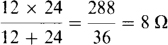
This combined with the 32-Ω resistance gives a total resistance of
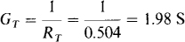
3.39 A 60-W, a 100-W, and a 200-W light bulb are connected in parallel across a 120-V line. Obtain the equivalent hot resistance of this combination from the individual hot resistances of the bulbs.
From R = V2/P, the individual resistances are 1202/60 = 240 Ω, 1202, 100 = 144 Ω, and 1202/200 = 72 Ω. The 72- and 144-Ω resistances have an equivalent resistance of (72 × 144)/(72 + 144) = 48 Ω. The equivalent resistance of this and the 240-Ω resistance is the total equivalent hot resistance: (240 × 48)/(240 × 48) = 40 Ω. As a check, from the total power of 360 W, RT, = V2/P = 1202/360 = 40 Ω.
3.40 Determine RT, in RT, = (4 + 24|| 12)||6.
It is essential to start evaluating inside the parentheses, and then work out. By definition, the term 24 || 12 = (24 × 12)/(24 + 12) = 8. This adds to the 4: 4 + 8 = 12. The expression reduces to 12||6, which is (12 × 6)/(12 + 6) = 4. Thus, RT = 4 Ω.
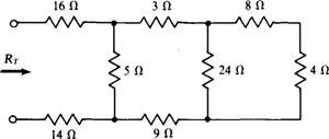
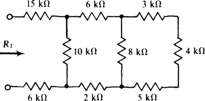
3.41 Find the total resistance RT of the resistor ladder network shown in Fig. 3-19.
Fig. 3-19
To find the equivalent resistance of a ladder network by combining resistances, always start at the end opposite the input terminals. At this end, the series 4- and 8-Ω resistors have an equivalent resistance of 12 Ω. This combines in parallel with the 24-Ω resistance: (24 × 12)/(24 + 12) = 8 Ω. This adds to the 3 and the 9 Ω of the series resistors for a sum of 8 + 3 + 9 = 20 Ω. This combines in parallel with the 5-Ω resistance: (20 × 5)/(20 + 5) = 4 Ω. RT, is the sum of this resistance and the resistances of the series 16- and 14-Ω resistors: RT = 4 + 16 + 14 = 34 Ω.
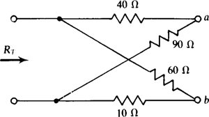
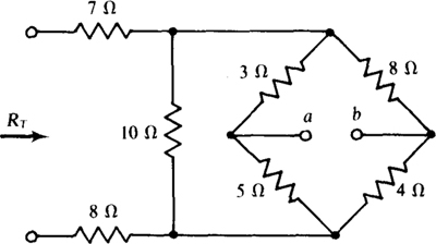
3.42 In the circuit shown in Fig. 3-20 find the total resistance RT with terminals a and b (a) open-circuited, and (b) short-circuited.
Fig. 3-20
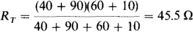
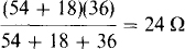
(a) With terminals a and b open, the 40- and 90-Ω resistors are in series, as are the 60- and 10-Ω resistors. The two series combinations are in parallel; so
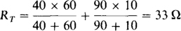
(b) For terminals a and b short-circuited, the 40- and 60-Ω resistors are in parallel, as are the 90- and 10-Ω resistors. The two parallel combinations are in series, making
3.43 A 90-A current flows into four parallel resistors having resistances of 5, 6, 12, and 20 Ω. Find the current in each resistor.
The total resistance is
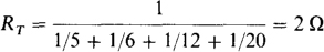
This value times the current gives the voltage across the parallel combination: 2 × 90 = 180 V. Then by Ohm’s law, I5 = 180/5 = 36 A, I6 = 180/6 = 30 A, I12 = 180/12 = 15 A, and I20 = 180/20 = 9 A.
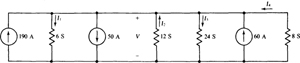
3.44 Find the voltage and unknown currents in the circuit shown in Fig. 3-21.
Fig. 3-21
Even though it has several dots, the top line is just a single node because the entire line is at the same potential. The same is true of the bottom line. Thus, there are just two nodes and one voltage V. The total conductance of the parallel-connected resistors is G = 6 + 12 + 24 + 8 = 50 S. Also, the total current entering the top node from current sources is 190 – 50 + 60 = 200 A. This conductance and current can be used in the conductance version of Ohm’S law, I = GV, to obtain the voltage: V= I/G – 200/50 = 4 V. Since this is the voltage across each resistor, the resistor currents are I1 = 6 × 4 = 24 A, I2 = – 12 × 4 = – 48 A, I3 = 24 × 4 = 96 A, and I4 = –8 × 4 = –32 A. The negative signs are the result of non-associated references. Of course, all the actual resistor currents leave the top node.
Note that the parallel current sources have the same effect as a single current source, the current of which is the algebraic sum of the individual currents from the sources.
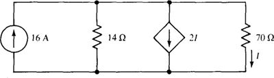
3.45 Use current division to find the currents I2 and I3 in the circuit shown in Fig. 3-21.
The sum of the currents from current sources into the top node is 190 – 50 + 60 = 200 A. Also, the sum of the conductances is 6 + 12 + 24 + 8 = 50 S. By the current division formula,

The formula for I2 has a negative sign because I2 has a reference into the top node, and the sum of the currents from current sources is also into the top node. For a positive sign, one current in the formula must be into a node and the other current must be out of the same node.
3.46 A 90-A current flows into two parallel resistors having resistances of 12 and 24 Ω. Find the current in the 24-Ω resistor.
The current in the 24-Ω resistor equals the resistance of the other parallel resistor divided by the sum of the resistances, all times the input current:
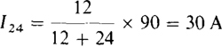
As a check, this current results in a voltage of 30 × 24 = 720 V, which is also across the 12-Ω resistor. Thus, I12 = 720/12 = 60 A, and I24 + I12 = 30 + 60 = 90 A, which is the input current.
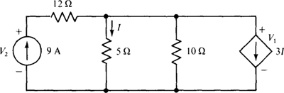
3.47 Calculate V1 and V2 in the circuit of Fig. 3-22.
Fig. 3-22
A good first step is to solve for the controlling current I in terms of V1: I = V1/5. Thus, the dependent source current is, in terms of V1, 3(V1,/5) = 0.6V1, directed downward. Then, KCL applied at the top right-hand node gives
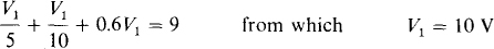
The voltage drop across the 12-Ω resistor is 9(12) = 108 V. Finally, KVL applied around the outside loop results in V2 = 108 + 10 = 118 V. Observe that the 12-Ω resistor has no effect on V1, but it does have an effect on V2,
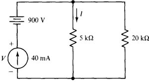
3.48 Calculate I and V in the circuit of Fig. 3-23.
Fig. 3-23
The source current of 40 mA flows into the parallel resistors. So, by current division,
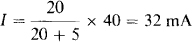
Then by KVL, V = –900 + 32(5) = –740 V. Observe that although the voltage-source voltage has an effect on the current-source voltage, it has no effect on the resistor current I.
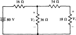
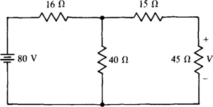
3.49 Use voltage division twice to find V1 in the circuit shown in Fig. 3-24.
Fig. 3-24
Clearly, V1 can be found from V2 by voltage division. And V2 can be found from the source voltage by voltage division used with the equivalent resistance to the right of the 16-Ω resistor. This resistance is
By voltage division,

A common error in finding V2 is to neglect the loading of the resistors to the right of the V2 node.
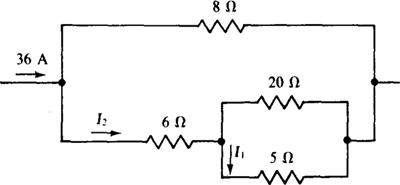
3.50 Use current division twice to find I1 in the circuit shown in Fig. 3-25.
Fig. 3-25
Obviously I1 can be found from I2 by current division. And, if the total resistance of the bottom three branches is found, current division can be used to find I2 from the input current. The needed total resistance is
By the two-resistance form of the current division formula,

3.51 Determine the number of nodes, branches, loops, and meshes in the circuit shown in Fig. 3-26.
Fig. 3-26
Ans. 6 nodes, 8 branches, 7 loops, 3 meshes
3.52 Find V1, V2, and V3 for the circuit shown in Fig. 3-26.
Ans. V1 = 26V, V2 = –21 V, V3 = 2 V
3.53 Four resistors in series have a total resistance of 500 Ω. If three of the resistors have resistances of 100, 150, and 200 Ω, what is the resistance of the fourth resistor?
Ans. 50 Ω
3.54 Find the total conductance of 2-, 4-, 8-, and 10-S resistors connected in series.
Ans. 1.03 S
3.55 A 60-W, 120-V light bulb is to be connected in series with a resistor across a 277-V line. What is the resistance and minimum power rating of the resistor required if the light bulb is to operate under rated conditions?
Ans. 314 Ω, 78.5 W
3.56 A series circuit consists of a dc voltage source and 4-, 5-, and 6-Ω resistors. If the current is 7 A, find the source voltage.
Ans. 105 V
3.57 A 12-V battery with a 0.3-Ω internal resistance is to be charged from a 15-V source. If the charging current should not exceed 2 A, what is the minimum resistance of a series resistor that will limit the current to this safe value?
Ans. 1.2 Ω
3.58 A resistor in series with a 100-Ω resistor absorbs 80 W when the two are connected across a 240-V line. Find the unknown resistance.
Ans. 20 or 500 Ω
3.59 A series circuit consists of a 4-V source and 2-, 4-, and 6-Ω resistors. What is the minimum power rating of each resistor if the resistors are available in power ratings of  W, 1 W, and 2 W?
Ans. P2 = W, P4 = W, P6 = 1 W
3.60 Find Vab in the circuit shown in Fig. 3-27.
Fig. 3-27
Ans. 20 V
3.61 Use voltage division to find the voltage V4 in the circuit shown in Fig. 3-27.
Ans. –8 V
3.62 A series circuit consists of a 100-V source and 4-, 5-, 6-, 7-, and 8-Ω resistors. Use voltage division to determine the voltage across the 6-Ω resistor.
Ans. 20 V
3.63 Determine I in the circuit of Fig. 3-28.
Fig. 3-28
Ans. 3 A
3.64 Find V across the open circuit in the circuit of Fig. 3-29.
Fig. 3-29
Ans. –45 V
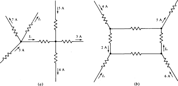
3.65 Find the indicated unknown currents in the circuits shown in Fig. 3-30.
Fig. 3-30
Ans. I1 = 2A, I2 = –6A, I3 = –5A, I4 = 3 A
3.66 Find the short-circuit current I in the circuit shown in Fig. 3-31.
Fig. 3-31
Ans. 3 A
3.67 Calculate V1 in the circuit of Fig. 3-32.
Fig. 3-32
Ans. 96 V
3.68 What are the different resistances that can be obtained with three 4-Ω resistors?
Ans. 1.33, 2, 2.67, 4, 6, 8, and 12 Ω
3.69 A 100-Ω resistor and another resistor in parallel have an equivalent resistance of 75 Ω. What is the resistance of the other resistor?
Ans. 300 Ω
3.70 Find the equivalent resistance of four parallel resistors having resistances of 2, 4, 6, and 8 Ω.
Ans. 0.96 Ω
3.71 Three parallel resistors have a total conductance of 2 mS. If two of the resistances are 1 and 5 kΩ, what is the third resistance?
Ans. 1.25 kΩ
3.72 The equivalent resistance of three parallel resistors is 10 Ω. If two of the resistors have resistances of 40 and 60 Ω, what is the resistance of the third resistor?
Ans. 17.1 Ω
3.73 Determine RT in RT = (24||48 + 24) || 10.
Ans. 8 Ω
3.74 Determine RT in RT = (6|| 12 + 10||40) || (6 + 2).
Ans. 4.8 Ω
3.75 Find the total resistance RT of the resistor ladder network shown in Fig. 3-33.
Fig. 3-33
Ans. 26.6 kΩ
3.76 Repeat Prob. 3.75 with all resistances doubled.
Ans. 53.2 kΩ
3.77 In the circuit shown in Fig. 3-34, find RT with terminals a and b (a) open-circuited, and (b) short-circuited.
Fig. 3-34
Ans. (a) 18.2 Ω, (b) 18.1 Ω
3.78 A 15-mA current flows into four parallel resistors having resistances of 4, 6, 8, and 12 kΩ. Find each resistor current.
Ans. I4 = 6mA, I6 = 4 m A, I8 = 3 m A, I12 = 2 m A
3.79 Repeat Prob. 3.78 with all resistances doubled.
Ans. Same currents
3.80 Find the unknown currents in the circuit shown in Fig. 3-35.
Fig. 3-35
Ans. I1 = –10A, I2 = –8A, I3 = 6sA, I4 = –2A, I5 = 12A
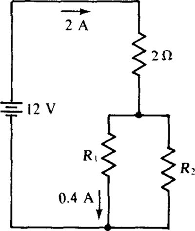
3.81 Find R1 and R2 for the circuit shown in Fig. 3-36.
Fig. 3-36
Ans. R1 = 20Ω, R2 = 5Ω
3.82 In the circuit shown in Fig. 3-36, let R1, = 6 Ω and R2 = 12 Ω. Then use current division to find the new current in the R1 resistor.
Ans. 1.33 A
3.83 A 60-A current flows into a resistor network described by RT = 40||(12 + 40||10). Find the current in the 10-Ω resistor.
Ans. 32 A
3.84 A 620-V source connected to a resistor network described by RT = 50 + R||20 provides 120 V to the 20-Ω resistor. What is R?
Ans. 30 Q
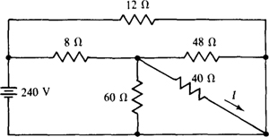
3.85 Find I in the circuit shown in Fig. 3-37.
Fig. 3-37
Ans. 4 A
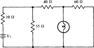
3.86 In the circuit shown in Fig. 3-38 there is a 120-V, 60-W light bulb. What must be the supply voltage Vs for the light bulb to operate under rated conditions?
Fig. 3-38
Ans. 285 V
3.87 In the circuit of Fig. 3-39, calculate I and also the power absorbed by the dependent source.
Fig. 3-39
Ans. 2 A, 560 W
3.88 Use voltage division twice to find the voltage V in the circuit shown in Fig. 3-40.
Fig. 3-40
Ans. 36 V
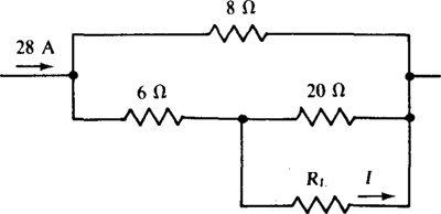
3.89 In the circuit shown in Fig. 3-41, use current division twice to calculate the current I in the RL for (a) RL = 0Ω, (b) RL = 5Ω, and (c) RL = 20 Ω.
Fig. 3-41
Ans. (a) 16 A, (b) 9.96 A, (c) 4.67 A
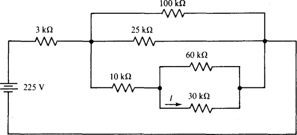
3.90 Use repeated current division in finding I in the circuit of Fig. 3-42.
Fig. 3-42
Ans. 4 mA