Network theorems are often important aids for network analyses. Some theorems apply only to linear, bilateral circuits, or portions of them. A linear electric circuit is constructed of linear electric elements as well as of independent sources. A linear electric element has an excitation-response relation such that doubling the excitation doubles the response, tripling the excitation triples the response, and so on. A bilateral circuit is constructed of bilateral elements as well as of independent sources. A bilateral element operates the same upon reversal of the excitation, except that the response also reverses. Resistors are both linear and bilateral if they have voltage-current relations that obey Ohm’s law. On the other hand, a diode, which is a common electronic component, is neither linear nor bilateral.
Some theorems require deactivation of independent sources. The term deactivation refers to replacing all independent sources by their internal resistances. In other words, all ideal voltage sources are replaced by short circuits, and all ideal current sources by open circuits. Internal resistances are not affected, nor are dependent sources. Dependent sources are never deactivated in the application of any theorem.
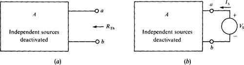
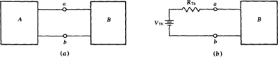
Thévenin’s and Norton’s theorems are probably the most important network theorems. For the application of either of them, a network is divided into two parts, A and B, as shown in Fig. 5-la, with two joining wires. One part must be linear and bilateral, but the other part can be anything.
Thévenin’s theorem specifies that the linear, bilateral part, say part A, can be replaced by a Thévenin equivalent circuit consisting of a voltage source and a resistor in series, as shown in Fig. 5-1b, without any changes in voltages or currents in part B. The voltage VTh of the voltage source is called the Thévenin voltage, and the resistance RTh of the resistor is called the Thévenin resistance.
As should be apparent from Fig. 5-lb, VTh is the voltage across terminals a and b if part B is replaced by an open circuit. So, if the wires are cut at terminals a and b in either circuit shown in Fig. 5-1, and if a voltmeter is connected to measure the voltage across these terminals, the voltmeter reading is VTh. This voltage is almost always different from the voltage across terminals a and b with part B connected. The Thévenin or open-circuit voltage Vn is sometimes designated by Voc.
Fig. 5-1
With the joining wires cut, as shown in Fig. 5-2a, RTh is the resistance of part A with all independent sources deactivated. In other words, if all independent sources in part A are replaced by their internal resistances, an ohmmeter connected to terminals a and b reads Thévenin’s resistance.
Fig. 5-2
If in Fig. 5-2a the resistors in part A are in a parallel-series configuration, then RTh can be obtained readily by combining resistances. If, however, part A contains dependent sources (remember, they are not deactivated), then, of course, resistance combination is not applicable. But in this case the approach shown in Fig. 5-2b can be used. An independent source is applied, either voltage or current and of any value, and RTh obtained from the resistance “seen” by this source. Mathematically,

So, if a source of voltage Vs is applied, then Is is calculated for this ratio. And if a source of current Is is applied, then Vs is calculated. The preferred source, if any, depends on the configuration of part A.
Thévenin’s theorem guarantees only that the voltages and currents in part B do not change when part A is replaced by its Thévenin equivalent circuit. The voltages and currents in the Thévenin circuit itself are almost always different from those in the original part A, except at terminals a and b where they are the same, of course.
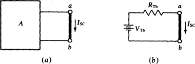
Although RTh is often determined by finding the resistance at terminals a and b with the connecting wires cut and the independent sources deactivated, it can also be found from the current Isc that flows in a short circuit placed across terminals a and b, as shown in Fig. 5-3a. As is apparent from Fig. 5-3b, this short-circuit current from terminal a to b is related to the Thévenin voltage and resistance. Specifically,
Fig. 5-3

So, RTh is equal to the ratio of the open-circuit voltage at terminals a and b and the short-circuit current between them. With this approach to determining RTh, no sources are deactivated.
From VTh = IscRTh, it is evident that the Thévenin equivalent can be obtained by determining any two of the quantities VTh, Isc, and RTh. Common sense dictates that the two used should be the two that are the easiest to determine.
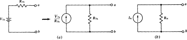
The Norton equivalent circuit can be derived by applying a source transformation to the Thévenin equivalent circuit, as illustrated in Fig. 5-4a. The Norton equivalent circuit is sometimes illustrated as in Fig. 5-4b, in which IN = VTh/RTh and RN = RTh. Notice that, if a short circuit is placed across terminals a and b in the circuit shown in Fig. 5-4b, the short-circuit current Isc from terminal a to b is
Fig. 5-4
equal to the Norton current IN. Often in circuit diagrams, the notation ISC is used for the source current instead of IN. Also, often RTh is used for the resistance instead of RN.
In electronic circuit literature, an electronic circuit with a load is often described as having an output resistance Rout. If the load is disconnected and if the source at the input of the electronic circuit is replaced by its internal resistance, then the output resistance Rout of the electronic circuit is the resistance “looking in” at the load terminals. Clearly, it is the same as the Thévenin resistance.
An electronic circuit also has an input resistance Rin, which is the resistance that appears at the input of the circuit. In other words, it is the resistance “seen” by the source. Since an electronic circuit typically contains the equivalent of dependent sources, the input resistance is determined in the same way that a Thévenin resistance is often obtained—by applying a source and determining the ratio of the source voltage to the source current.
The maximum power transfer theorem specifies that a resistive load receives maximum power from a linear, bilateral dc circuit if the load resistance equals the Thévenin resistance of the circuit as “seen” by the load. The proof is based on calculus. Selecting the load resistance to be equal to the circuit Thévenin resistance is called matching the resistances. With matching, the load voltage is KTh/2, and so the power consumed by the load is (VTh/2)2 / RTh = V2Th/4RTh.
The superposition theorem specifies that, in a linear circuit containing several independent sources, the current or voltage of a circuit element equals the algebraic sum of the component voltages or currents produced by the independent sources acting alone. Put another way, the voltage or current contribution from each independent source can be found separately, and then all the contributions algebraically added to obtain the actual voltage or current with all independent sources in the circuit.
This theorem applies only to independent sources—not to dependent ones. Also, it applies only to finding voltages and currents. In particular, it cannot be used to find power in dc circuits. Additionally, the theorem applies to each independent source acting alone, which means that the other independent sources must be deactivated. In practice, though, it is not essential that the independent sources be considered one at a time; any number can be considered simultaneously.
Because applying the superposition theorem requires several analyses, more work may be done than with a single mesh, loop, or nodal analysis with all sources present. So, using the superposition theorem in a dc analysis is seldom advantageous. It can be useful, though, in the analyses of some of the operational-amplifier circuits of the next chapter.
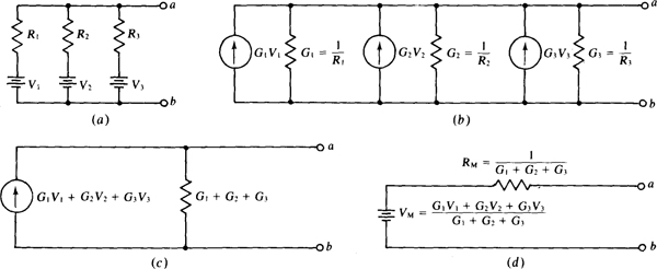
Millman’s theorem is a method for reducing a circuit by combining parallel voltage sources into a single voltage source. It is just a special case of the application of Thévenin’s theorem.
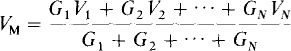
Figure 5-5 illustrates the theorem for only three parallel voltage sources, but the theorem applies to any number of such sources. The derivation of Millman’s theorem is simple. If the voltage sources shown in Fig. 5-5a are transformed to current sources (Fig. 5-5b) and the currents added, and if the conductances are added, the result is a single current source of G1V1 + G2 V2 + G3V3 in parallel with a resistor having a conductance of G1 + G2 + G3 (Fig. 5-5c). Then, the transformation of this current source to a voltage source gives the final result indicated in Fig. 5-5d. In general, for N parallel voltage sources the Millman voltage source has a voltage of
Fig. 5-5
and the Millman series resistor has a resistance of
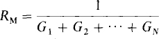
Note from the voltage source formula that, if all the sources have the same voltage, this voltage is also the Millman source voltage.
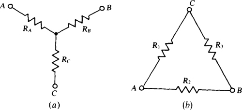
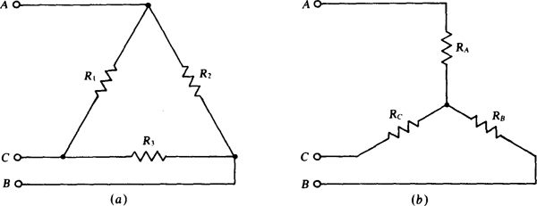
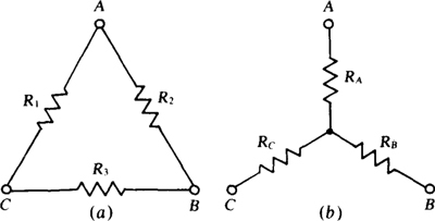
Figure 5-6a shows a Y (wye) resistor circuit and Fig. 5-6b a Δ (delta) resistor circuit. There are other names. If the Y circuit is drawn in the shape of a T, it is also called a T (tee) circuit. And if the Δ circuit is drawn in the shape of a π, it is also called a π (pi) circuit.
Fig. 5-6
It is possible to transform a Y to an equivalent Δ and also a Δ to an equivalent Y. The corresponding circuits are equivalent only for voltages and currents external to the Y and Δ circuits. Internally, the voltages and currents are different.
Transformation formulas can be found from equating resistances between two lines to a Δ and a Y when the third line to each is open. This equating is done three times, with a different line open each time. Some algebraic manipulation of the results produces the following Δ-to-Y transformation formulas:

Also produced are the following Y-to-Δ transformation formulas:

Notice in the Δ-to-Y transformation formulas that the denominators are the same: R1 + R2 + R3, the sum of the A resistances. In the Y-to-Δ transformation formulas, the numerators are the same: RARB + RARC + RBRC the sum of the different products of the Y resistances taken two at a time.
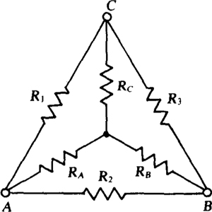
Drawing the Y inside the Δ, as in Fig. 5-7, is a good aid for remembering the numerators of the Δ-to-Y transformation formulas and the denominators of the Y-to-Δ transformation formulas. For each Y resistor in the Δ-to-Y transformation formulas, the two resistances in each numerator product are those of the two Δ resistors adjacent to the Y resistor being found. In the Y-to-Δ transformation formulas, the single Y resistance in each denominator is that of the Y resistor opposite the Δ resistor being found.
If it happens that each Y resistor has the same value RY, then each resistance of the corresponding Δ is 3RY, as the formulas give. And if each Δ resistance is RΔ, then each resistance of the corresponding Y is RΔ/3. So, in this special but fairly common case, RΔ = 3RY and, of course, RY = RΔ/3.
Fig. 5-7
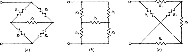
As illustrated in Fig. 5-8a, a bridge resistor circuit has two joined Δ’s or, depending on the point of view, two joined Y’s with a shared branch. Although the circuit usually appears in this form, the forms shown in Fig. 5-8b and c are also common. The circuit illustrated in Fig. 5-8c is often called a lattice. If a Δ part of a bridge is transformed to a Y, or a Y part transformed to a Δ, the circuit becomes series-parallel. Then the resistances can be easily combined, and the circuit reduced.
Fig. 5-8
A bridge circuit can be used for precision resistance measurements. A Wheatstone bridge has a center branch that is a sensitive current indicator such as a galvanometer, as shown in Fig. 5-9. Three of the other branches are precision resistors, one of which is variable as indicated. The fourth branch is the resistor with the unknown resistance Rx that is to be measured.
Fig. 5-9
For a resistance measurement, the resistance R2 of the variable resistor is adjusted until the galvanometer needle does not deflect when the switch in the center branch is closed. This lack of deflection is the result of zero voltage across the galvanometer, and this means that, even with the switch open, the voltage across R1 equals that across R2, and the voltage across R3 equals that across Rx. In this condition the bridge is said to be balanced. By voltage division,

Taking the ratio of the two equations produces the bridge balance equation:
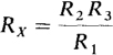
Presumably, R1 and R3 are known standard resistances and a dial connected to R2 gives this resistance so that Rx can be solved for. Of course, a commercial Wheatstone bridge has dials that directly indicate Rx upon balance.
A good way to remember the bridge balance equation is to equate products of the resistances of opposite branch arms: R1 Rx = R2R3. Another way is to equate the ratio of the top and bottom resistances of one side to that of the other: R1/R3 = R2/Rx.
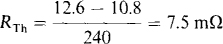
5.1 A car battery has an open-circuit terminal voltage of 12.6 V. The terminal voltage drops to 10.8 V when the battery supplies 240 A to a starter motor. What is the Thévenin equivalent circuit for this battery?
The Thévenin voltage is the 12.6-V open-circuit voltage (VTh = 12.6 V). The voltage drop when the battery supplies 240 A is the same drop that would occur across the Thévenin resistor in the Thévenin equivalent circuit because this resistor is in series with the Thévenin voltage source. From this drop,
5.2 Find the Thévenin equivalent circuit for a dc power supply that has a 30-V terminal voltage when delivering 400 mA and a 27-V terminal voltage when delivering 600 mA.
For the Thévenin equivalent circuit, the terminal voltage is the Thévenin voltage minus the drop across the Thévenin resistor. Consequently, from the two specified conditions of operation,
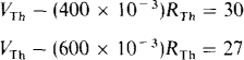
Subtracting,

from which

This value of RTh substituted into the first equation gives

5.3 Find the Thévenin equivalent circuit for a battery box containing four batteries with their positive terminals connected together and their negative terminals connected together. The open-circuit voltages and internal resistances of the batteries are 12.2 V and 0.5 Ω, 12.1 V and 0.1 Ω, 12.4 V and 0.16 Ω, and 12.4 V and 0.2 Ω.
The first step is to transform each voltage source to a current source. The result is four ideal current sources and four resistors, all in parallel. The next step is to add the currents from the current sources and also to add the conductances of the resistors, the effect of which is to combine the current sources into a single current source and the resistors into a single resistor. The final step is to transform this source and resistor to a voltage source in series with a resistor to obtain the Thévenin equivalent circuit.
The currents of the equivalent sources are

which add to

The conductances add to
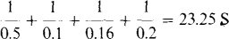
From this current and conductance, the Thévenin voltage and resistance are

5.4 Find the Norton equivalent circuit for the power supply of Prob. 5.2 if the terminal voltage is 28 V instead of 27 V when the power supply delivers 600 mA.
For the Norton equivalent circuit, the load current is the Norton current minus the loss of current through the Norton resistor. Consequently, from the two specified conditions of operation,
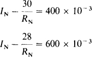
Subtracting,
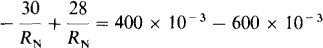
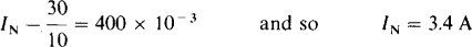
or

Substituting this into the first equation gives
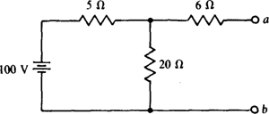
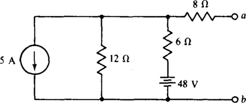
5.5 What resistor draws a current of 5 A when connected across terminals a and b of the circuit shown in Fig. 5-10?
Fig. 5-10
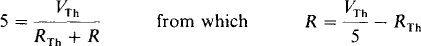
A good approach is to use Thévenin’s theorem to simplify the circuit to the Thévenin equivalent of a VTh voltage source in series with an RTh resistor. Then the load resistor R is in series with these, and Ohm’s law can be used to find R:
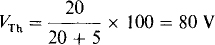
The open-circuit voltage at terminals a and b is the voltage across the 20-Ω resistor since there is 0 V across the 6-Ω resistor because no current flows through it. By voltage division this voltage is
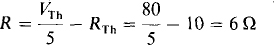
RTh is the resistance at terminals a and b with the 100-V source replaced by a short circuit. This short circuit places the 5-and 20-Ω resistors in parallel for a net resistance 5||20 = 4Ω. So. RTh = 6 + 4 =10Ω.
With VTh and RTh known, the load resistance R for a 5-A current can be found from the previously derived equation:
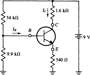
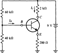
5.6 In the circuit shown in Fig. 5-11, find the base current IB if Ic = 30IB. The base current is provided by a bias circuit consisting of 54- and 9.9-kΩ resistors and a 9-V source. There is a 0.7-V drop from base to emitter.
Fig. 5-11
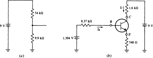
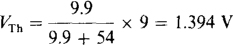
One way to find the base current is to break the circuit at the base lead and determine the Thévenin equivalent of the bias circuit. For this approach it helps to consider the 9-V source to be two 9-V sources, one of which is connected to the 1.6-kΩ collector resistor and the other of which is connected to the 54-kΩ bias resistor. Then the bias circuit appears as illustrated in Fig. 5-12a. From it, the voltage VTh is, by voltage division,
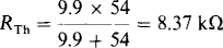
Replacing the 9-V source by a short circuit places the 54- and 9.9-kΩ resistors in parallel for an RTh of
and the circuit simplifies to that shown in Fig. 5-12b.
Fig. 5-12
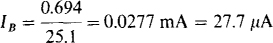
From KVL applied to the base loop, and from the fact that IC + IB = 31IB flows through the 540-Ω emitter resistor,

from which
Of course, the simplifying kilohm-milliampere method was used in some of the calculations.
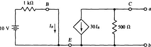
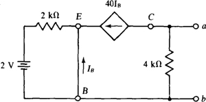
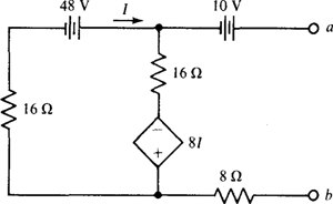
5.7 Find the Thévenin equivalent circuit at terminals a and b of the circuit with transistor model shown in Fig. 5-13.
Fig. 5-13
The open-cirCuit voltage is 500 × 30IB = 15 000IB, positive at terminal b. From the base circuit, IB = 10/1000 A = 10 mA. Substituting in for IB gives

The best way to find RTh is to deactivate the independent 10-V source and determine the resistance at terminals a and b. With this source deactivated, IB = 0 A, and so 30IB = 0 A, which means that the dependent current source acts as an open circuit—it produces zero current regardless of the voltage across it. The result is that the resistance at terminals a and b is just the shown 500 Ω.
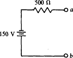
The Thévenin equivalent circuit is a 500-Ω resistor in series with a 150-V source that has its positive terminal toward terminal b, as shown-in Fig. 5-14.
Fig. 5-14
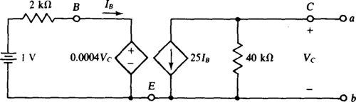
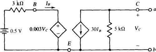
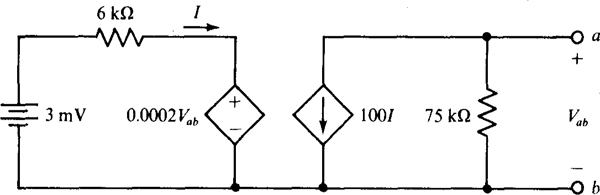
5.8 What is the Norton equivalent circuit for the transistor circuit shown in Fig. 5-15?
Fig. 5-15
A good approach is to first find Isc, which is the Norton current IN; next find Voc, which is the Thévenin voltage VTh; and then take their ratio to obtain the Norton resistance RN, which is the same as RTh.
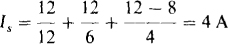
Placing a short circuit across terminals a and b makes Vc = 0 V, which in turn causes the dependent voltage source in the base circuit to be a short circuit. As a result, IB = 1/2000 A = 0.5 mA. This short circuit also places 0 V across the 40-kΩ resistor, preventing any current flow through it. So, all the 25/B = 25 × 0.5 = 12.5 mA current from the dependent current source flows through the short circuit in a direction from terminal b to terminal a: Isc = IN = 12.5 mA.
The open-circuit voltage is more difficult to find. From the collector circuit, Vc = (–25IB)(40 000) = — 106IB. This substituted into the KVL equation for the base circuit produces an equation in which IB is the only unknown:

So, IB = 1/1600 A = 0.625 mA, and Vc = -106IB = – 106(0.625 × 10⁻³) = –625 V. The result is that Voc = 625 V, positive at terminal b.
In the calculation of RN, signs are important when, as here, a circuit has dependent sources that can cause RN to be negative. From Fig. 5-3b, RTh = RN is the ratio of the open-circuit voltage referenced positive at terminal a and the short-circuit current referenced from terminal a to terminal b. Alternatively, both references can be reversed, which is convenient here. So,
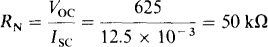
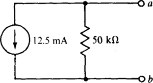
The Norton equivalent circuit is a 50-kΩ resistor in parallel with a 12.5-mA current source that is directed toward terminal b, as shown in Fig. 5-16.
Fig. 5-16
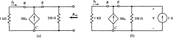
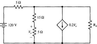
5.9 Directly find the output resistance of the circuit shown in Fig. 5-15.
Figure 5-17 shows the circuit with the 1-V independent source deactivated and a 1-A current source applied at the output a and b terminals. From Ohm’s law applied to the base circuit,
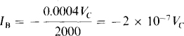
Fig. 5-17
Nodal analysis applied to the top node of the collector circuit gives

upon substitution for IB. The solution is Vc = 50 000 V, and so Rout, = RTh = 50 kΩ. This checks with the RN = RTh answer from the Prob. 5.8 solution in which the RN = RTh = VocIsc approach was used.
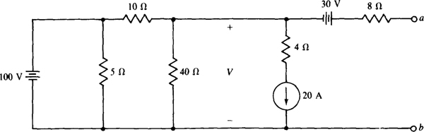
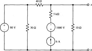
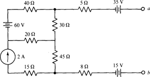
5.10 Find the Thévenin equivalent of the circuit shown in Fig. 5-18.
Fig. 5-18
The Thévenin or open-circuit voltage, positive at terminal a, is the indicated V plus the 30 V of the 30-V source. The 8-Ω resistor has no effect on this voltage because there is zero current flow through it as a result of the open circuit. With zero current there is zero voltage. V can be found from a single nodal equation:
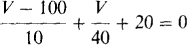
Multiplying by 40 and simplifying produces

So, VTh = – 80 + 30 = — 50 V. Notice that the 5-Ω and 4-Ω resistors have no effect on VTh
Figure 5-19a shows the circuit with the voltage sources replaced by short circuits and the current source by an open circuit. Notice that the 5-Ω resistor has no effect on RTh because it is shorted, and neither does the 4-Ω resistor because it is in series with an open circuit. Since the resistor arrangement in Fig. 5-19a is series-parallel, RTh is easy to calculate by combining resistances: RTh = 8 + 40 || 10 = 16Ω.
Fig. 5-19
The fact that neither the 5-Ω nor the 4-Ω resistor has an effect on VTh and RTh leads to the generalization that resistors in parallel with ideal voltage sources, and resistors in series with ideal current sources, have no effect on voltages and currents elsewhere in a circuit.
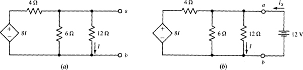
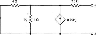
5.11 Obtain the Thévenin equivalent of the circuit of Fig. 5-20a.
By inspection, VTh = 0 V because the circuit does not contain any independent sources. For a determination of RTh, it is necessary to apply a source and calculate the ratio of the source voltage to the source current. Any independent source can be applied, but often a particular one is best. Here, if a 12-V voltage source is applied positive at terminal a, as shown in Fig. 5-20b, then I = 12/12 = 1 A, which is the most convenient current. As a result, the dependent source provides a voltage of 8I = 8 V. So, by KCL,
Finally,
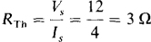
Fig. 5-20
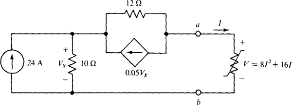
5.12 For the circuit of Fig. 5-21, obtain the Thévenin equivalent to the left of the a-b terminals. Then use this equivalent in determining I.
Fig. 5-21
The Thévenin equivalent can be obtained by determining any two of VTh, RTh, and Isc. By inspection, it appears that the two easiest to determine are VTh and KVL.
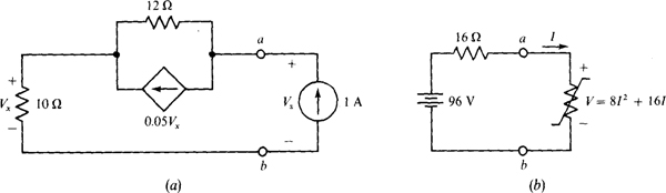
If the circuit is opened at the a-b terminals, all 24 A of the independent current source must flow through the 10-Ω resistor, making Vx = 10(24) = 240 V. Consequently, the dependent current source provides a current of 0.05 Vx = 0.05(240) = 12 A, all of which must flow through the 12-Ω resistor. As a result, by KVL,

Because of the presence of the dependent source, RTh must be found by applying a source and determining the ratio of the source voltage to the source current. The preferable source to apply is a current source, as shown in Fig. 5-22a. If this source is 1 A, then Vx = 10(1)= 10 V, and consequently the dependent current source provides a current of 0.05(10) = 0.5 A. Since this is one-half the source current, the other half must flow through the 12-Ω resistor. And so, by KVL,

Then,
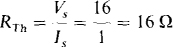
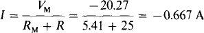
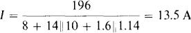
Figure 5-22b shows the Thévenin equivalent connected to the nonlinear load of the original circuit. The current I is much easier to calculate with this circuit. By KVL,

Fig. 5-22
Applying the quadratic formula gives
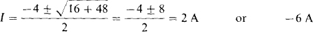
Only the 2-A current is physically possible because current must flow out of the positive terminal of the Thévenin voltage source, which means that I must be positive. So, I = 2 A.
5.13 Figure 5-23a shows an emitter-follower circuit for obtaining a low output resistance for resistance matching. Find Rout.
Because the circuit has a dependent source but no independent sources, Rout must be found by applying a source at the output terminals, preferably a 1-A current source as shown in Fig. 5-23b.
Fig. 5-23
From KCL applied at the top node,

But from Ohm’s law applied to the l-kΩ resistor, IB = — V/1000. With this substitution the equation becomes
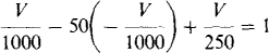
from which V = 18.2 V. Then Rout = V/1 = 18.2 Ω, which is much smaller than the resistance of either resistor in the circuit.
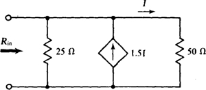
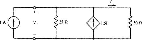
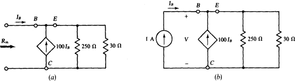
5.14 Find the input resistance Rin of the circuit shown in Fig. 5-24.
Fig. 5-24
Since this circuit has a dependent source but no independent sources, the approach to finding the input resistance is to apply a source at the input. Then the input resistance is equal to the input voltage divided by the input current. A good source to apply is a 1-A current, as shown in Fig. 5-25.
Fig. 5-25

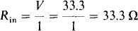
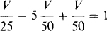
But from the right-hand branch, I = V/50. With this substitution the equation becomes

the solution to which is V = 33.3 V. So, the input resistance is
5.15 Find the input resistance of the circuit shown in Fig. 5-24 if the dependent current source has a current of 5I instead of 1.5I.
For a 1-A current source applied at the input terminals, the nodal equation at the top node is
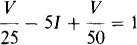
But, from the right-hand branch, I = V/50. With this substitution the equation is
from which V = —25 V. Thus, the input resistance is Rin = „25/1 = — 25 Ω.
A negative resistance may be somewhat disturbing to the mind when first encountered, but it is physically real even though it takes a transistor circuit, an operational amplifier, or the like to obtain it. Physically, a negative input resistance means that the circuit supplies power to whatever source is applied at the input, with the dependent source being the source of power.
5.16 Figure 5-26a shows an emitter-follower circuit for obtaining a large input resistance for resistance matching. The load is a 30-Ω. resistor, as shown. Find the input resistance Rin.
Because the circuit has a dependent source and no independent sources, the preferable way to find Rin is from the input voltage when a 1-A current source is applied, as shown in Fig. 5-26b. Here, Is = 1 A, and so the total current to the parallel resistors is IB + 100IB = 101IB = 101 A, and the voltage V is

The input resistance is Rin = V/1 = 2.7 kΩ, which is much greater than the 30 Ω of the load.
Fig. 5-26
5.17 What is the maximum power that can be drawn from a 12-V battery that has an internal resistance of 0.25 Ω?
A resistive load of 0.25 Ω draws maximum power because it has the same resistance as the Thévenin or internal resistance of the source. For this load, half the source voltage drops across the load, making the power 670.25 = 144 W.
5.18 What is the maximum power that can be drawn by a resistor connected to terminals a and b of the circuit shown in Fig. 5-15?
In the solution to Prob. 5.8, the Thévenin resistance of the circuit shown in Fig. 5-15 was found to be 50 kí and the Norton current was found to be 12.5 mA. So, a load resistor of 50 kΩ absorbs maximum power. By current division, half the Norton current flows through it, producing a power of

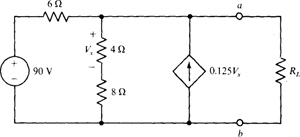
5.19 In the circuit of Fig. 5-27, what resistor RL will absorb maximum power and what is this power?
Fig. 5-27
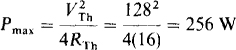
For maximum power transfer, RL = RTh and pmax = V2Th/(4RTh). So, it is necessary to obtain the Thévenin equivalent of the portion of the circuit to the left of the a and b terminals.
If RL is replaced by an open circuit, then the current I is, by current division,
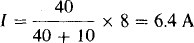
Consequently, the dependent voltage source provides a voltage of 10(6.4) = 64 V. Then, by KVL,

It is convenient to use the short-circuit current approach in determining Rn. If a short circuit is placed across terminals a and b, all components of the circuit of Fig. 5-27 are in parallel. Consequently, the voltage drop, top to bottom, across the 10-Χ resistor of 10I is equal to the —10I voltage drop across the dependent voltage source. Since the solution to 10I = —10I is I = 0 A, there is a zero voltage drop across both resistors, which means that all the 8 A of the current source must flow down through the short circuit. So, Isc = 8 A and
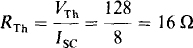
Thus, RL = 16 Ω for maximum power absorption. Finally, this power is
5.20 In the circuit of Fig. 5-28, what resistor RL will absorb maximum power and what is this power?
Fig. 5-28
It is, of course, necessary to obtain the Thévenin equivalent to the left of the a and b terminals. The Thévenin voltage VTh will be obtained first. Observe that the voltage drop across the 4-Ω resistor is Vx, and that this resistor is in series with an 8-Ω resistor. Consequently, by voltage division performed in a reverse manner, the open-circuit voltage is VTh = Vab = 3VX. Next, with R, removed, applying KCL at the node that includes terminal a gives
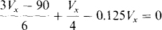
the solution to which is Vx = 24 V. So, VTh = 3VX = 3(24) = 72 V.
By inspection of the circuit, it should be fairly apparent that it is easier to use Isc to obtain RTh than it is to determine RTh directly. If a short circuit is placed across terminals a and h, then Vx = 0 V, and so no current flows in the 4-Ω resistor and there is no current flow in the dependent current source. Consequently, Isc = 90/6 = 15 A. Then,
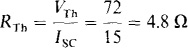
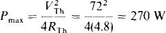
which is the resistance that RL should have for maximum power absorption. Finally,
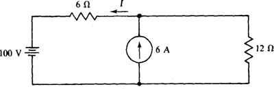
5.21 Use superposition to find the power absorbed by the 12-Ω resistor in the circuit shown in Fig. 5-29.
Fig. 5-29
Superposition cannot be used to find power in a dc circuit because the method applies only to linear quantities, and power has a squared voltage or current relation instead of a linear one. To illustrate, the current through the 12-Ω resistor from the 100-V source is, with the 6-A source replaced by an open circuit, 100/(12 + 6) = 5.556 A. The corresponding power is 5.5562 × 12 = 370 W. With the voltage source replaced by a short circuit, the current through the 12-Ω resistor from the 6-A current source is, by current division, [6/(12 + 6)](6) = 2 A. The corresponding power is 22 × 12 = 48 W. So, if superposition could be applied to power, the result would be 370 + 48 = 418 W for the power dissipated in the 12-Ω resistor.
Superposition does, however, apply to currents. So, the total current through the 12-Ω resistor is 5.556 + 2 = 7.556 A, and the power consumed is 7.5562 × 12 = 685 W, which is much different than the 418 W found by erroneously applying superposition to power.
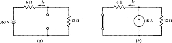
5.22 In the circuit shown in Fig. 5-29, change the 100-V source to a 360-V source, and the 6-A current source to an 18-A source, and use superposition to find the current I.
Figure 5-30a shows the circuit with the current source replaced by an open circuit. Obviously, the component Iv of I from the voltage source is Iv = –360/(6 + 12) = –20 A. Figure 5-30/b shows the circuit with the voltage source replaced by a short circuit. By current division, Ic, the current-source component of I, is Ic = [12/(12 + 6)](18) = 12 A. The total current is the algebraic sum of the current components: I = Iv + Ic = -20 + 12 = -8 A.
Fig. 5-30
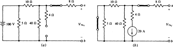
5.23 For the circuit shown in Fig. 5-18, use superposition to find VTh referenced positive on terminal a.
Clearly, the 30-V source contributes 30 V to VTh because this source, being in series with an open circuit, cannot cause any currents to flow. Zero currents mean zero resistor voltage drops, and so the only voltage in the circuit is that of the source.
Figure 5-31a shows the circuit with all independent sources deactivated except the 100-V source. Notice that the voltage across the 40-Ω resistor appears across terminals a and b because there is a zero voltage drop across the 8-Ω resistor. By voltage division this component of VTh is
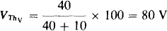
Figure 5-31b shows the circuit with the current source as the only independent source. The voltage across the 40-Ω resistor is the open-circuit voltage since there is a zero voltage drop across the 8-Ω resistor. Note that the short circuit replacing the 100-V source prevents the 5-Ω resistor from having an effect, and also it places the 40- and 10-Ω resistors in parallel for a net resistance of 40|| 10 = 8 Ω. So, the component of VTh from the current source is VThc = – 20 × 8 = – 160 V.
Fig. 5-31
VTh is the algebraic sum of the three components of voltage:

Notice that finding VTh by superposition requires more work than finding it by nodal analysis, as was done in the solution to Prob. 5.10.
5.24 Use superposition to find VTh for the circuit shown in Fig. 5-15.
Although this circuit has three sources, superposition cannot be used since two of the sources are dependent. Only one source is independent. The superposition theorem does not apply to dependent sources.
5.25 Use Millman’s theorem to find the current flowing to a 0.2-Ω resistor from four batteries operating in parallel. Each battery has a 12.8-V open-circuit voltage. The internal resistances are 0.1, 0.12, 0.2, and 0.25 Ω.
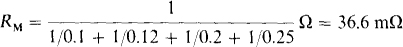
Because the battery voltages are the same, being 12.8 V, the Millman voltage is VM = 12.8 V. The Millman resistance is the inverse of the sum of the conductances:
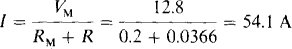
Of course, the resistor current equals the Millman voltage divided by the sum of the Millman and load resistances:
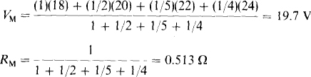
5.26 Use Millman’s theorem to find the current drawn by a 5-Ω resistor from four batteries operating in parallel. The battery open-circuit voltages and internal resistances are 18 V and 1 Ω, 20 V and 2 Ω, 22 V and 5 Ω, and 24 V and 4 Ω.
The Millman voltage and resistance are
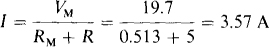
The current is, of course, the Millman voltage divided by the sum of the Millman and load resistances:
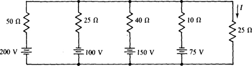
5.27 Use Millman’s theorem to find I for the circuit shown in Fig. 5-32.
Fig. 5-32
The Millman voltage and resistance are

And so
5.28 Transform the Δ shown in Fig. 5-33a to the Y shown in Fig. 5-33b for (a) R1 = R2 = R3 = 36 Ω, and (b) Rx = 20 Ω, R2 = 30 Cl, and R3 = 50 Ω.
(a) For Δ resistances of the same value, Ry = RΔ/3. So, here, RA = RB = Rc = 36/3 = 12 Ω.
(b) The denominators of the RY formulas are the same: R1 + R2 + R3 = 20 + 30 + 50 = 100 Ω. The numerators are products of the adjacent resistor resistances if the Y is placed inside the Δ:

Fig. 5-33
5.29 Transform the Y shown in Fig. 5-33b to the A shown in Fig. 5-33a for (a) RA = RB = Rc = 5 Ω, and (b) RA = 10 Ω, RB = 5 Ω, Rc = 20 Ω.
(a) For Y resistances of the same value: RA = 3Ry. So, here, R1 = R2 R3 = 3 × = 5 = 15 Ω
(b) The numerators of the RA formulas are the same: RARB + RARC + RB Rc = 10 × 5 + 10 × 20 + 5 × 20 = 350. The denominators of the RA formulas are the resistances of the Y arms opposite the A arms if the Y is placed inside the Δ. Thus,

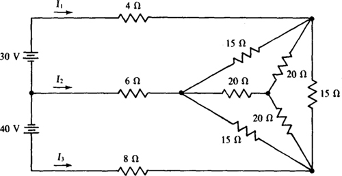
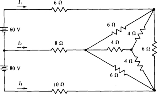
5.30 Use a Δ-to-Y transformation in finding the currents I1, I2, and I3 for the circuit shown in Fig. 5-34.
Fig. 5-34
The Δ of 15-Ω resistors transforms to a Y of 15/3 = 5-Ω resistors that are in parallel with the Y of 20-Ω resistors. It is not obvious that they are in parallel, and in fact they would not be if the resistances for each Y were not all the same value. When, as here, they are the same value, an analysis would show that the middle nodes are at the same potential, just as if a wire were connected between them. So, corresponding resistors of the two Y’s are in parallel, as shown in Fig. 5-35a. The two Y’s can be reduced to the single Y shown in Fig. 5-35b, in which each Y resistance is 5||20 = 4 Ω. With this Y replacing the Δ-Y combination, the circuit is as shown in Fig. 5-35c.
Fig. 5-35
With the consideration of It and I3 as loop currents, the corresponding KVL equations are

the solutions to which are I, = 0.88 A and I3 = 1.42 A. Then, from KCL applied at the right-hand node, I2 = –I1 – I3 = –2.3 A.
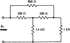
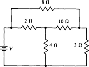
5.31 Using a Y-to-Δ transformation, find the total resistance RT of the circuit shown in Fig. 5-36, which has a bridged-T attenuator.
Fig. 5-36
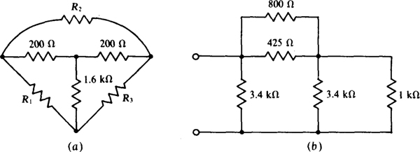
Fig. 5-37
Figure 5-37a shows the T part of the circuit inside a Δ as an aid in finding the A resistances. From the Y-to-Δ transformation formulas,
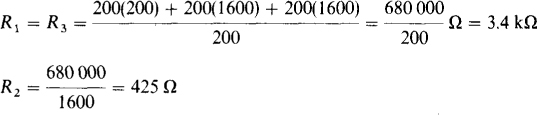
As a result of this transformation, the circuit becomes series-parallel as shown in Fig. 5-37b, and the total resistance is easy to find:

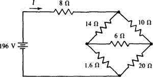
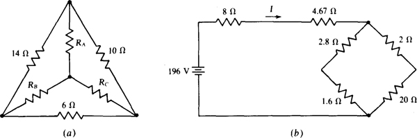
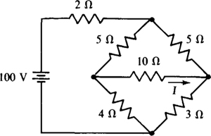
5.32 Find I for the circuit shown in Fig. 5-38 by using a Δ-Y transformation.
Fig. 5-38
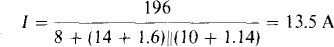
The bridge simplifies to a series-parallel configuration from a transformation of either the top or bottom Δ to a Y, or the left- or right-hand Y to a Δ. Perhaps the most common approach is to transform one of the Δ’s to a Y, although the work required is about the same for any type of transformation. Figure 5-39a shows the top Δ enclosing a Y as a memory aid for the transformation of this Δ to a Y. All three Y formulas have the same denominator: 14 + 10 + 6 = 30. The numerators, though, are the products of the resistances of the adjacent Δ resistors:

With this transformation the circuit simplifies to that shown in Fig. 5-39b in which all the resistors are in series-parallel. From it,
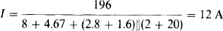
Fig. 5-39
5.33 In the circuit shown in Fig. 5-38, what resistor R replacing the 20-Ω resistor causes the bridge to be balanced? Also, what is I then?
For balance, the product of the resistances of opposite bridge arms are equal:

With the bridge in balance, the center arm can be considered as an open circuit because it carries no current. This being the case, and because the bridge is a series-parallel arrangement, the current I is
Alternatively, the center arm can be considered to be a short circuit because both ends of it are at the same potential. From this point of view,
which is, of course, the same.
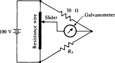
5.34 The slide-wire bridge shown in Fig. 5-40 has a uniform resistance wire that is 1 m long. If balance occurs with the slider at 24 cm from the top, what is the resistance of Rx?
Let Rw be the total resistance of the resistance wire. Then the resistance from the top of the wire to the slider is (24/100)Rw. = 0.24Rw. That from the slider to the bottom of the wire is (76/100)Rw. = 0.76Rw. So, the bridge resistances are 0.24Rw., 0.76Rw, 30 Ω, and Rx. These inserted into the bridge balance equation give
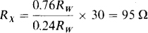
Fig. 5-40
5.35 A car battery has a 12.1-V terminal voltage when supplying 10 A to the car lights. When the starter motor is turned over, the extra 250 A drawn drops the battery terminal voltage to 10.6 V. What is the Thévenin equivalent circuit of this battery?
Ans. 6 mΩ, 12.16 V
5.36 In full sunlight a 2- by 2-cm solar cell has a short-circuit current of 80 mA, and the current is 75 mA for a terminal voltage of 0.6 V. What is the Norton equivalent circuit?
Ans. 120 Ω, 80 mA
5.37 Find the Thévenin equivalent of the circuit shown in Fig. 5-41. Reference VTh positive toward terminal a.
Fig. 5-41
Ans. 12 Ω, 12 V
5.38 In the circuit shown in Fig. 5-41, change the 5-A current source to a 7-A current source, the 12-Ω resistor to an 18-Ω resistor, and the 48-V source to a 96-V source. Then find the Norton equivalent circuit with the current arrow directed toward terminal a.
Ans. 12.5 Ω, 3.24 A
5.39 For the circuit shown in Fig. 5-42, find the Norton equivalent with IN referenced positive toward terminal a.
Fig. 5-42
Ans. 4 Ω, –3 A
5.40 Find the Norton equivalent of the circuit of Fig. 5-43. Reference IN up.
Fig. 5-43
Ans. 8 Ω, 8 A
5.41 Determine the Norton equivalent of the circuit of Fig. 5-44. Reference IN up.
Fig. 5-44
Ans. 78 n, 1.84 A
5.42 Find the Thévenin equivalent of the grounded-base transistor circuit shown in Fig. 5-45. Reference VTh positive toward terminal a.
Fig. 5-45
Ans. 4 kΩ, 3.9 V
5.43 In the transistor circuit shown in Fig. 5-46, find the base current IB if Ic = 40IB. There is a 0.7-V drop from base to emitter.
Fig. 5-46
Ans. 90.1 θA
5.44 Find the Thévenin equivalent of the transistor circuit shown in Fig. 5-47. Reference VTh positive toward terminal a.
Fig. 5-47
Ans. 5.88 kΩ, –29.4 V
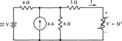
5.45 Find I in the circuit shown in Fig. 5-48, which contains a nonlinear element having a V-I relation of V = 3I2. Use Thévenin’s theorem and the quadratic formula.
Fig. 5-48
Ans. 2 A
5.46 Find the Thévenin equivalent of the circuit of Fig. 5-49. Reference VTh positive toward terminal a.
Fig. 5-49
Ans. 18.7 Ω, 26 V
5.47 Obtain the Thévenin equivalent of the circuit of Fig. 5-50.
Fig. 5-50
Ans. –1.5 Ω, 0 V
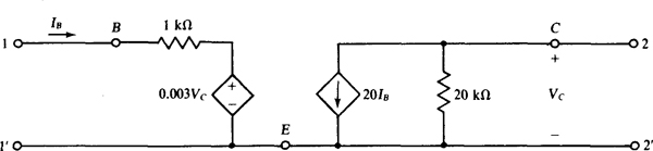
5.48 Find the input resistance at terminals 1 and 1’ of the transistor circuit shown in Fig. 5-51 if a 2-kΩ resistor is connected across terminals 2 and 2’.
Fig. 5-51
Ans. 88.1 kΩ
5.49 Find the output resistance at terminals 2 and 2’ of the transistor circuit shown in Fig. 5-51 if a source with a 1-kΩ internal resistance is connected to terminals 1 and 1’. In finding the output resistance remember to replace the source by its internal resistance.
Ans. 32.6 Ω
5.50 Find the input resistance at terminals 1 and 1’ of the transistor circuit shown in Fig. 5-52 if a 5-kΩ load resistor is connected between terminals 2 and 2’, from collector to emitter.
Fig. 5-52
Ans. 760 Ω
5.51 Find the output resistance at terminals 2 and 2’ of the transistor circuit shown in Fig. 5-52 if a source with a 500-Ω internal resistance is connected to terminals 1 and 1'.
Ans. 100 kΩ
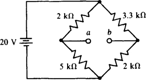
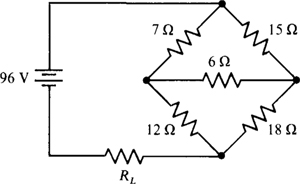
5.52 What resistor connected between terminals a and b in the bridge circuit shown in Fig. 5-53 absorbs maximum power and what is this power?
Fig. 5-53
Ans. 2.67 kΩ, 4.25 mW
5.53 What will be the reading of a zero-resistance ammeter connected across terminals a and b of the bridge circuit shown in Fig. 5-53? Assume that the ammeter is connected to have an upscale reading. What will be the reading if a 1-kΩ resistor is in series with the ammeter?
Ans. 2.52 mA, 1.83 mA
5.54 Some solar cells are interconnected for increased power output. Each has the specifications given in Prob. 5.36. What area of solar cells is required for a power output of 1 W? Assume a matching load.
Ans. 20.8 cm2
5.55 In the circuit of Fig. 5-54, what resistor RL will absorb maximum power, and what is this power?
Fig. 5-54
Ans. 3.33 Ω, 480 W
5.56 In the circuit of Fig. 5-55, what resistor connected across terminals a and b will absorb maximum power, and what is this power?
Fig. 5-55
Ans. 100 kΩ, 62.5 θW
5.57 For the circuit shown in Fig. 5-41, use superposition to find the contribution of each source to VTh if it is referenced positive toward terminal a.
Ans. 32 V from the 48-V source, — 20 V from the 5-A source
5.58 For the circuit shown in Fig. 5-42, use superposition to find the contribution of each source to the current in a short circuit connected between terminals a and b. The short-circuit current reference is from terminal a to terminal b.
Ans. 5 A from the 60-V source, — 8 A from the 8-A source
5.59 In the circuit shown in Fig. 5-48, replace the nonlinear resistor with an open circuit and use superposition to find the contribution of each source to the open-circuit voltage referenced positive at the top.
Ans. 13.2 V from the 22-V source, 9.6 V from the 4-A source
5.60 An automobile generator operating in parallel with a battery energizes a 0.8-Ω load. The open-circuit voltages and internal resistances are 14.8 V and 0.4 Ω for the generator, and 12.8 V and 0.5 Ω for the battery. Use Millman’s theorem to find the load current.
Ans. 13.6 A
5.61 For the automobile circuit of Prob. 5.60 use superposition to find the load current contribution from each source.
Ans. 8.04 A from the generator, 5.57 A from the battery
5.62 Transform the A shown in Fig. 5-56a to the Y in Fig. 5-56b for R1 = 2kΩ, R2 = 4 kΩ, and R3 = 6kΩ.
Ans. RA = 667 Ω, RB = 2 kΩ, Rc = 1 kΩ
5.63 Repeat Prob. 5.62 for R1 = 8 Ω, R2 = 5 Ω, and R3 = 7 Ω.
Ans. RA = 2Ω, RB = 1.75 Ω, Rc = 2.8 Ω
Fig. 5-56
5.64 Transform the Y shown in Fig. 5-56b to the A in Fig. 5-56a for RA = 12Ω, RB = 15Ω, and Rc = 18 Ω.
Ans. R1 = 44.4 Ω, R2 = 37 Ω, R3 = 55.5 Ω
5.65 Repeat Prob. 5.64 for Rx = 10 kΩ, KB = 18kΩ, and Rc = 12 kΩ.
Ans. R1 = 28.7 kΩ, R2 = 43 kΩ, R3 = 51.6 kΩ
5.66 For the lattice circuit shown in Fig. 5-57, use a Δ-Y transformation to find the V that makes I = 3 A.
Ans. 177 V
Fig. 5-57
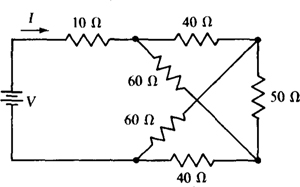
5.67 Use a Δ-Y transformation to find the currents in the circuit shown in Fig. 5-58.
Fig. 5-58
Ans. I1 = 7.72 A, I2 = –0.36 A, I3 = –7.36 A
5.68 Use a Δ-to-Y transformation in finding the voltage V that causes 2 A to flow down through the 3-Ω resistor in the circuit shown in Fig. 5-59.
Fig. 5-59
Ans. 17.8 V
5.69 In the lattice circuit shown in Fig. 5-57, what resistor substituted for the top 40-Ω resistor causes zero current flow in the 50-Ω resistor?
Ans. 90 Ω
5.70 If in the slide-wire bridge shown in Fig. 5-40, balance occurs with the slider at 67 cm from the top, what is the resistance Rx?
Ans. 14.8 Ω.
5.71 Use a A-Y transformation to find I in the circuit shown in Fig. 5-60. Remember that for a Δ-Y transformation, only the voltages and currents external to the Δ and Y do not change.
Fig. 5-60
Ans. 0.334 A
5.72 In the circuit of Fig. 5-61, what resistor RL will absorb maximum power, and what is this power?
Fig. 5-61
Ans. 12 Ω, 192 W
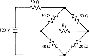
5.73 In the circuit of Fig. 5-62, what resistor RL will absorb maximum power, and what is this power?
Fig. 5-62
Ans. 30 Ω, 1.48 W