V and the most convenient source current is IT = A.
With two minor modifications, the dc network theorems discussed in Chap. 5 apply as well to ac phasor-domain circuits: The maximum power transfer theorem has to be modified slightly for circuits containing inductors or capacitors, and the same is true of the superposition theorem if the time-domain circuits have sources of different frequencies. Otherwise, though, the applications of the theorems for ac phasor-domain circuits are essentially the same as for dc circuits.
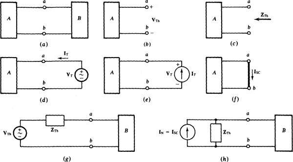
In the application of Thévenin’s or Norton’s theorems to an ac phasor-domain circuit, the circuit is divided into two parts, A and B, with two joining wires, as shown in Fig. 14-la. Then, for Thévenin’s theorem applied to part A, the wires are separated at terminals a and b, and the open-circuit voltage VTh, the Thévenin voltage, is found referenced positive at terminal a, as shown in Fig. 14-lb. The next step, as shown in Fig. 14-1 c, is to find Thévenin’s impedance ZTh of part A at terminals a and b. For Thévenin’s theorem to apply, part A must be linear and bilateral, just as for a dc circuit.
There are three ways to find ZTh. For one way, part A must have no dependent sources. Also, preferably, the impedances are arranged in a series-parallel configuration. In this approach, the independent sources in part A are deactivated, and then ZTh is found by combining impedances and admittances—that is, by circuit reduction.
If the impedances of part A are not arranged series-parallel, it may not be convenient to use circuit reduction. Or, it may be impossible, especially if part A has dependent sources. In this case, ZTh can be found in a second way by applying a voltage source as shown in Fig. 14-1d or a current source as shown in Fig. 14-le, and finding ZTh = VT/IT. Often., the mosit convenient source voltage is VT = V and the most convenient source current is IT = A.
Fig. 14-1
The third way to find ZTh is to apply a short circuit across terminals a and b, as shown in Fig. 14-1f, then find the short-circuit current Isc, and use it in ZTh = VTh/Isc. Of course, VTh must also be known. For this approach, part A must have independent sources, and they must not be deactivated.
In the circuit shown in Fig. 14-lg, the Thévenin equivalent produces the same voltages and currents in part B that the original part A does. But only the part B voltages and currents remain the same; those in part A almost always change, except at the a and b terminals.
For the Norton equivalent circuit shown in Fig. 14-1h, the Thévenin impedance is in parallel with a current source that provides a current up that is equal to the short-circuit current down in the circuit shown in Fig. 14-1f. The Norton equivalent circuit also produces the same part B voltages and currents that the original part A does.
Because of the relation VTh = IscZTh, any two of the three quantities VTh, Isc, and ZTh can be found from part A and then this equation used to find the third quantity if it is needed for the application of either Thévenin’s or Norton’s theorem. Obviously, PSpice can be used to obtain the needed two quantities, one at a time, as should be apparent. However, the.TF feature explained in Prob. 7.5 cannot be used for this since its use is limited to dc analyses.
The load that absorbs maximum average power from a circuit can be found from the Thévenin equivalent of this circuit at the load terminals. The load shou’id have a reactance that cancels the reactance of this Thévenin impedance because reactance does not a’bsorb any average power but does limit the current. Obviously, for maximum power transfer, there should be no reactance limiting the current flow to the resistance part of the load. This, in turn, means that the load and Thévenin reactances must be equal in magnitude but opposite in sign.
With the reactance cancellation, the overall circuit becomes essentially purely resistive. As a result, the rule for maximum power transfer for the resistances is the same as that for a dc circuit: The load resistance must be equal to the resistance part of the Thévenin impedance. Having the same resistance but a reactance that differs only in sign, the load impedance for maximum power transfer is the conjugate of the Thévenin impedance of the circuit connec ted to t he load:  Also, because the overall circuit is purely resistive, the maximum power absorbed by the load is the same as for a dc circuit:
  in which VTh is the rms value of the Thé venin voltage VTh and RTh is the resistance part of ZTh.
If, in an ac time-domain circuit, the independent sources operate at the same frequency, the superposition theorem for the corresponding phasor-domain circuit is the same as for a dc circuit. That is, the desired voltage or current phasor contribution is found from each individual source or combination of sources, and then the various contributions are algebraically added to obtain the desired voltage or current phasor. Independent sources not involved in ai particular solution are deactivated, but dependent sources are left in the circuit.
For a circuit in which all sources have the; same frequency, an analysis with the superposition theorem is usually more work than a standard mesh, loop, or nodal analysis with all sources present. But the superposition theorem is essential if a time-domain circuit has inductors or capacitors and has sources operating at different frequencies. Since the reactances depend on the radian frequency, the same phasor-domain circuit cannot be used for all sources if they do not have the same frequency. There must be a different phasor-domain circuit for each different radian frequency, with the differences being in the reactances and in the deactivation of the various independent sources. Preferably, all independent sources having the same radian frequency are considered at a time, while the other independent sources are deactivated. This radian frequency is used to find the inductive and capacitive reactances for the corresponding phasor-domain circuit, and this circuit is analyzed to find the desired phasor. Then, the phasor is transformed to a sinusoid. This process is repeated for each different radian frequency of the sources. Finally, the individual sinusoidal responses are added to obtain the total response. Note that the adding is of the sinusoids and not of the phasors. This is because phasors of different frequencies cannot be validly added.
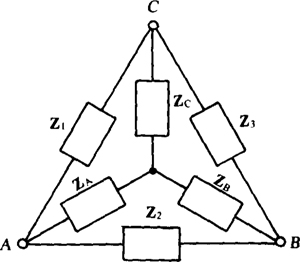
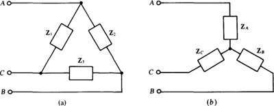
Chapter 5 presents the Y-Δ and Δ-Y transformation formulas for resistances. The only difference for impedances is in the use of Z’s instead of R’s. Specifically, for the Δ-Y arrangement shown in Fig. 14-2, the Y-to-Δ transformation formula; are

and the Δ-to-Y transformation formulas are

The Y-to-Δ transformation formulas all have the same numerator, which is the sum of the different products of the pairs of the Y impedances. Each denominator is the Y impedance shown in Fig. 14-2 that is opposite the impedance being found. The Δ-to-Y transformation formulas, on the other hand, have the same denominator, which is the sum of the Δ impedances. Each numerator is the product of the two Δ impedances shown in Fig. 14-2 that are adjacent to the Y impedance being found.
If all three Y impedances are the same ZY, the Y-to-Δ transformation formulas are the same: ZΔ = 3Zy. And if all three Δ impedances are the same ZΔ, the Δ-to-Y transformation formulas are the same: ZY = ZΔ/3.
Fig. 14-2
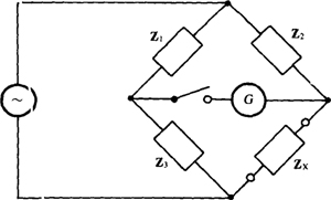
An ac bridge circuit, as shown in Fig. 14-3, can be used’ to measure inductance or capacitance in the same way that a Wheatstone bridge can be used to measure resistance, as explained in Chap. 5. The bridge components, except for the unknown impedance Zx, are typically just resistors and a capacitance standard—a capacitor the capacitance of which is known to.great precision. For a measurement, two of the resistors are varied until the galvanometer in the center arm reads zero when the switch is closed.
Fig. 14-3
Then the bridge is balanced, and the unknown impedance Zx can be found from the bridge balance equation Zx Z2Z3/Z1 which is the same as that for a Wheatstone bridge except for having Z’s instead of R’s.
In those Thévenin and Norton equivalent circuit problems in which the equivalent circuits are not shown, the equivalent circuits are as shown in Fig. 14-1g and h with VTh referenced positive at terminal a and IN = Isc referenced toward the same terminal. The Thévenin impedance is, of course, in series with the Thévenin voltage source in the Thévenin equivalent circuit, and is in parallel with the Norton current source in the Norton equivalent circuit.
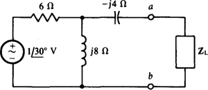
14.1 Find ZTh, VTh, and IN for the Thévenin and Norton equivalents of the circuit external to the load impedance ZL in the circuit shown in Fig. 14-4.
Fig. 14-4
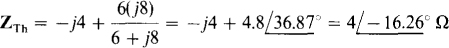
The Thévenin impedance ZTh is the impedance at terminals a and b with the load impedance removed and the voltage source replaced by a short circuit. From combining impedances,
Although either VTh or IN can be found next, VTh should be found because the — J4-Ω series branch makes IN more difficult to find. With an open circuit at terminals a and b, this branch has zero current and so zero voltage. Consequently, VTh is equal to the voltage drop across the j8-Ω impedance. By voltage division,

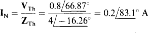
Finally,
14.2 If in the circuit shown in Fig. 14-4 the load is a resistor with resistance R, what value of R causes a 0.1-A rms current to flow through the load?
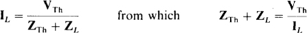
As is evident from Fig. 14-1g, the load current is equal to the Thévenin voltage divided by the sum of the Thévenin and load impedances:
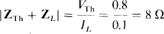
Since only the rms load current is specified, angles are not known, which means that magnitudes must be used. Substituting VTh = 0.8 V from the solution to Prob. 14.1,
Also from this solution, 

Because the magnitude of a complex number is equal to the square root of the sum of the squares of the real and imaginary parts,
Squaring and simplifying,
R2 + 7.68R + 16 = 64 or R2 7.68R.48=0
Applying the quadratic formula,
The positive sign must be used to obtain a physically significant positive resistance. So,
Note in the solution that the Thévenin and load impedances must be added before and not after the magnitudes are taken. This is because |ZTh|+|ZL|≠|ZL+ZTh|.
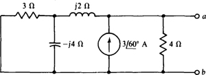
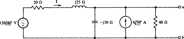
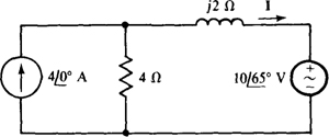
14.3 Find ZTh, VTh, and IN for the Thévenin and Norton equivalents of the circuit shown in Fig. 14-5.
Fig. 14-5
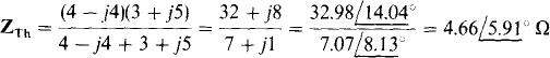
The Thévenin impedance ZTh is the impedance at terminals a and b with the current source replaced by an open circuit. By circuit reduction,
Multiplying the numerator and denominator by 3 — j4 gives
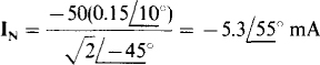
The short-circuit current is easy to find because, if a short circuit is placed across terminals a and b, all the source current flows through this short circuit: 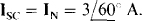 None of the source current can flow through the impedances because the short circuit places a zero voltage across them. Finally,

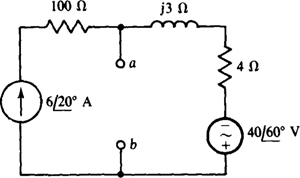
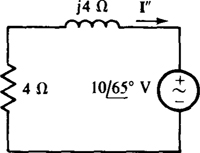
14.4 Find ZTh, VTh, and IN for the Thévenin and Norton equivalents of the circuit shown in Fig. 14-6.
Fig. 14-6
The Thévenin impedance ZTh is the impedance at terminals a and b, with the current source replaced by an open circuit and the voltage source replaced by a short circuit. The 100-Ω resistor is then in series with the open circuit that replaced the current source. Consequently, this resistor has no effect on ZTh. The j’3- and 4-Ω impedances are placed across terminals a and h by the short circuit that replaces the voltage source. As a result, 
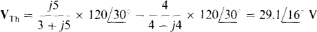
The short-circuit current Isc = IN will be found and used to obtain VTh. If a short circuit is placed across terminals a and b, the current to the right through the j3-Ω impedance is
because the short circuit places all the  of the voltage source across the 4- and j3-Ω impedances. Of course, the current to the right through the 100-Ω resistor is the
  source current. By KCL applied at terminal a, the short-circuit current is the difference between these currents:

Finally,

The negative signs for IN and Vth can, of course, be eliminated by reversing the references—that is, by having the Thévenin voltage source positive toward terminal b and the Norton current directed toward terminal b.
As a check, VTh can be found from the open-circuit voltage across terminals a and b. Because of this open circuit, all the source current must flow through the 4- and j3-Ω impedances. Consequently, from the right-hand half of the circuit, the voltage drop from terminal a to b is
which checks.
14.5 Find ZTh and VTh for the Thévenin equivalent of the circuit shown in Fig. 14-7.
Fig. 14-7
The Thevenin impedance ZTh can be found easily by replacing the voltage sources with short circuits and finding the impedances at terminals a and b. Since the short circuit places the right- and left-hand halves of the circuit in parallel,
A brief inspection of the circuit shows that the short-circuit current is easier to find than the open-circuit voltage. This current from terminal a to b is

Finally,

14.6 Find ZTh and VTh for the Thevenin equivalent of the circuit shown in Fig. 14-8.
Fig. 14-8
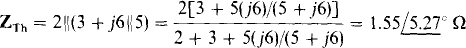
If the voltage source is replaced by a short circuit, the impedance ZTh at terminals a and b is, by circuit reduction,
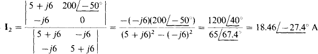
The Thevenin voltage can be found from I2, and I2 can be found from mesh analysis. The mesh equations are, from the self-impedance and mutual-impedance approach,

If Cramer’s rule is used to obtain I2, then
And

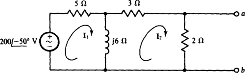
14.7 Find ZTh and IN for the Norton equivalent of the circuit shown in Fig. 14-9.
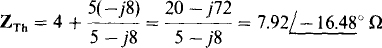
When the current source is replaced by an open circuit and the voltage source is replaced by a short circuit, the impedance at terminals a and b is
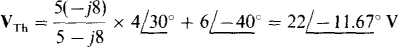
Because of the series arm connected to terminal a and the voltage source in it, the Norton current is best found from the Thévenin voltage and impedance. The Thévenin voltage is equal to the voltage drop
Fig. 14-9
across the parallel components plus the voltage of the voltage source:
And
14.8 Find ZTh and VTh for the Thévenin equivalent of the circuit shown in Fig. 14-10.
Fig. 14-10
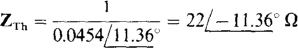
When the voltage source is replaced by a short circuit and the current source by an open circuit, the admittance at terminals a and b is

The inverse of this is ZTh
Because of the generally parallel configuration of the circuit, it may be better not to find VTh directly, but rather to obtain IN first and then find VTh from VTh = INZTh. If a short circuit is placed across terminals a and b, the short-circuit current is  since the short circuit prevents any current flow through the two parallel impedances. The current I can be found from the source voltage divided by the sum of the series impedances since the short circuit places this voltage across these impedances:
And so

Finally,

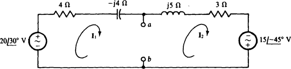
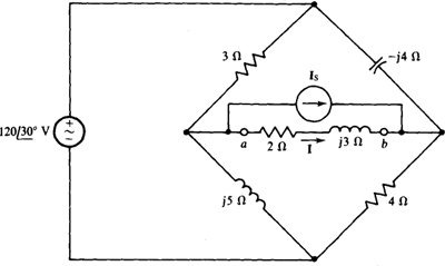
14.9 Using Thévenin’s or Norton’s theorem, find I in the bridge circuit shown in Fig. 14-11 if Is = 0 A.
Fig. 14-11
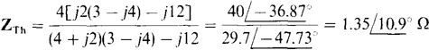
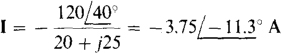
Since the current source produces 0 A, it is equivalent to an open circuit and can be removed from the circuit. Also, the 2-Ω and j3-Ω impedances need to be removed in finding an equivalent circuit because these are the load impedances. With this done, ZTh can be found after replacing the voltage source with a short circuit. This short circuit places the 3-Ω and j5-Ω impedances in parallel and also the — j4-Ω and 4-Ω impedances in parallel. Since these two parallel arrangements are in series between terminals a and b,

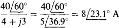
The open-circuit voltage is easier to find than the short-circuit current. By KVL applied at the bottom half of the bridge, VTh is equal to the difference in voltage drops across the j5- and 4-Ω impedances, which drops can be found by voltage division. Thus,
As should be evident from the Thévenin discussion and also from Fig. 14-lg, I is equal to the Thévenin voltage divided by the sum of the Thévenin and load impedances:
14.10 Find I for the circuit shown in Fig. 14-11 if IS=
The current source does not affect ZTh, which has the same value as found in the solution to Prob. 14.9:  . The current source does, however, contribute to the Thévenin voltage. By superposition, it contributes a voltage equal to the source current times the impedance at terminals a and b with the load replaced by an open circuit. Since this impedance is ZTh, the voltage contribution of the current source is
  , which is a voltage drop from terminal b to a because the direction of the source current is into terminal b. Consequently, the Thévenin voltage is, by superposition, the Thévenin voltage obtained in the solution to Prob. 14.9 minus this voltage:

and
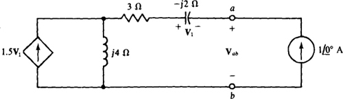
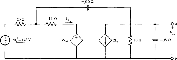
14.11 Find the output impedance of the circuit to the left of terminals a and b for the circuit shown in Fig. 14-12.
Fig. 14-12
The output impedance is the same as the Thévenin impedance. The only way of finding ZTh is by applying a source and finding the ratio of the voltage and current at the source terminals. This impedance cannot be found from ZTh = VTh/IN because VTh and IN are both zero since there are no independent sources to the left of terminals a and b. And, of course, circuit reduction cannot be used because of the presence of the dependent source. The most convenient source to apply is a  current source with a current direction into terminal a, as shown in Fig. 14-12. Then,
The first step in calculating ZTh is to find the control voltage V1. It is  with the initial negative sign occurring because the capacitor voltage and current references are not associated (The
  current is directed into the negative terminal of V1,). The next step is to find the current flowing down through the j4-Ω impedance. This is the current from the independent current source plus the 1.5V1 = 1.5(j2)=j3-A current from the dependent current source, a total of 1 +j3A. With this current known, the voltage Vab can be found from the sum of the voltage drops across the three impedances:

which, as mentioned, means that ZTh = — 9 +j2Ω The negative resistance (— 9 Ω) is the result of the action of the dependent source. In polar form this impedance is

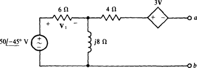
14.12 Find ZTh and IN for the Norton equivalent of the circuit shown in Fig. 14-13.
Fig. 14-13
Because of the series arm with dependent source connected to terminal a, VTh is easier to find than IN. This voltage is equal to the sum of the voltage drops across the j8Ω impedance and the 3V1 dependent voltage source. (Of course, the 4-Ω resistor has a 0-V drop.) It is usually best to first solve for the controlling quantity, which here is the voltage V1 across the 6-Ω resistor. By voltage division,
Since there is a 0-V drop across the 4-Ω resistor, KVL applied around the outside loop gives

The Thévenin impedance can be found by applying a current source of  at terminals a and b, as shown in the circuit in Fig. 14-14, and finding the voltage Vat. Then, ZTh = Vvb/1 = Vab. The control voltage V1, must be found first, as to be expected. It has a different value than in the VTh calculation because the circuit is different. The voltage V, can be found from the current I flowing through the 6-Ω resistor across which V1 is taken. Since the 6- and j8-Ω impedances are in parallel, and since from the current source flows into this parallel arrangement, I is, by current division,
Fig. 14-14
And, by Ohm’s law,

The negative sign is needed because the V1 and I references are not associated.
With V1 known, vab can be found by summing the voltage drops from terminal a to terminal b:

from which
Finally,
14.13 Find ZTh and IN for the Norton equivalent of the transistor circuit shown in Fig. 14.15.
Fig. 14-15
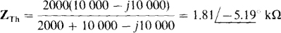
The Thévenin impedance ZTh can be found directly by replacing the independent voltage source by a short circuit. Since with this replacement there is no source of voltage in the base circuit, IB = 0 A and so the 50IB of the dependent current source is also 0 A. And this means that this dependent source is equivalent to an open circuit. Notice that the dependent source was not deactivated, as an independent source would be. Instead, it is equivalent to an open circuit because its control current is 0 A. With this current source replaced by an open circuit, ZTh can be found by combining impedances:
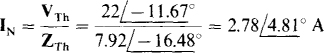
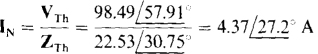
The current IN can be found from the current flowing through a short circuit placed across terminals a and b. Because this short circuit places the 10-kΩ and —j10-kΩ impedances in parallel, and since IN is the current through the — j10-kΩ impedance, then by current division IN is
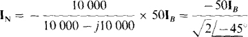
The initial negative sign is necessary because both 50IB and IN have directions into terminal b. The 2-kΩ resistance across terminals a and b does not appear because it is in parallel with the short circuit. From the base circuit,
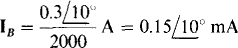
Finally,
14.14. Use PSpice to obtain the Thévenin equivalent of the circuit of Fig. 14-16.
Fig. 14-16
In general, using PSpice to obtain a Thévenin equivalent involves running PSpice twice to obtain two of the three quantities VTh, RTh, and IN. It does not matter, of course, which two are found.
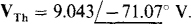
Figure 14-17 shows the corresponding PSpice circuit for determining the open-circuit voltage. Following is the circuit file along with the open-circuit voltage from the output file.
Fig. 14-17
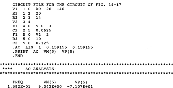
So,
Obtaining ZTh directly requires deactivating the independent voltage source, which in turn requires changing the node 1 specification of resistor Rl to node 0. Also, a current source of  A can be applied at the a-b terminals with the current directed into node a. Then, the voltage across this source has the same numerical value as ZTh. Following is the modified circuit file along with the source voltage from the output file.
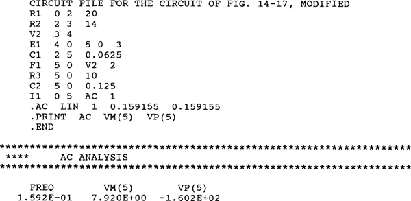
So,
14.15 What is the maximum average power that can be drawn from an ac generator that has an internal impedance of  and an rms open-circuit voltage of 12.5 kV? Do not be concerned about whether the generator power rating may be exceeded.
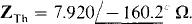
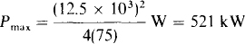
The maximum average power will be absorbed by a load that is the conjugate of the internal impedance, which is also the Thévenin impedance. The formula for this power is  12.5 kV and RTh = 150 cos 60° =75Ω So,
14.16 A signal generator operating at 2 MHz has an rms open-circuit voltage of 0.5 V and an internal impedance of 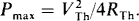 If it energizes a capacitor and parallel resistor, find the capacitance and resistance of these components for maximum average power absorption by this resistor. Also, find this power.
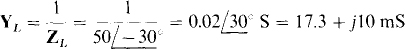
The load that absorbs maximum average power has an impedance Z, that is the conjugate of the internal impedance of the generator. So, 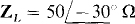 since the conjugate has the same magnitude and an angle that differs only in sign. Being in parallel, the load resistor and capacitor can best be determined from the load admittance, which is
But

So

and

The maximum average power absorbed by the 57.7-Ω resistor can be found from  in which RTh is the resistance of
Of course, 43.3 Ω is used instead of the 57.7 Ω of the load resistor because 43.3 Ω is the Thévenin resistance of the source as well as the resistance of the impedance of the parallel resistor-capacitor load.
14.17 For the circuit shown in Fig. 14-18, what load impedance ZL absorbs maximum average power, and what is this power?
Fig. 14-18
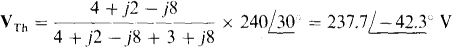
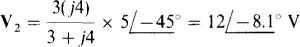
The Thévenin equivalent of the source circuit at the load terminals is needed. By voltage division,
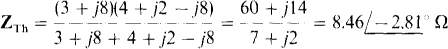
The Thévenin impedance is
For maximum average power absorption, 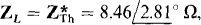 the resistive part of which is RTh 8.46 cos 2.81° = 8.45Ω Finally, the maximum average power absorbed is
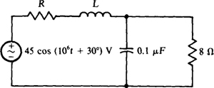
14.18 In the circuit shown in Fig. 14-19, find R and L for maximum average power absorption by the parallel resistor and capacitor load, and also find this power.
Fig. 14-19
A good first step is to find the load impedance. Since the impedance of the capacitor is
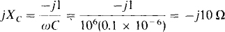
the impedance of the load is
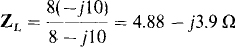
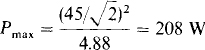
Since for maximum average power absorption there should be no reactance limiting the current to the resistive part of the load, the inductance L should be selected such that its inductive reactance cancels the capacitive reactance of the load. So, ωL = 3.9 Ω, from which L = 3.9/106 H = 3.9 μH. With the cancellation of the reactances, the circuit is essentially the voltage source, the resistance R, and the 4.88 Ω of the load, all in series. As should be apparent, for maximum average power absorption by the 4.88 Ω of the load, the source resistance should be zero: R = 0 Ω. Then, all the source voltage is across the 4.88 Ω and the power absorbed is
Notice that the source impedance is not the conjugate of the load impedance. The reason is that here the load resistance is fixed while the source resistance is a variable. The conjugate result occurs in the much more common situation in which the load impedance can be varied but the source impedance is fixed.
14.19 Use superposition to find V in the circuit shown in Fig. 14-20.
Fig. 14-20
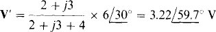
The voltage V can be considered to have a component V’ from the  source and another component V” from the
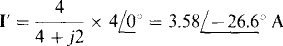
  source such that V = V– + V”. The component V– can be found by using voltage division after replacing the
  source with a short circuit:
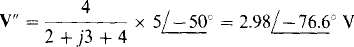
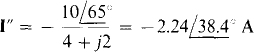
Similarly, V” can be found by using voltage division after replacing the source with a short circuit:
Adding,

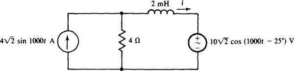
14.20 Use superposition to find i in the circuit shown in Fig. 14-21.
Fig. 14-21
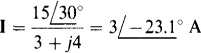
It is necessary to construct the corresponding phasor-domain circuit, as shown in Fig. 14-22. The current I can be considered to have a component I’ from the current source and a component I” from the voltage source such that I = I’ + I”. The component I’ can be found by using current division after replacing the voltage source with a short circuit:
Fig. 14-22
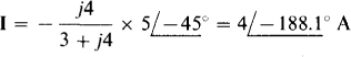
And I” can be found by using Ohm’s law after replacing the current source with an open circuit:
The negative sign is necessary because the voltage and current references are not associated. Adding,

Finally, the corresponding sinusoidal current is

14.21 Use superposition to find i for the circuit shown in Fig. 14-21 if the voltage of the voltage source is changed to 
The current i can be considered to have a component i– from the current source and a component i” from the voltage source. Because these two sources have different frequencies, two different phasor-domain circuits are necessary. The phasor-domain circuit for the current source is the same as that shown in Fig. 14-22, but with the voltage source replaced by a short circuit. As a result, the current phasor I’ is the same as that found in the solution to Prob. A. The corresponding current is

The phasor-domain circuit for the voltage source and ω = 2000 rad/s is shown in Fig. 14-23. By Ohm’s law.
Fig. 14-23
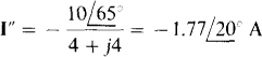
from which

Finally,

Notice in this solution that the phasors I’ and I” cannot be added, as they could be in the solution to Prob. 14-20. The reason is that here the phasors are for different frequencies, while in the solution to Prob. 14.20 they are for the same frequency. When the phasors are for different frequencies, the corresponding sinusoids must be found first, and then these added. Also, the sinusoids cannot be combined into a single term.
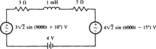
14.22 Although superposition does not usually apply to power calculations, it does apply to the calculation of average power absorbed when all sources are sinusoids of different frequencies. (A dc source can be considered to be a sinusoidal source of zero frequency.) Use this fact to find the average power absorbed by the 5-Ω. resistor in the circuit shown in Fig. 14-24.
Fig. 14-24
Consider first the dc component of average power absorbed by the 5-Q resistor. Of course, for this calculation the ac voltage sources are replaced by short circuits. Also, the inductor is replaced by a short circuit because an inductor is a short circuit to dc. So,
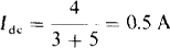
This 0.5-A current produces a power dissipation in the 5-Ω resistor of Pdc = 0.52(5) = 1.25 W. The rms current from the 6000-rad/s voltage source is, by superposition,

It produces a power dissipation of P6000 =0.42(5)=0.8w in the 5-Ω resistor. And the rms current from the 9000-rad/s voltage source is
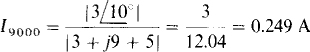
It produces a power dissipation of P9000 = 0.2492(5) = 0.31 W in the 5-Ω resistor.
The total average power Pav absorbed is the sum of these powers:

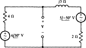
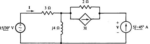
14.23 Use superposition to find V in the circuit shown in Fig. 14-25.
Fig. 14-25
If the independent current source is replaced by an open circuit, the circuit is as shown in Fig. 14-26, in which V is the component of V from the voltage source. Because of the open-circuited terminals, no part of I can flow through the 2-Ω resistor and the 31 dependent current source. Instead, all of I flows through the j4-Ω. impedance as well as through the 3-Ω resistance. Thus,
Fig. 14-26
With this I known, V’ can be found from the voltage drops across the 2- and j4-Ω impedances:

If the voltage source in the circuit of Fig. 14-25 is replaced by a short circuit, the circuit is as shown in Fig. 14-27, where V” is the component of V from the independent current source. As a reminder, the current to the left of the parallel resistor and dependent-source combination is shown as  , the same as the independent source current, as it must be. Because this current flows into the parallel 3-Ω and j4-Ω combination, the current I in the 3-Q resistor can be found by current division:
Fig. 14-27
With I known, V” can be found from the voltage drops Vi and V2 across the 2-Ω resistor and the parallel 3-Ω and j4-Ω impedances. Since the 2-Ω resistor current is 

Also, since the current in the 3-Ω and j4-Ω parallel combination is A,
So

Finally, by superposition,

The main purpose of this problem is to illustrate the fact that dependent sources are not deactivated in using superposition. Actually, using superposition on the circuit shown in Fig. 14-25 requires much more work than using loop or nodal analysis.
14.24 Transform the Δ shown in Fig. 14-28a to the Y in Fig. 14-28b for (a) Z1 = Z2 = Z3 = 
Fig. 14-28
(a) Because all three Δ impedances are the same, all three Y impedances are the same and each is equal to one-third of the common Δ impedance:
(b) All three Δ-to-Y transformation formulas have the same denominator, which is

By these formulas,
14.25 Transform the Y shown in Fig. 14-28b to the Δ in Fig. 14-28a for (a) ZA = ZB = ZC = 4 - j7 Ω, and (b) ZA = 10 Ω, ZB = 6 – j8 Ω2, and Zc = 
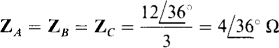
(a) Because all three Y impedances are the same, all three Δ impedances are the same and each is equal to three times the common Y impedance. So,

(b) All three Y-to-A transformation formulas have the same numerator, which here is

By these formulas,
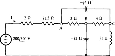
14.26 Using a Δ-to-Y transformation, find I for the circuit shown in Fig. 14-29.
Fig. 14-29
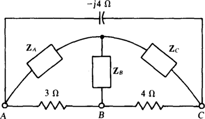
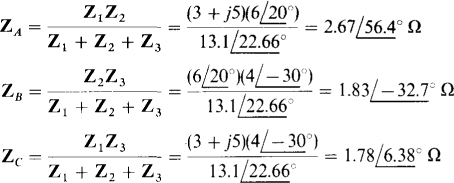
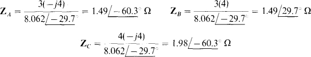
Extending between nodes A, B, and C there is a Δ, as shown in Fig. 14-30, that can be transformed to the shown Y, with the result that the entire circuit becomes series-parallel and so can be reduced by combining impedances. The denominator of each Δ-to-Y transformation formula is 3 + 4 — j4 — 1 — j4 = 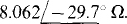 And by these formulas,
Fig. 14-30
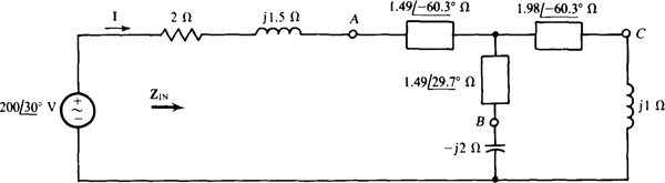
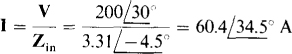
With this A-to-Y transformation, the circuit is as shown in Fig. 14-31. Since this circuit is in series-parallel form, the input impedance Zin can be found by circuit reduction. And then Zin can be divided into the
Fig. 14-31
applied voltage to get the current I:

Finally,
Incidentally, the circuit shown in Fig. 14-29 can also be reduced to series-parallel form by transforming the Δ of the -;2-, 4-, and jl-Ω impedances to a Y, or by transforming to a Δ either the Y of the 3-, -j2-, and 4-Ω impedances or that of the —j4-, 4-, and j l-Ω impedances.
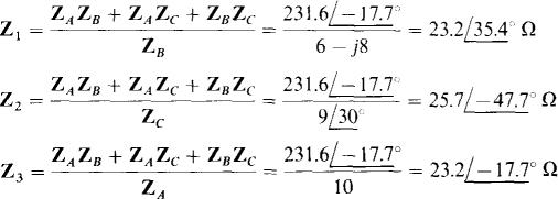
14.27 Find the current I for the circuit shown in Fig. 14-32.
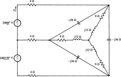
Fig. 14-32
As the circuit stands, a considerable number of mesh or nodal equations are required to find I. But the circuit, which has a Δ and a Y, can be reduced easily to just two meshes by using AΔ-Y transformations. Although these transformations do not always lessen the work required, they do here because they are so simple as a result of the common impedances of the Y branches and also of the Δ branches.
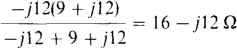
One way to reduce the Δ-Y configuration is shown in Fig. 14-33. If the Y of 9 + jl2-Ω impedances is transformed to a Δ, the result is a Δ of 3(9 +j’12) = 27 +J36-Ω impedances in parallel with the –j’36-Ω impedances of the original Δ, as shown in Fig. 14-33«. Combining the parallel impedances produces a Δ with impedances of
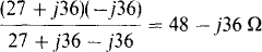
as shown in Fig. 14-33b. Then, if this is transformed to a Y, the Y has impedances of (48 –j36)/3 = 16 –j12 Ω, as shown in Fig. 14-33c.
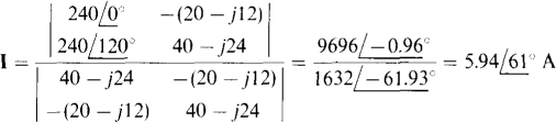
Figure 14-34 shows the circuit with this Y replacing the Δ-Y combination. The self-impedances of both meshes are the same: 4 + 16 – j12 – j12 + 16 + 4 = 40 –j24Ω, and the mutual impedance is 20 — 712 Ω. So, the mesh equations are
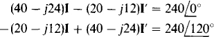
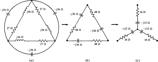
Fig. 14-33
By Cramer’s rule.
In reducing the Δ-Y circuit, it would have been easier to transform the Δ of —j36-Ω impedances to a Y of –j36/3 = –j12-Ω impedances. Then, although not obvious, the impedances of this Y would be in parallel with corresponding impedances of the other Y as a result of the two center nodes being at the same potential, which occurs because of equal impedance arms in each Y. If the parallel impedances are combined, the result is a Y of equal impedances of
the same as shown in Fig. 14-33r.
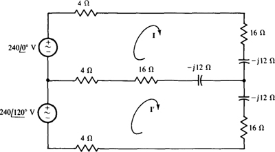
Fig. 14-34
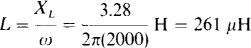
14.28 Assume that the bridge circuit of Fig. 14-3 is balanced for Zi = 5 Ω, 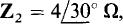 and Z3 = 8.2 Ω, and for a source frequency of 2 kHz. If branch Zx consists of two components in series, what are they?
The two components can be determined from the real and imaginary parts of Zx. From the bridge balance equation,
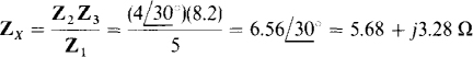
which corresponds to a 5.68-Ω resistor and a series inductor that has a reactance of 3.28 Ω. The corresponding inductance is
14.29 The bridge circuit shown in Fig. 14-35 is a capacitance comparison bridge that is used for measuring the capacitance Cx of a capacitor and any resistance Rx inherent to the capacitor or in series with it. The bridge has a standard capacitor, the capacitance Cs of which is known. Find Rx and Cx if the bridge is in balance for R1 = 500 Ω, R2 = 2 kΩ, R3 = 1 kΩ, Cs = 0.02 μF, and a source radian frequency of 1 krad/s.
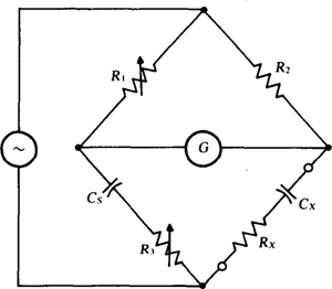
Fig. 14-35
The bridge balance equation can be used to determine Rx and Cx. From a comparison of Figs. 14-3 and 14-35, Z1 = 500 Ω Z2 = 2000 Ω,
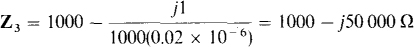
and

From the bridge balance equation Zx = Z2Z3/Z1,
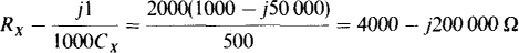
For two complex quantities in rectangular form to be equal, as here, both the real parts must be equal and the imaginary parts must be equal. This means that Rx = 4000 Ω and

14.30 For the capacitance comparison bridge shown in Fig. 14-35, derive general formulas for Rx and Cx in terms of the other bridge components.
For bridge balance, Z1Zx = Z2Z3, which in terms of the bridge components is

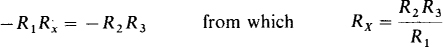
From equating real parts, R1Rx = R2R3, or Rx = R2R3/R1. And from equating imaginary parts, —R1/(ωCx) = —R2/(ωCs), or Cx = R1Cs/R2.
14.31 The bridge circuit shown in Fig. 14-36, called a Maxwell bridge, is used for measuring the inductance and resistance of a coil in terms of a capacitance standard. Find Lx and Rx if the bridge is in balance for R1 = 500kΩ, R2 = 6.2 kΩ, R3 = 5kΩ, and Cs = 0.1 μF.
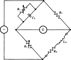
Fig. 14-36
First, general formulas will be derived for Rx and Lx in terms of the other bridge components. Then, values will be substituted into these formulas to find Rx and Lx for the specified bridge. From a comparison of Figs. 14-3 and 14-36, Z2 = R2, Z3 = R3, Zx = Rx + jωLx, and
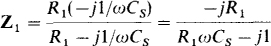
Substituting these into the bridge balance equation Z1Zx = Z2Z3 gives
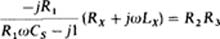
which, upon being multiplied by R1ωCs — j1 and simplified, becomes

From equating real parts,

and from equating imaginary parts,
which are the general formulas for Lx and Rx. For the values of the specified bridge, these formulas give

14.32 Find VTh and ZTh for the Thévenin equivalent of the circuit shown in Fig. 14-37.
Ans. 
14.33 What resistor will draw an 8-A rms current when connected across terminals a and b of the circuit shown in Fig. 14-37?
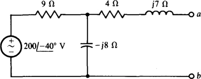
Fig. 14-37
Ans. 8.44 Ω
14.34 Find IN and ZTh for the Norton equivalent of the circuit shown in Fig. 14-38.
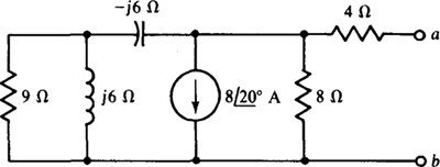
Fig. 14-38
Ans. 
14.35 Find VTh and ZTh for the Thévenin equivalent of the circuit shown in Fig. 14-39 for R = 0 Ω.

Fig. 14-39
Ans. 
14.36 Find IN and ZTh for the Norton equivalent of the circuit shown in Fig. 14-39 for R = 2 Ω
Ans. 
14.37 Find VTh and ZTh for the Thévenin equivalent of the circuit shown in Fig. 14-40 for R1 = R2 = 0Ω and Vs = 0 V.
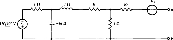
Fig. 14-40
Ans. 
14.38 Find VTh and ZTh for the Thévenin equivalent of the circuit shown in Fig. 14-40 for R1 = 5 Ω, R2 4 Ω, and 
Ans. 
14.39 Find VTh and ZTh for the Thévenin equivalent of the circuit shown in Fig. 14-41.
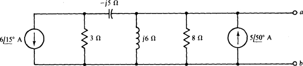
Fig. 14-41
Ans. 
14.40 What resistor will draw a 2-A rms current when connected across terminals a and b of the circuit shown in Fig. 14-41?
Ans. 1.21 Ω
14.41 Using Thévenin’s or Norton’s theorem, find 1 for the bridge circuit shown in Fig. 14-42 if Is = 0 A and ZL = 60∠30° Ω.
Ans. 
14.42 Find I for the bridge circuit shown in Fig. 14-42 if  and
and 
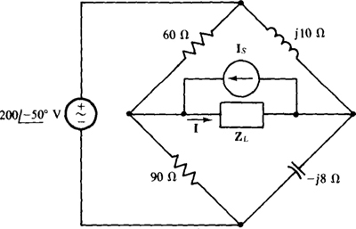
Fig. 14-42
Ans. 
14.43 Find the output impedance of the circuit shown in Fig. 14-43.
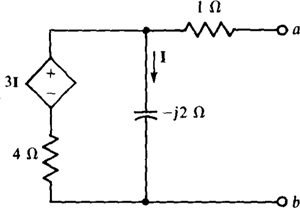
Fig. 14-43
Ans. 
14.44 Find the output impedance of the circuit shown in Fig. 14-43 with the I reference direction reversed--being up instead of down.
Ans. 
14.45 Find VTh and ZTh for the Thévenin equivalent of the circuit shown in Fig. 14-44.

Fig. 14-44
Ans. 
14.46 In the circuit shown in Fig. 14-44, reverse the I reference direction—have it up instead of down—and find IN and ZTh for the Norton equivalent circuit.
Ans. 
14.47 Find the output impedance at 104 rad/s of the circuit shown in Fig. 14-45.
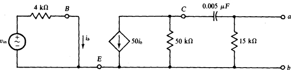
Fig. 14-45
Ans. 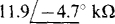
14.48 Use PSpice to obtain the Thévenin equivalent at the a and b terminals of the phasor-domain circuit corresponding to the time-domain circuit of Fig. 14-46.
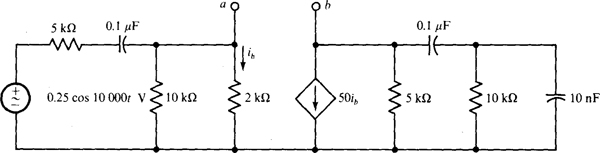
Fig. 14-46
Ans. 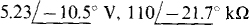
14.49 What is the maximum average power that can be drawn from an ac generator that has an internal impedance of  and an open-circuit voltage of 25 kV rms?
Ans. 1.66 MW
14.50 A signal generator operating at 5 MHz has an rms short-circuit current of 100 mA and an internal impedance of  . Ω If it energizes a capacitor and a parallel resistor, find the capacitance and resistance for maximum average power absorption by the resistor. Also, find this power.
Ans. 136 pF, 85.1 Ω, 0.213 W
14.51 For the circuit shown in Fig. 14-47, what ZL draws maximum average power and what is this power?
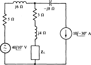
Fig. 14-47
Ans. 
14.52 In the circuit shown in Fig. 14-47, move the —j8-Ω. impedance from in series with the current source to in parallel with it. Find the ZL that absorbs maximum average power and find this power.
Ans. 
14.53 Use superposition to find I for the circuit shown in Fig. 14-48.
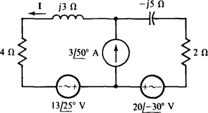
Fig. 14-48
Ans. 
14.54 For the circuit shown in Fig. 14-49, find the average power dissipated in the 3-Ω resistor using superposition and then without using superposition. Repeat this with the 10° phase angle changed to 40° for the one voltage source. (This problem illustrates the fact that superposition can be used to find the average power absorbed by a resistor from two sources of the same frequency only if these sources produce resistor currents that have a 90° difference in phase angle.)
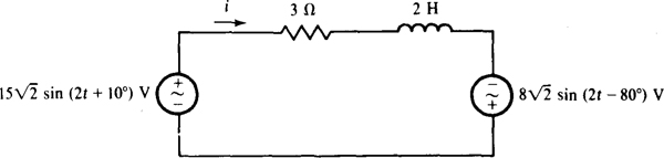
Fig. 14-49
Ans. 34.7 W using superposition and without using superposition; an incorrect 34.7 W with superposition and a correct 20.3 W without using superposition
14.55 Find v for the circuit shown in Fig. 14-50.
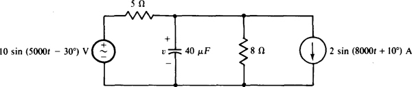
Fig. 14-50
Ans. 5.24 sin (5000t — 61.6°) — 4.39 sin (8000t — 34.6°) V
14.56 Find the average power dissipated in the 5-Q resistor of the circuit shown in Fig. 14-50.
Ans. 5.74 W
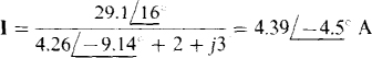
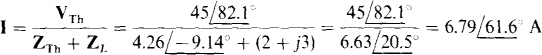
14.57 Find i for the circuit shown in Fig. 14-51.
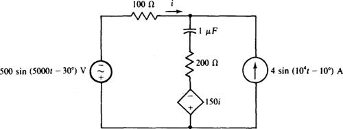
Fig. 14-51
Ans. —2 sin (5000t + 23.1°) — 4.96 sin (104t — 2.87°) A
14.58 Find the average power absorbed by the 200-Ω resistor in the circuit shown in Fig. 14-51.
Ans. 523 W
14.59 Transform the T shown in Fig. 14-52a to the Π in Fig. 14-52b for (a) 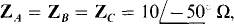 and (b)
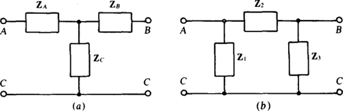
Fig. 14-52
Ans. (a) 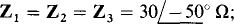 (b)
(b) 
14.60 Transform the Π shown in Fig. 14-52b to the T in Fig. 14-52a for (a) 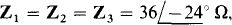 and (b)
Ans. (a) 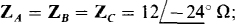 (b)
(b) 
14.61 Using a Δ-Y transformation, find I for the circuit shown in Fig. 14-53.
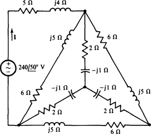
Fig. 14-53
Ans. 
14.62 Using a Δ-Y transformation, find I for the circuit shown in Fig. 14-54.
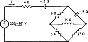
Fig. 14-54
Ans. 
14.63 Assume that the bridge circuit shown in Fig. 14-3 is balanced for  and Z3 = 9.1 Ω, and for a source frequency of 5 kHz. If branch Zx consists of two components in parallel, what are they?
Ans. A 39.9-Ω resistor and a 462-μH inductor
14.64 Find Cx and Rx for the capacitor comparison bridge shown in Fig. 14-35 if this bridge is balanced for R1 = 1 kΩ, R2 = 4 kΩ, R3 = 2 kΩ, and Cs = 0.1 μF.
Ans. 25 nF, 8 kΩ
14.65 Find Lx and Rx for the Maxwell bridge shown in Fig. 14-36 if this bridge is balanced for R1 = 50 kΩ, R2 = 8.2 kΩ, R3 = 4 kΩ, and Cs = 0.05 μF.
Ans. 1.64 H, 656 Ω