Chapter 1
Localized Chemical Bonding
Localized chemical bonding may be defined as bonding in which the electrons are shared by two and only two nuclei. Such bonding is the essential feature associated with the structure of organic molecules.1 Chapter 2 will discuss delocalized bonding, in which electrons are shared by more than two nuclei.
1.A. Covalent Bonding2
Wave mechanics is based on the fundamental principle that electrons behave as waves (e.g., they can be diffracted). Consequently, a wave equation can be written for electrons, in the same sense that light waves, sound waves, and so on, can be described by wave equations. The equation that serves as a mathematical model for electrons is known as the Schrödinger equation, which for a one-electron system is

where m is the mass of the electron, E is its total energy, V is its potential energy, and h is Planck's constant. In physical terms, the function (Ψ) expresses the square root of the probability of finding the electron at any position defined by the coordinates x, y, and z, where the origin is at the nucleus. For systems containing more than one electron, the equation is similar, but more complicated.
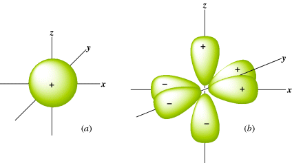
The Schrödinger equation is a differential equation, so solutions to it are themselves equations, but the solutions are not differential equations. They are just simple equations for which graphs can be drawn. Such graphs are essentially three-dimensional (3D) pictures that show the electron density, and these pictures are called orbitals or electron clouds. Most students are familiar with the shapes of the s and p atomic orbitals (Fig. 1.1). Note that each p orbital has a node: A region in space where the probability of finding the electron is extremely small.3 Also note that in Fig. 1.1 some lobes of the orbitals are labeled + and others −. These signs do not refer to positive or negative charges, since both lobes of an electron cloud must be negatively charged. They are the signs of the wave function Ψ. When a node separates two parts of an orbital, a point of zero electron density, Ψ always has opposite signs on the two sides of the node. According to the Pauli exclusion principle, no more than two electrons can be present in any orbital, and they must have opposite spins.
Fig. 1.1 (a) The 1s orbital. (b) The three 2p orbitals.
Unfortunately, the Schrödinger equation can be solved exactly only for one-electron systems (e.g., the hydrogen atom). If it could be solved exactly for molecules containing two or more electrons,4 a precise picture of the shape of the orbitals available to each electron (especially for the important ground state) would become available, as well as the energy for each orbital. Since exact solutions are not available, drastic approximations must be made. There are two chief general methods of approximation: the molecular orbital (MO) method and the valence bond method.
In the MO method, bonding is considered to arise from the overlap of atomic orbitals. When any number of atomic orbitals overlap, they combine to form an equal number of new orbitals, called molecular orbitals. Molecular orbitals differ from atomic orbitals in that an electron cloud effectively surrounds the nuclei of two or more atoms, rather than just one atom. In other words, the electrons are shared by two atoms rather than being localized on one atom. In localized bonding for a single covalent bond, the number of atomic orbitals that overlap is two (each containing one electron), so that two molecular orbitals are generated. One of these, called a bonding orbital, has a lower energy than the original atomic orbitals (otherwise a bond would not form), and the other, called an antibonding orbital, has a higher energy. Orbitals of lower energy fill first. Since the two original atomic orbitals each held one electron, both of these electrons will reside in the new molecular bonding orbital, which is lower in energy. Remember that any orbital can hold two electrons. The higher energy antibonding orbital remains empty in the ground state.
The strength of a bond is determined by the amount of electron density that resides between the two nuclei. The greater the overlap of the orbitals, the stronger the bond, but total overlap is prevented by repulsion between the nuclei. Figure 1.2 shows the bonding and antibonding orbitals that arise by the overlap of two 1s electrons. Note that since the antibonding orbital has a node between the nuclei, there is practically no electron density in that area, so that this orbital cannot be expected to bond very well. When the centers of electron density are on the axis common to the two nuclei, the molecular orbitals formed by the overlap of two atomic orbitals are called σ (sigma) orbitals, and the bonds are called σ bonds. The corresponding antibonding orbitals are designated σ∗. Sigma orbitals may be formed by the overlap of any of the atomic orbital (s, p, d, or f) whether the same or different, not only by the overlap of two s orbitals. However, the two lobes that overlap must have the same sign: A positive s orbital can form a bond only by overlapping with another positive s orbital or with a positive lobe of a p, d, or f orbital. Any σ molecular orbital may be represented as approximately ellipsoidal in shape.
Fig. 1.2 Overlap of two 1s orbitals gives rise to a σ and a σ∗ orbital.
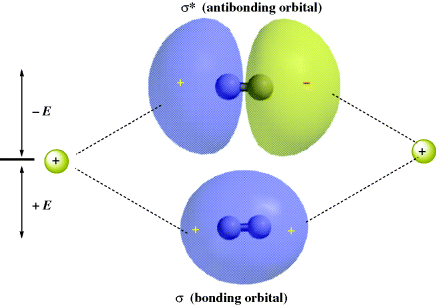
Orbitals are frequently designated by their symmetry properties. The σ orbital of hydrogen is often written ψg. The g stands for gerade. A gerade orbital is one in which the sign on the orbital does not change when it is inverted through its center of symmetry. The σ∗ orbital is ungerade (designated ψu). An ungerade orbital changes sign when inverted through its center of symmetry.
In MO calculations, the linear combination of atomic orbitals (known as LCAO) generates a wave function from a linear combination of overlapped atomic orbitals. Addition of the atomic orbitals gives the bonding MO:
The functions ψA and ψB are the functions for the atomic orbitals of atoms A and B, respectively, and cA and cB represent weighting factors. Subtraction is also a linear combination:
(1-2) 
This gives rise to the antibonding molecular orbital.
In the valence bond method, a wave equation is written for each of various possible electronic structures that a molecule may have (each of these is called a canonical form), and the total ψ is obtained by summation of as many of these as seem plausible, each with its weighting factor:
This resembles Eq. (1-1), but here each ψ represents a wave equation for an imaginary canonical form and each c is the amount contributed to the total picture by that form. For example, a wave function can be written for each of the following canonical forms of the hydrogen molecule5:

Values for c in each method are obtained by solving the equation for various values of each c, and choosing the solution of lowest energy. In practice, both methods give similar solutions for molecules that contain only localized electrons, and these are in agreement with the Lewis structures long familiar to the organic chemist. Delocalized systems are considered in Chapter 2. Note that orbital functions can indeed be reconstructed from measured data using several different approaches. Often, however, the results are still less accurate than those achieved with purely theoretical methods.6
1.B. Multiple Valence
A univalent atom has only one orbital available for bonding. But atoms with a valence of 2 or more must form bonds by using at least two orbitals. An oxygen atom has two half-filled orbitals, giving it a valence of 2. It forms single bonds by the overlap of these with the orbitals of two other atoms. According to the principle of maximum overlap, the other two nuclei should form an angle of 90° with the oxygen nucleus, since the two available orbitals on oxygen are p orbitals, which are perpendicular. If this is correct, nitrogen, which has three mutually perpendicular p orbitals, would have bond angles of 90° when it forms three single bonds. However, these are not the observed bond angles. The bond angles in water are,7 104°27′, and in ammonia, 106°46′. For alcohols and ethers, the angles are even larger (see Sec. 1.K). A discussion of this will be deferred to Section 1.K, but it is important to note that covalent compounds do have definite bond angles. Although the atoms are continuously vibrating, the mean position is the same for each molecule of a given compound.
1.C. Hybridization
Consider the case of mercury. Its electronic structure is

Although it has no half-filled orbitals, it has a valence of 2 and forms two covalent bonds. This result can be explained by imagining that one of the 6s electrons is promoted to a vacant 6p orbital to give the excited configuration

In this state, the atom has two half-filled orbitals, but they are not equivalent. If bonding were to occur by the overlap of these orbitals with the orbitals of external atoms, the two bonds would not be equivalent. The bond formed from the 6p orbital would be more stable than the one formed from the 6s orbital, since a larger amount of overlap is possible with the former. A more stable situation is achieved when, in the course of bond formation, the 6s and 6p orbitals combine to form two new orbitals that are equivalent; these are shown in Fig. 1.3.
Fig. 1.3 The two sp orbitals formed by mercury.
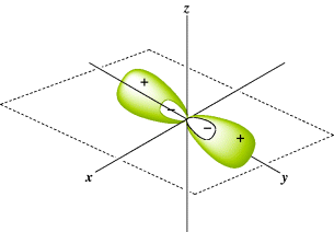
The new molecular orbitals are a mixture of the two original orbitals, so they are called hybrid orbitals. Each orbital is a merger of an s and p orbital and is called an sp orbital. The sp orbitals, each of which consists of a large lobe and a very small one, arise only in the bonding process and do not represent a possible structure for the free atom. A mercury atom forms its two bonds by overlapping each of the large lobes shown in Fig. 1.3 with an orbital from an external atom. The orbital of this external atom may be any of the atomic orbitals previously considered (s, p, d, or f), or it may be another hybrid orbital. Note that only lobes of the same sign can overlap. In any of these cases, the molecular orbital that arises is called a σ orbital since it fits the previous definition of a σ orbital.
In general, equivalent orbitals lie as far away from each other as possible because of mutual repulsion, so two sp orbitals form an angle of 180°. In other words, an atom that forms only two σ bonds uses two sp orbitals so HgCl2, for example, should be a linear molecule, and it is. This kind of hybridization is called digonal hybridization. An sp hybrid orbital forms a stronger covalent bond than either an s or a p orbital because it extends out in space in the direction of the other atom's orbital farther than the s or the p and permits greater overlap. Compare HgCl2 with water (OH2). It is known that the shape of HgCl2 is linear, but water is angular. This fact suggests that the hybrid orbitals utilized by oxygen in water is different from those used by mercury in HgCl2.
Many other kinds of hybridization are possible. Consider boron, which has the electronic configuration 1s22s22p1 yet has a valence of 3. To begin, boron has only three valence electrons available to form bonds, hence the valence of three. Any hybridization model must take this into account. As before, imagine promotion of an electron and hybridization:

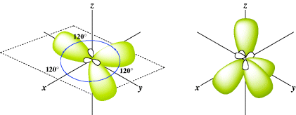
In this case, there are three equivalent hybrid orbitals, each called sp2 (trigonal hybridization). This method of designating hybrid orbitals is perhaps unfortunate since nonhybrid orbitals are designated by single letters, but keep in mind that each of the three orbitals is called sp2. The key is to understand that the atom forms two σ bonds for sp hybridization and three σ bonds for sp2 hybridization. The sp2 hybrid orbitals just noted are shown in Fig. 1.4. The three axes are all in one plane and point to the corners of an equilateral triangle. This accords with the known structure of BF3, a planar molecule with angles of 120°.
Fig. 1.4 The three sp2 and the four sp3 orbitals.
Another type of hybrid orbital is possible, formed by atoms that can form four σ bonds. Carbon is an important atom that can form four single bonds (four σ bonds). Imagine promotion of an electron and hybridization that leads to

There are four equivalent molecular orbitals, each called sp3, and electron repulsion leads to a shape in which the orbitals point to the corners of a regular tetrahedron (Fig. 1.4). A typical molecule is methane (CH4) and assuming that carbon forms four bonds with sp3 hybrid orbitals, the bond angles of methane would thus be expected to be 109°28′, which is the angle for a regular tetrahedron. In reality, electrons are not “promoted” in atomic orbitals, but atomic orbitals are different from molecular orbitals (e.g., those found in methane). The model of promoting an electron is a mathematical device to describe molecular orbitals using the atomic orbitals.
The hybrid orbitals discussed in this section stem from only one possible approximate solution of the Schrödinger equation. The s and the three p atomic orbitals used to form sp3 orbitals, for example, can be combined in other equally valid ways. As will be seen in Section 1.E, the four C–H bonds of methane do not always behave as if they are equivalent. Bickelhaupt6 has proposed an alternative approach to the bonding in carbon suggesting that the maximum coordination number of carbn cannot exceed four because it is too small to allow more than four substituents approach and form the appropriate bonds.
1.D. Multiple Bonds
If ethylene (H2C=CH2) is examined in terms of the MO concepts discussed so far, each carbon has three σ bonds, one to each of the three atoms. Therefore, sp2 orbitals are used to form those three bonds. These sp2 orbitals arise from hybridization of the 2s1, 2px1, and 2py1 electrons after promotion of electrons (Sec. 1.C). In general, any carbon atom that is bonded to only three different atoms uses sp2 orbitals for this bonding. The three σ bonds of ethylene are one to each of two hydrogen atoms and one to the other carbon. Each carbon therefore has another electron in the 2pz orbital that is perpendicular to the plane of the sp2 orbitals. The two parallel 2pz orbitals, one on each of the two adjacent carbon atoms, can overlap sideways to generate a bonding and an antibonding orbital (Fig. 1.5). In the ground state, both electrons go into the bonding orbital and the antibonding orbital remains vacant. In other words, a new bond is formed, but it is formed by sideways overlap of adjacent p orbitals rather than direct overlap of σ orbitals. Molecular orbitals formed by the overlap of atomic orbitals whose axes are parallel are called π orbitals if they are bonding and π∗ if they are antibonding.
Fig. 1.5 (a) Overlapping p orbitals form a π and a π∗ orbital. The σ orbitals are shown in (a). The π orbitals are shown in (b) as the highest occupied molecular orbital (HOMO) (on the left) and the LUMO. In (c), the electron potential map of ethylene shows the concentration of electron density above and below the plane of the atoms, consistent with a π bond.
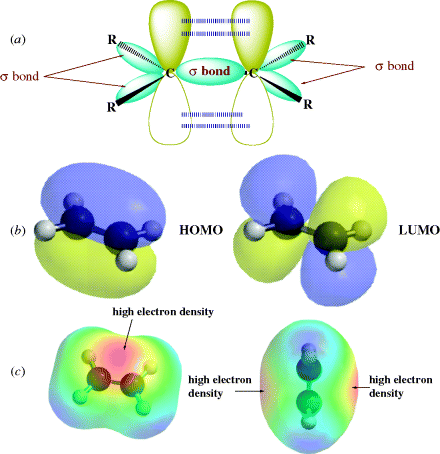
In this picture of ethylene, there are two bonds connecting the adjacent carbon atoms, but the two orbitals that make up the double bond are not equivalent.8 This means that the two bonds are different one from the other. The σ orbital is ellipsoidal and symmetrical about the C–C axis, and this is the familiar σ bond. The π orbital is in the shape of two ellipsoids, one above the plane and one below, and forms the second bond, a π bond. The plane itself represents a node for the π orbital. In order for the p orbitals to maintain maximum overlap, they must be parallel. Since both a σ bond and the π bond connect the two carbon atoms, free rotation is not possible about the double bond. In other words, the two p orbitals would have to reduce their overlap to allow one H–C–H plane to rotate with respect to the other (i.e., the π bond would have to disappear). With two sp2 hybrid carbon atoms in ethylene, the six atoms associated with the double bond (H2C=CH2) are in a plane with angles that should be ~120°. Double bonds are shorter than the corresponding single bonds because maximum stability is obtained when the p orbitals overlap as much as possible (see Sec. 1.J). Double bonds between carbon and oxygen (C=O) or nitrogen (C=N) similarly consist of one σ and one π orbital.
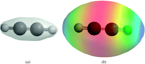
When carbon is connected to another carbon atom by a triple bond, as in acetylene (HC CH), each carbon is connected to only two other atoms by a σ bond, and hence uses sp hybridization. This fact requires that the four atoms of acetylene (2H and 2C) are in a straight line (Fig. 1.6).9 Each carbon has two p orbitals remaining, with one electron in each. These orbitals are perpendicular to each other and also to the C–C axis. They overlap in the manner shown in Fig. 1.7 to form two π orbitals. A triple bond is thus composed of one σ and two π orbitals. Triple bonds between carbon and nitrogen can be represented in a similar manner, C
 N.
N.
Fig. 1.6 The σ orbitals of acetylene.

Fig. 1.7 (a) The electron density map of acetylene. Note the concentration of electron density along a line between the nuclei of each atom, consistent with overlap of σ orbitals in a triple bond. (b) Electron potential map of acetylene showing the concentration of electron density between the carbon atoms, consistent with two orthogonal π bonds.
For most organic molecules, double and triple bonds typically involve the first-row elements carbon, nitrogen, and oxygen.10 Second-row elements tend to form weaker π bonds than do the first-row elements,11 so multiple bonds are less common and compounds containing them are generally less stable.12 Compounds with C=S bonds are known, for example, and C=S compounds are generally much less stable than the corresponding C=O compounds (however, see pπ–dπ bonding in Sec. 2.H). Stable compounds with Si=C and Si=Si bonds are rare, but examples have been reported,13 including a pair of cis and trans Si=Si isomers.14
There is at least one report of a so-called two-electron, four-center C–C bond for the dimer of tetracyanoethylene.15 While such multi-center bonding is not formally an example of the multiple bonding described in this section, it constitutes a different type of bonding when compared to the simple C–C bonds described earlier.
1.E. Photoelectron Spectroscopy
Based on the hybridization model, methane is expected to have four equivalent σ bonds. Indeed, the four bonds of methane are equivalent according to most physical and chemical methods of detection. The nuclear magnetic resonance (NMR) and the infrared (IR) spectrum of methane show no peaks that can be attributed to different kinds of C–H bonds. However, there is one physical technique showing that the eight valence electrons of methane can be differentiated. In this technique, called photoelectron spectroscopy (PES),16 a molecule or free atom is bombarded with vacuum ultraviolet (UV) radiation, causing an electron to be ejected. The energy of the ejected electron can be measured, and the difference between the energy of the radiation used and that of the ejected electron is the ionization potential of that electron. A molecule that contains several electrons of differing energies can lose any one of them as long as its ionization potential is less than the energy of the radiation used. A single molecule loses only one electron; the loss of two electrons by any individual molecule almost never occurs. Since electrons reside in orbitals, a photoelectron spectrum consists of a series of bands, each corresponding to an orbital of a different energy. The spectrum gives a direct experimental picture of all orbitals that are present, and they are ejected in ascending order of their energies, provided that radiation of sufficiently high energy is used.17 Broad bands usually correspond to strongly bonding electrons and narrow bands to weakly bonding or nonbonding electrons.
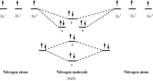
Using PES, it is possible to probe the validity of the hybridization model for bonding. Dinitrogen (N2) is a typical diatomic molecule and is shown in Fig. 1.8.18 The N2 molecule has the electronic structure shown in Fig. 1.9: The two 2s orbitals of the nitrogen atoms combine to give the two orbitals marked 1 (bonding) and 2 (antibonding), while the six 2p orbitals combine to give six orbitals, three of which (marked 3, 4, and 5) are bonding. The three antibonding orbitals (not indicated in Fig. 1.9) are unoccupied. Electrons ejected from orbital 1 are not found in Fig. 1.8 because the ionization potential of these electrons is greater than the energy of the light used (they can be seen when higher energy light is used). The broad band in Fig. 1.8 corresponds to the four electrons in the degenerate orbitals 3 and 4. The individual peaks within this band are caused by different vibrational levels (see Chap. 7). The triple bond of N2 is therefore composed of these two orbitals and orbital 1. The bands corresponding to orbitals 2 and 5 are narrow; hence these orbitals contribute little to the bonding and may be regarded as the two unshared pairs of  . Note that this result is contrary to that expected from a naive consideration of orbital overlaps, where it would be expected that the two unshared pairs would be those of orbitals 1 and 2, resulting from the overlap of the filled 2s orbitals. In addition, the triple bond would be composed of orbitals 3, 4, and 5, resulting from overlap of the p orbitals. This example is one illustration of the value of PES.
Fig. 1.8 Photoelectron spectrum of N2.18 [Reprinted with permission from Brundle, C.R.; Robin, M.B. in Nachod, F.C.; Zuckerman, J.J. Determination of Organic Structures by Physical Methods, Vol. 1, Academic Press, NY, 1971, p. 18. Copyright © 1971, with permission from Elsevier Science. With permission of C. Richard Brundle, 2012.]
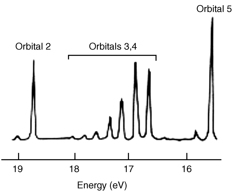
Fig. 1.9 Electronic structure of N2 (inner-shell electrons omitted).
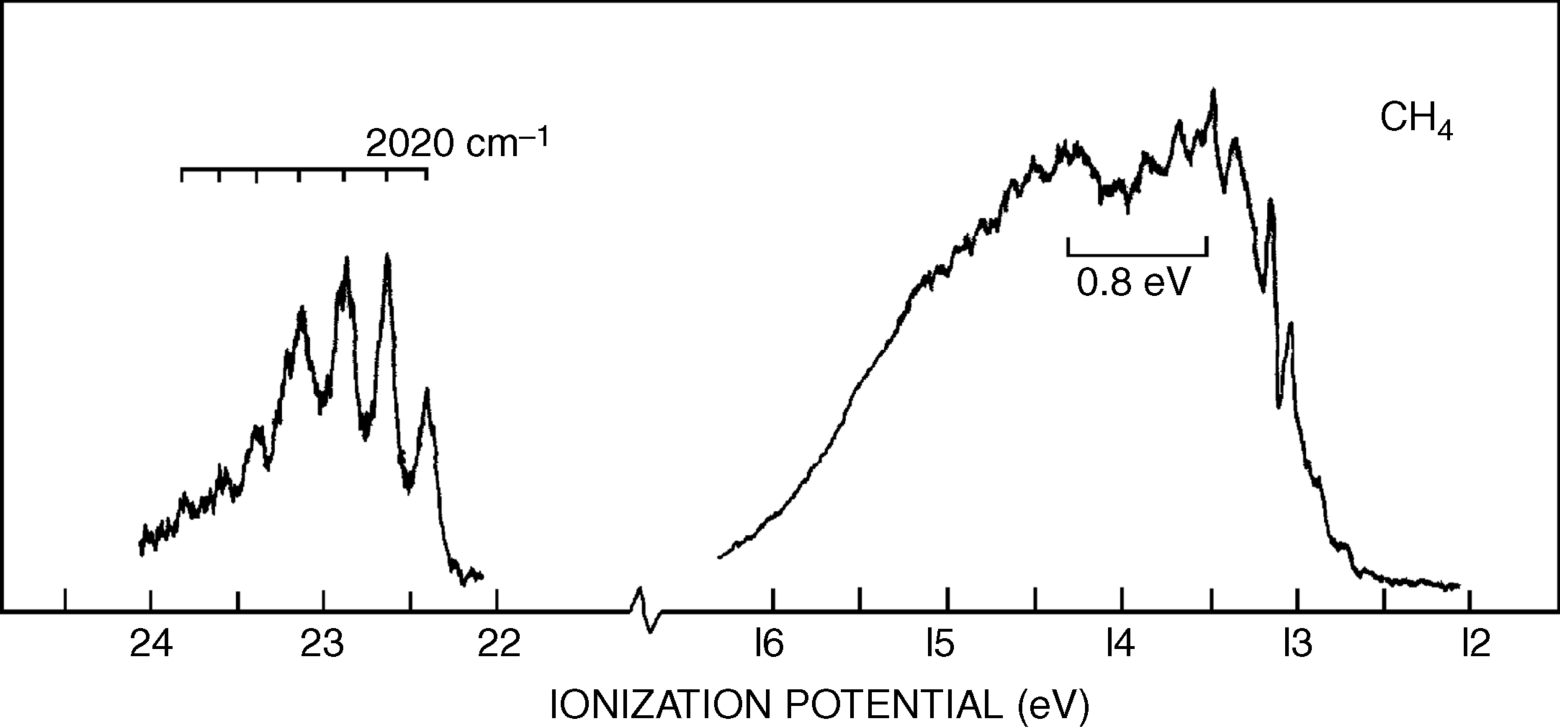
The photoelectron spectrum of methane19 in Fig. 1.10 shows two bands,20 at ~23 and 14 eV, and not the single band expected from the equivalency of the four C–H bonds. Indeed, Fig. 1.10 suggests that carbon uses the available orbitals to form four bonds and the electrons in the bonds are distributed between carbon and the four atoms involved in the bonds. Remember that the hybridization model predicts four identical σ bonds made by overlap of four identical hybrid orbitals. The band at 23 eV comes from two electrons in a low-energy level (called the a1 level), which can be regarded as arising from a combination of the 2s orbital of carbon with an appropriate combination of hydrogen 1s orbitals. The band at 14 eV comes from six electrons in a triply degenerate level (the t2 level), arising from a combination of the three 2p orbitals of carbon with other combinations of 1s hydrogen orbitals. As mentioned above, most physical and chemical processes cannot distinguish these levels, but PES can. The photoelectron spectra of many other organic molecules are known as well,21 including monocyclic alkenes, in which bands < 10 eV are due to π-orbital ionization and those >10 eV originate from ionization of σ orbitals only.22 Note that ordinary sp3 hybridization is not adequate to explain phenomena involving ionized molecules (e.g., the  radical ion, which is left behind when an electron is ejected from methane). For these phenomena, it is necessary to use other combinations of atomic orbitals (see Sec. 1.C).
Fig. 1.10 Photoelectron spectroscopy scan of methane. [Reprinted with permission from Brundle, C.R.; Robin, M.B. J. Chem. Phys. 1970 , 53, 2196. Copyright © 1970, American Institute of Physics.]
1.F. Electronic Structures of Molecules
For each molecule, ion, or free radical that has only localized electrons, it is possible to draw an electronic formula, called a Lewis structure, which shows the location of these electrons. Only the valence electrons are shown. Valence electrons may be found in covalent bonds connecting two atoms or they may be unshared.23 Drawing these structures correctly is essential, since the position of electrons changes in the course of a reaction, and it is necessary to know where the electrons are initially before one can follow where they are going. To this end, the following rules operate:
 , the number is also 32, since each atom “contributes” 6 plus 2 for the negative charge.
 : has a lower energy than
  :. Although first-row atoms are limited to 8 valence electrons, this is not so for second-row atoms, which can accommodate 10 or even 12 because empty d orbitals may be utilized.24 For example, PCl5 and SF6 are stable compounds, and the hybridization model can be used to explain this fact. In SF6, one s and one p electron from the ground state 3s23p4 of the sulfur are promoted to empty d orbitals, and the six orbitals hybridize to give six sp3d2 orbitals, which point to the corners of a regular octahedron.
Examples of electronic structures are

A coordinate-covalent bond (sometimes called a dative bond), represented by an arrow, is one in which both electrons come from the same atom; that is, the bond can be regarded as being formed by the overlap of an orbital containing two electrons with an empty one. Thus trimethylamine N-oxide would be represented:

For a coordinate-covalent bond, the rule concerning formal charge is amended so that both electrons count for the donor and neither for the recipient. Thus the nitrogen and oxygen atoms of trimethylamine oxide bear no formal charges. However, it is apparent that the electronic picture is exactly the same as the picture of trimethylamine N-oxide given just above, and there is a choice of drawing an arrowhead or a charge separation. Some compounds (e.g., amine N-oxides) must be drawn one way or the other. It is usually simpler to use charge separation.
1.G. Electronegativity
The electron cloud that bonds two atoms is not symmetrical (with respect to the plane that is the perpendicular bisector of the bond) except when the two atoms are the same and have the same substituents. A symmetrical electron cloud typically occurs when there is a bond between two identical atoms, and an unsymmetrical electron cloud occurs when there are two different atoms. When there are two different atoms, and one is more electronegative than the other, the electron cloud is necessarily distorted toward one side of the bond or the other, depending on which atom (nucleus plus electrons) maintains the greater attraction for the cloud. This attraction is called electronegativity;25 and it is greatest for atoms in the upper-right corner of the periodic table and lowest for atoms in the lower-left corner. Thus a bond between fluorine and carbon (C–F) shows distortion of the electron cloud associated with the bond, so that there is a higher probability of finding the electrons near the fluorine than near the carbon. Such a bond is said to be polarized, and the C–F bond is an example of a polarized covalent bond. The polarization gives the fluorine a partial negative charge (δ−) and the carbon a partial positive charge (δ+).
A number of attempts have been made to set up quantitative tables of electronegativity that will indicate the direction and extent of electron-cloud distortion for a bond between any pair of atoms. The most popular of these scales, devised by Pauling, is based on bond energies (see Sec. 1.L) of diatomic molecules. It is rationalized that if the electron distribution were symmetrical in a molecule A–B, the bond energy would be the mean of the energies of A–A and B–B, since in these cases the cloud must be undistorted. If the actual bond energy of A–B is higher than this (and it usually is), it is the result of the partial charges (the charges attract each other and make a stronger bond, which requires more energy to break). It is necessary to assign a value to one element arbitrarily (F = 4.0). Then the electronegativity of another is obtained from the difference between the actual energy of A–B and the mean of A–A and B–B (this difference is called Δ) by the formula

where xA and xB are the electronegativities of the known and unknown atoms and 23.06 is an arbitrary constant. Part of the scale derived from this treatment is shown in Table 1.1.26,27
Table 1.1 Electronegativities of Some Atoms on the Pauling26 and Sanderson27 Scales.

Other treatments28 have led to scales that are based on different principles, for example, the average of the ionization potential and the electron affinity,29 the average one-electron energy of valence-shell electrons in ground-state free atoms,30 or the “compactness” of an atom's electron cloud.24 In some of these treatments, electronegativities can be calculated for different valence states, for different hybridizations (e.g., sp carbon atoms are more electronegative than sp2, which are still more electronegative than sp3),31 and even differently for primary, secondary, and tertiary carbon atoms. Also, electronegativity values can be calculated for groups rather than atoms (Table 1.2).32
Table 1.2 Some Group Electronegativities Relative to H = 2.17632

Electronegativity information can be obtained from NMR spectra. In the absence of a magnetically anisotropic group33 the chemical shift of a  or a
or a  nucleus is approximately proportional to the electron density around it, and hence to the electronegativity of the atom or group to which it is attached. The greater the electronegativity of the atom or group, the lower the electron density around the proton, and the further downfield the chemical shift [relative to tetramethylsilane (TMS) as zero ppm]. An example of the use of this correlation is found in the variation of chemical shift of the ring protons in the series toluene, ethylbenzene, isopropylbenzene, and tert-butylbenzene (there is a magnetically anisotropic group here, but its effect should be constant throughout the series). The electron density surrounding the ring protons decreases34 in the order given.35 However, this type of correlation is by no means perfect, since all the measurements are made in a powerful field, which itself may affect the electron density distribution. Coupling constants between the two protons of a system –CH–CH–X have also been found to depend on the electronegativity of X.36
When the difference in electronegativities is great, the electron density in an orbital may be effectively localized on only one nucleus. This is an ionic bond, which is seen to arise naturally out of the previous discussion. It is possible to view polarized covalent bonds as intermediates between ionic and covalent bonds. With this view, the extent of electron-cloud distortion is expressed as the percent ionic character of a bond. In this model, there is a continuous gradation from ionic to covalent bonds.
1.H. Dipole Moment
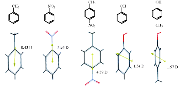
The dipole moment is a property of a molecule that results from charge separations like those discussed above. However, it is not possible to measure the dipole moment of an individual bond within a molecule. Only the total moment of the molecule may be measured, and it is the vectorial sum of the individual bond moments.37 These individual moments are roughly the same from molecule to molecule,38 but this constancy is by no means universal. Thus, from the dipole moments of toluene and nitrobenzene (Fig. 1.11)39 the moment of p-nitrotoluene is predicted to be ~4.36 D. The actual value 4.39 D is reasonable. However, the moment of p-cresol (1.57 D) is quite far from the predicted value of 1.11 D. In some cases, molecules may have substantial individual bond moments, but no total moments at all because the individual moments are canceled out by the overall symmetry of the molecule. Some examples are CCl4, trans-1,2-dibromoethene, and p-dinitrobenzene.
Fig. 1.11 Some dipole moments, in Debye units, measured in benzene. In the 3D model, the arrow indicates the direction of the dipole moment for the molecule, pointing to the negative part of the molecule.39
Because of the small difference between the electronegativities of carbon and hydrogen, alkanes have very small dipole moments, so small that they are difficult to measure. For example, the dipole moment of isobutane is 0.132 D40 and that of propane is 0.085 D.41 Of course, methane and ethane, because of their symmetry, have no dipole moments.42 Few organic molecules have dipole moments > 7 D.
1.I. Inductive and Field Effects
The C–C bond in ethane has no polarity because it connects two equivalent atoms, with identical electronegativities. The presence of a more electronegative atom attached to one of the carbon atoms will lead to bond polarization, however, in what is known as an induced dipole. The C–C bond in chloroethane, for example, is polarized by the presence of the electronegative chlorine atom. This polarization is actually the sum

of two effects. In the first of these, the C-1 atom is deprived of some of its electron density by the greater electronegativity of Cl, and this effect is partially compensated by drawing the C–C electrons closer to itself. The result is a polarization of this bond and a slightly positive charge on the C-2 atom: an induced dipole. This polarization of one bond caused by the polarization of an adjacent bond is known as an inductive effect. The effect is greatest for adjacent bonds but may also be felt farther away; thus the polarization of the C–C bond causes a (slight) polarization of the three methyl C–H bonds. As a practical matter, the effect is negligible if the polarizing group is more than three bonds away.
The other effect operates not through bonds, but directly through space or solvent molecules, and is called a field effect.43 It is often very difficult to separate the two kinds of effect, but a number of cases have been reported. This is generally accomplished by taking advantage of the fact that the field effect depends on the geometry of the molecule, but the inductive effect depends only on the nature of the bonds. For example, in isomers, 1 and 244 the inductive effect of the chlorine atoms on the position of the electrons in the COOH group (and hence on the

acidity, see Chap. 8) should be the same since the same bonds intervene. The field effect is different, however, because the chlorine atoms are closer in space to the COOH in 1 than they are in 2. Thus, a comparison of the acidity of 1 and 2 should reveal whether a field effect is truly operating. The evidence obtained from such experiments is overwhelming that field effects are much more important than inductive effects.45 In most cases, the two types of effect are considered together; in this book, they will not be separated but will use the name field effect to refer to their combined action.46 Note that the field effect for 1 may be viewed as internal hydrogen bonding (see Sec. 3.A).
Functional groups can be classified as electron withdrawing (−I) or electron donating (+I) groups relative to hydrogen. This means, for example, that NO2, a −I group, will draw electrons to itself more than a hydrogen atom would if it occupied the same position in the molecule.

Thus, in α-nitrotoluene, the electrons in the N–C bond are farther away from the carbon atom than the electrons in the H–C bond of toluene. Similarly, the electrons of the C–Ph bond are farther away from the ring in α-nitrotoluene than they are in toluene. Field effects are always comparison effects. For example, compare the −I or +I effect of one group with another (usually hydrogen). Therefore, it may be said that, compared with hydrogen, the NO2 group is electron withdrawing and the O− group is electron donating or electron releasing. However, there is no actual donation or withdrawal of electrons, but rather electron distortion or electron redistribution. While withdrawing and releasing terms are convenient to use, the terms merely represent a difference in the position of electrons due to the difference in electronegativity between H and NO2 or between H and O−.
Table 1.3 lists a number of the most common −I and +I groups.47 It can be seen that compared with hydrogen, most groups are electron withdrawing. The only electron-donating groups are those with a formal negative charge (but not even all these), atoms of low electronegativity (Si,48 Mg, etc., and perhaps alkyl groups). Alkyl groups49 were formerly regarded as electron donating, but many examples of behavior have been found that can be interpreted only by the conclusion that alkyl groups are electron withdrawing compared with hydrogen.50 In accord with this is the value of 2.472 for the group electronegativity of CH3 (Table 1.2) compared with 2.176 for H. When an alkyl group is attached to an unsaturated or trivalent carbon (or other atom), its behavior is best explained by assuming it is +I (see, e.g., Sec. 5.A.ii, 5.B.i, 8.E, 11.B.i), but when it is connected to a saturated atom, the results are not as clear, and alkyl groups seem to be +I in some cases and −I in others51 (see also, Sec. 8.F). When connected to a positive carbon, alkyl groups are clearly electron releasing.
Table 1.3 Field Effects of Various Groups Relative to Hydrogena

aThe groups are listed approximately in order of decreasing strength for both −I and +I groups. [Reprinted with permission from Ceppi, E.; Eckhardt, W.; Grob, C.A. Tetrahedron Lett. 1973, 3627. Copyright © 1973, with permission from Elsevier Science.]
It is clear that the field-effect order of alkyl groups attached to unsaturated systems is tertiary > secondary > primary > CH3, but this order is not always maintained when the groups are attached to saturated systems. Deuterium is electron donating with respect to hydrogen.52 Other things being equal, atoms with sp bonding generally have a greater electron-withdrawing power than those with sp2 bonding, which in turn have more electron-withdrawing power than those with sp3 bonding.53 This accounts for the fact that aryl, vinylic, and alkynyl groups are −I. Field effects always decrease with increasing distance, and in most cases (except when a very powerful +I or −I group is involved), cause very little difference in a bond four bonds away or more. There is evidence that field effects can be affected by the solvent.54
For discussions of field effects on acid and base strength and on reactivity, see Chapters 8 and 9, respectively.
1.J. Bond Distances55
The distances between atoms in a molecule are characteristic properties of the molecule and can give information if compared with the same bond in different molecules. The chief methods of determining bond distances and angles are X-ray diffraction (only for solids), electron diffraction (only for gases), and spectroscopic methods, especially microwave spectroscopy. The distance between the atoms of a bond is not constant, since the molecule is always vibrating; the measurements obtained are therefore average values, so that different methods give different results.56 However, this must be taken into account only when fine distinctions are made.
Measurements vary in accuracy, but indications are that similar bonds have fairly constant lengths from one molecule to the next. While exceptions are known,57 the variation is generally < 1%. Table 1.4 shows distances for single bonds between two sp3 carbons.58–65 However, an analysis of C–OR bond distances in >2000 ethers and carboxylic esters (all with sp3 carbon) shows that this distance increases with increasing electron withdrawal in the R group and as the C changes from primary to secondary to tertiary.66 For these compounds, mean bond lengths of the various types ranged from 1.418 to 1.475 Å. Certain substituents can also influence bond length. The presence of a silyl substituent β− to a C–O (ester) linkage can lengthen the C–O, thereby weakening it.67 This finding is believed to result from σ–σ∗ interactions in which the C–Si σ bonding orbital acts as the donor and the C–O σ∗ orbitals acts as the receptor.
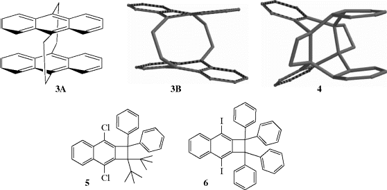
Table 1.4 Bond Lengths between sp3 Carbons in Some Compounds.
| C–C Bond in | Reference | Bond Length (Å) |
| Diamond | 58 | 1.544 |
| C2H6 | 59 | 1.5324 ± 0.0011 |
| C2H5Cl | 6058 | 1.5495 ± 0.0005 |
| C3H8 |
|
1.532 ± 0.003 |
| Cyclohexane | 60 | 1.540 ± 0.015 |
| tert-Butyl chloride | 61 | 1.532 |
| n-Butane to n-heptane | 62 | 1.531–1.534 |
| Isobutane | 63 | 1.535 ± 0.001 |
Bond distances for some important bond types are given in Table 1.5.68 Although a typical carbon–carbon single bond has a bond length of ~1.54 Å, certain molecules are known that have significantly longer bond lengths.69 Calculations have been done for unstable molecules that showed them to have long bond lengths, and an analysis of the X-ray structure for a photoisomer (4) of [2.2]-tetrabenzoparacyclophane, 3A (also see Sec. 2.G), showed a C–C bond length of 1.77 Å.69,70 Note that 3A is shown as the molecular model 3B for comparison with photoisomer 4, which has the two four-membered ring moieties. Long bond lengths have been observed in stable molecules (e.g., benzocyclobutane derivatives).71 A bond length of 1.729 Å was reliably measured in 1,1-di-tert-butyl-2,2-diphenyl-3,8-dichlorocyclobutan[b]naphthalene, 5.72 X-ray analysis of several of these derivations confirmed the presence of long C–C bonds, with 6 having a confirmed bond length of 1.734 Å.73
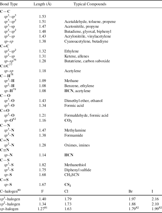
aThe values given are average lengths and do not necessarily apply exactly to the compounds mentioned.80 [Reproduced from Allen F.H.; Kennard, O.; Watson, D.G.; Brammer, L.; Orpen, A.G.; Taylor R. J. Chem. Soc. Perkin Trans. 2 1987, S1–S19 with permission from the Royal Society of Chemistry.]
A theoretical study has been reported, using computer simulation to apply encapsulation, strapping back, and stiffening to “squeeze” C–C bonds, leading to shorter bonds than would be observed if hybridization and conjugative effects operated alone.74 The additional strain caused by threefold symmetric geometry constraints is believed responsible for this effect rather than changes in hybridization alone, as postulated by others.75–82
There are indications that a C–D bond is slightly shorter than a corresponding C–H bond. Thus, electron-diffraction measurements of C2H6 and C2D6 showed a C–H bond distance of 1.1122 ± 0.0012 Å and a C–D distance of 1.1071 ± 0.0012 Å.59
As seen in Table 1.5, carbon bonds are shortened by increasing s character. This is most often explained by the fact that, as the percentage of s character in a hybrid orbital increases, the orbital becomes more like an s orbital and hence is held more tightly by the nucleus than an orbital with less s character. However, other explanations have also been offered (see Sec. 2.C), and the matter is not completely settled. In general, molecules with one π bond (X=X) have shorter bond distances when compared to single bonds, X–X, and molecules with two π bonds (X X) have even shorter bond lengths. Indeed, the bond length clearly decreases in the molecules H3C–CH3, H2C=CH2, and HC
 CH: C–C bond lengths of 1.538, 1.338, and 1.203 Å.83 There is work that suggests the absence of σ bonds may play a role in producing short bond distances in molecules that contain only π bonds.84 This suggests that σ bonds prevent π bonds from adopting their optimal shorter distances. Such bonds occur in some organometallic compounds.
1.K. Bond Angles
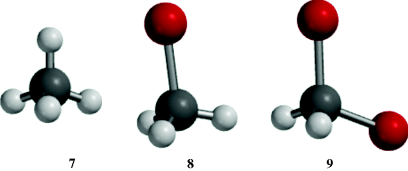
The bond angles of sp3 carbon should be the tetrahedral angle 109°28′ when the four atoms or groups are relatively small and identical, as in methane, neopentane, or carbon tetrachloride. As atoms or groups become larger, bond angles are distorted to accommodate the larger size of the attached units. In most cases, the angles deviate a little from the pure tetrahedral value unless two or more units are very large. Molecular models 7–9 illustrate this phenomenon. The H–C–H bond angles in methane (7) are calculated for the model to be 109°47′, whereas the Br–C–H bond angle in 8 is calculated to be 108.08° and the Br–C–Br bond angle in 9 is calculated to be 113.38°. Note that the C–Br bond length is longer than the C–H bond lengths. As the bond angles expand to accommodate the larger atoms, the H–C–H bond angles in 8 and 9 must compress to a smaller angle. In 2-bromopropane, the bromine atom also has a methyl group (compare with bromomethane 8 where Br competes with H) and, the C–C–Br angle in 2-bromopropane is 114.2°.85
Variations are generally found from the ideal values of 120° and 180° for sp2 and sp carbon, respectively. These deviations occur because of slightly different hybridizations; that is, a carbon bonded to four other atoms hybridizes one s and three p orbitals, but the four hybrid orbitals thus formed are generally not exactly equivalent, nor does each contain exactly 25% s and 75% p character. Because the four atoms have (in the most general case) different electronegativities, each makes its own demand for electrons from the carbon atom.86 The carbon atom supplies more p character when it is bonded to more electronegative atoms, so that in chloromethane, for example, the bond to chlorine has somewhat > 75% p character, which of course requires that the other three bonds have somewhat less, since there are only three p orbitals (and one s) to be divided among the four hybrid orbitals.87 Of course, in strained molecules (e.g., 3–6), the bond angles may be greatly distorted from the ideal values (also see Sec. 4.Q).
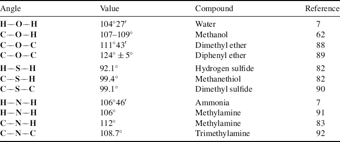
For molecules that contain oxygen and nitrogen, angles of 90° are predicted from p2 bonding. However, as seen in Section 1.B, the angles of water and ammonia are much larger than this, as are the angles of other organic molecules that contain oxygen and nitrogen (Table 1.6).88–92 In fact, they are much closer to the tetrahedral angle of 109°28′ than to 90°. These facts have led to the suggestion that in these compounds oxygen and nitrogen use sp3 bonding. Using the hybridization model, these atoms are said to form bonds by the overlap of two (or three) p orbitals with 1s orbitals of the hydrogen atoms, which means that they hybridize their 2s and 2p orbitals to form four sp3 orbitals and then use only two (or three) of these for bonding with hydrogen, the others remaining occupied by unshared pairs (also called lone pairs). If this description is valid, and it is generally accepted by most chemists today,93 it becomes necessary to explain why the angles of these two compounds are in fact not 109°28′ but a few degrees smaller. One explanation that has been offered is that the unshared electron pair actually has a greater steric requirement (see Sec. 4.Q) than the electrons in a bond, since there is no second nucleus to draw away some of the electron density and the bonds are thus crowded together. However, most evidence is that unshared pairs have smaller steric requirements than bonds94 and the explanation most commonly accepted is that the hybridization is not pure sp3. As seen above, an atom supplies more p character when it is bonded to more electronegative atoms. An unshared pair may be considered to be an “atom” of the lowest possible electronegativity, since there is no attracting power at all. Consequently, the unshared pairs have more s and the bonds more p character than pure sp3 orbitals, making the bonds somewhat more like p2 bonds and reducing the angle. However, these arguments ignore the steric effect of the atoms or groups attached to oxygen or nitrogen. As seen in Table 1.6, oxygen, nitrogen, and sulfur angles generally increase with decreasing electronegativity of the substituents. Note that the explanation given above cannot explain why some of these angles are greater than the tetrahedral angle.
Table 1.6 Oxygen, Sulfur, and Nitrogen Bond Angles in Some Compounds.
1.L Bond Energies95
There are two kinds of bond energy. The energy necessary to cleave a bond to give the constituent radicals is called the dissociation energy (D). For example, D for H2O → HO + H is 118 kcal mol−1 (494 kJ mol−1). However, this is not taken as the energy of the O–H bond in water, since D for H–O → H + O is 100 kcal mol−1 (418 kJ mol−1). The average of these two values, 109 kcal mol−1 (456 kJ mol−1), is taken as the bond energy (E). In diatomic molecules, of course, D = E.
The D values may be easy or difficult to measure. They can be estimated by various techniques.96 When properly applied, “Pauling's original electronegativity equation accurately describes homolytic bond dissociation enthalpies of common covalent bonds, including highly polar ones, with an average deviation of (1.5 kcal mol−1 (~6.3 kJ mol−1) from literature values)”.97 Whether measured or calculated, there is no question as to what D values mean. With E values the matter is not so simple. For methane, the total energy of conversion from CH4 to C + 4H (at 0 K) is 393 kcal mol−1 (1644 kJ mol−1).98 Consequently, E for the C–H bond in methane is 98 kcal mol−1 (411 kJ mol−1) at 0 K. The more usual practice is not to measure the heat of atomization (i.e., the energy necessary to convert a compound to its atoms) directly, but to calculate it from the heat of combustion. Such a calculation is shown in Fig. 1.12.
Fig. 1.12 Calculation of the heat of atomization of ethane at 25 °C.

Heats of combustion are very accurately known for hydrocarbons.99 For methane, the value at 25 °C is 212.8 kcal mol−1 (890.4 kJ mol−1), which leads to a heat of atomization of 398.0 kcal mol−1 (1665 kJ mol−1) or a value of E for the C–H bond at 25 °C of 99.5 kcal mol−1 (416 kJ mol−1). This method is fine for molecules like methane in which all the bonds are equivalent, but for more complicated molecules, assumptions must be made. Thus for ethane, the heat of atomization at 25 °C is 676.1 kcal mol−1 or 2829 kJ mol−1 (Fig. 1.12), and it must be decided how much of this energy is due to the C–C bond and how much to the six C–H bonds. Any assumption must be artificial, since there is no way of actually obtaining this information, and indeed the question has no real meaning. If the assumption is made that E for each of the C–H bonds is the same as E for the C–H bond in methane (99.5 kcal mol−1 or 416 kJ mol−1), then 6 × 99.5 (or 416) = 597.0 (or 2498), leaving 79.1 kcal mol−1 (331 kJ mol−1) for the C–C bond. However, a similar calculation for propane gives a value of 80.3 (or 336) for the C–C bond, and for isobutane, the value is 81.6 (or 341). A consideration of heats of atomization of isomers also illustrates the difficulty. The E values for the C–C bonds in pentane, isopentane, and neopentane, similarly calculated from heats of atomization, are (at 25 °C) 81.1, 81.8, and 82.4 kcal mol−1 (339, 342, 345 kJ mol−1), respectively, even though all of them have twelve C–H bonds and four C–C bonds.
These differences have been attributed to various factors caused by the introduction of new structural features. Thus isopentane has a tertiary carbon whose C–H bond does not have exactly the same amount of s character as the C–H bond in pentane, which for that matter contains secondary carbons not possessed by methane. It is known that D values, which can be measured, are not the same for primary, secondary, and tertiary C–H bonds (see Table 5.2). There is also the steric factor (see Sec. 4.Q). Hence it is certainly incorrect to use the value of 99.5 kcal mol−1 (416 kJ mol−1) from methane as the E value for all C–H bonds. Several empirical equations have been devised that account for these factors; the total energy can be computed100 if the proper set of parameters (one for each structural feature) is inserted. Of course, these parameters are originally calculated from the known total energies of some molecules that contain the structural feature.
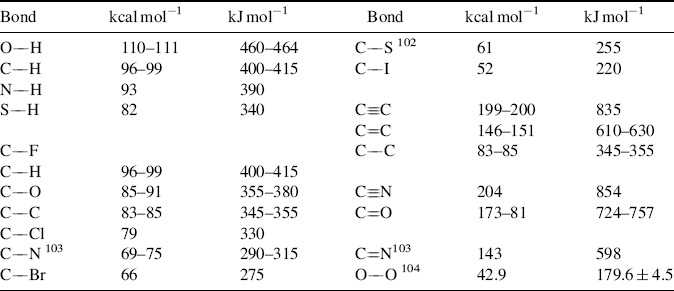
Table 1.7 gives E values for various bonds.101–104 The values given are averaged over a large series of compounds. The literature contains charts that take hybridization into account (thus an sp3 C–H bond does not have the same energy as an sp2 C–H bond).105 Bond dissociation energies, both calculated and experientially determined, are constantly being refined. Improved values are available for the O–O bond of peroxides,106 the C–H bond in alkyl amines,107 the N–H bond in aniline derivatives,108 the N–H bond in protonated amines,109 the O–H bond in phenols,110 the C–H bond in alkenes,111 amides and ketones,112 and in CH2X2 and CH3X derivatives (X = COOR, C=O, SR, NO2, etc.),113 the O–H and S–H bonds of alcohols and thiols,114 and the C–Si bond of aromatic silanes.115 Solvent plays a role in the E values. When phenols bearing electron-releasing groups are in aqueous media, calculations show that the bond dissociation energies decrease due to hydrogen-bonding interactions with water molecules, while electron-withdrawing substituents on the phenol increase the bond dissociation energies.116
Table 1.7 Bond Energy (E) Values at 25 °C for Some Important Bond Typesa,b
aThe E values are arranged within each group in order of decreasing strength. The values are averaged over a large series of compounds.
bSee Ref. 101.
[Reprinted with permission from Lovering E.G.; Laidler, K.J. Can. J. Chem. 1960, 38, 2259. Copyright © 1960 with permission from Canadian Science Publishing or its Licensors.]
Certain generalizations can be derived from the data in Table 1.7.
Calculations suggest that covalent bond strength and also equilibrium bond length are not determined by maximum overlap of the σ valence orbitals, as described in previous sections.120 Rather, orbital interactions, Pauli repulsion, and quasiclassical electrostatic attraction determine both.
Solvents are thought to play a role in bond dissociation energy of molecules, as noted for phenol above, and also for intermediates (see Chap 5). It has been assumed that the solvation enthalpies were small and they have been largely ignored in calculations involving various reactions. Solvent effects on the bond dissociation energy of a molecule may arise from the difference in solvation enthalpies between the molecule and the key intermediate. For radical reactions that involve polar molecules, the radical–solvent interaction may be larger.121
Notes
1. See Hoffmann, R.; Schleyer, P.v.R.; Schaefer, III, H.F. Angew. Chem. Int. Ed. (Engl.) 2008, 47, 7164.
2. This treatment of orbitals is simplified by necessity. For more detailed treatments of orbital theory, as applied to organic chemistry, see Matthews, P.S.C. Quantum Chemistry of Atoms and Molecules, Cambridge University Press, Cambridge, 1986; Clark, T. A Handbook of Computational Chemistry, Wiley, NY, 1985; Albright, T.A.; Burdett, J.K.; Whangbo, M. Orbital Interactions in Chemistry, Wiley, NY, 1985; MacWeeny, R.M. Coulson's Valence, Oxford University Press, Oxford, 1980; Murrell, J.N.; Kettle, S.F.A; Tedder, J.M. The Chemical Bond, Wiley, NY, 1978; Dewar, M.J.S.; Dougherty. R.C. The PMO Theory of Organic Chemistry, Plenum, NY, 1975; Zimmerman, H.E. Quantum Mechanics for Organic Chemists, Academic Press, NY, 1975; Borden, W.T. Modern Molecular Orbital Theory for Organic Chemists, Prentice-Hall, Englewood Cliffs, NJ, 1975.
3. When wave mechanical calculations are made according to the Schrödinger equation, the probability of finding the electron in a node is zero, but this treatment ignores relativistic considerations. When such considerations are applied, Dirac has shown that nodes do have a very small electron density: Powell, R.E. J. Chem. Educ. 1968, 45, 558. See also, Ellison, F.O.; Hollingsworth, C.A. J. Chem. Educ. 1976, 53, 767; McKelvey, D.R. J. Chem. Educ. 1983, 60, 112; Nelson, P.G. J. Chem. Educ. 1990, 67, 643. For a general review of relativistic effects on chemical structures, see Pyykkö, P. Chem. Rev. 1988, 88, 563.
4. See Roothaan, C.C.J.; Weiss, A.W. Rev. Mod. Phys. 1960, 32, 194; Kolos, W.; Roothaan, C.C.J. Rev. Mod. Phys. 1960, 32, 219. For a review, see Clark, R.G.; Stewart, E.T. Q. Rev. Chem. Soc. 1970, 24, 95.
5. In this book, a pair of electrons in a bond is represented by a straight line.
6. Schwarz, W.H.E. Angew. Chem. Int. Ed. 2006, 45, 1508. For the ball-in-box model, see Pierrefixe, S.C.A.H.; Guerra, C.F.; Bickelhaupt, F.M. Chem. Eur. J. 2008, 14, 819; Pierrefixe, S.C.A.H.; Bickelhaupt, F.M. J. Phys. Chem. A. 2008, 112, 12816.
7. Bent, H.A. Chem. Rev. 1961, 61, 275, 277.
8. For an alternative representation, see Pauling, L. Theoretical Organic Chemistry, The Kekulé Symposium, Butterworth, London, 1959, pp. 2–5; Palke, W.E. J. Am. Chem. Soc. 1986, 108, 6543.
9. See Simonetta, M.; Gavezzotti, A., in Patai, S. The Chemistry of the Carbon–Carbon Triple Bond, Wiley, NY, 1978, pp. 1–56; Dale, J., in Viehe, H.G. Acetylenes, Marcel Dekker, NY, 1969, pp. 3–96.
10. For a review of metal–metal multiple bonds, see Cotton, F.A. J. Chem. Educ. 1983, 60, 713.
11. For discussions, see Schmidt, M.W.; Truong, P.N.; Gordon, M.S. J. Am. Chem. Soc. 1987, 109, 5217; Schleyer, P. von R.; Kost, D. J. Am. Chem. Soc. 1988, 110, 2105.
12. For double bonds between carbon and elements other than C, N, S, or O, see Jutzi, P. Angew. Chem. Int. Ed. 1975, 14, 232; Raabe, G.; Michl, J. Chem. Rev. 1985, 85, 419 (Si only); Wiberg, N. J. Organomet. Chem. 1984, 273, 141 (Si only); Gordon, M.S. Mol. Struct. Energ. 1986, 1, 101. For reviews of C=P and C P bonds, see Regitz, M. Chem. Rev. 1990, 90, 191; Appel, R.; Knoll, F. Adv. Inorg. Chem. 1989, 33, 259; Markovski, L.N.; Romanenko, V.D. Tetrahedron 1989, 45, 6019.
13. For Si=C bonds, see Fink, M.J.; DeYoung, D.J.; West, R.; Michl, J. J. Am. Chem. Soc. 1983, 105, 1070; Fink, M.J.; Michalczyk, M.J.; Haller, K.J.; West, R.; Michl, J. Organometallics 1984, 3, 793; West, R. Pure Appl. Chem. 1984, 56, 163; Masamune, S.; Eriyama, Y.; Kawase, T. Angew. Chem. Int. Ed. 1987, 26, 584; Shepherd, B.D.; Campana, C.F.; West, R. Heteroat. Chem. 1990, 1, 1.
14. Michalczyk, M.J.; West, R.; Michl, J. J. Am. Chem. Soc. 1984, 106, 821, Organometallics 1985, 4, 826.
15. Miller, J.S.; Novoa, J.J. Acc. Chem. Res. 2007, 40, 189.
16. See Ballard, R.E. Photoelectron Spectroscopy and Molecular Orbital Theory, Wiley, NY, 1978; Rabalais, J.W. Principles of Ultraviolet Photoelectron Spectroscopy, Wiley, NY, 1977; Baker, A.D.; Betteridge, D. Photoelectron Spectroscopy, Pergamon, Elmsford, NY, 1972; Turner, D.W.; Baker, A.D.; Baker, C.; Brundle, C.R. High Resolution Molecular Photoelectron Spectroscopy, Wiley, NY, 1970. For reviews, see Westwood, N.P.C. Chem. Soc. Rev. 1989, 18, 317; Baker, C.; Brundle, C.R.; Thompson, M. Chem. Soc. Rev. 1972, 1, 355; Bock, H.; Ramsey, B.G. Angew. Chem. Int. Ed. 1973, 12, 734; Turner, D.W. Adv. Phys. Org. Chem. 1966, 4, 31. For the IUPAC descriptive classification of various electron spectroscopy techniques, see Porter, H.Q.; Turner, D.W. Pure Appl. Chem. 1987, 59, 1343.
17. The correlation is not perfect, but the limitations do not seriously detract from the usefulness of the method. The technique is not limited to vacuum UV radiation. Higher energy radiation can also be used.
18. From Brundle, C.R.; Robin, M.B., in Nachod, F.C.; Zuckerman, J.J. Determination of Organic Structures by Physical Methods, Vol. 3, Academic Press, NY, 1971, p. 18.
19. Brundle, C.R.; Robin, M.B.; Basch, H. J. Chem. Phys. 1970, 53, 2196; Baker, A.D.; Betteridge, D.; Kemp, N.R.; Kirby, R.E. J. Mol. Struct. 1971, 8, 75; Potts, A.W.; Price, W.C. Proc. R. Soc. London, Ser, A 1972, 326, 165.
20. A third band, at 290 eV, caused by the 1s electrons of carbon, can also be found if radiation of sufficiently high energy is used.
21. See Robinson, J.W., Practical Handbook of Spectroscopy, CRC Press, Boca Raton, FL, 1991, p. 178.
22. Novak, I.; Potts, A.W. Tetrahedron 1997, 53, 14713.
23. It has been argued that although the Lewis picture of two electrons making up a covalent bond may work well for organic compounds, it cannot be successfully applied to the majority of inorganic compounds: J rgensen, C.K. Top. Curr. Chem. 1984, 124, 1.
24. For a review concerning sulfur compounds with a valence shell larger than eight, see Salmond, W.G. Q. Rev. Chem. Soc. 1968, 22, 235.
25. For a collection of articles on this topic, see Sen, K.D.; J rgensen, C.K. Electronegativity (Vol. 6 of Structure and Bonding), Springer, NY, 1987. For a review, see Batsanov, S.S. Russ. Chem. Rev. 1968, 37, 332.
26. Taken from Pauling, L. The Nature of the Chemical Bond, 3rd ed., Cornell University Press, Ithaca, NY, 1960, p. 93, except for the value for Na, which is from Sanderson, R.T. J. Am. Chem. Soc. 1983, 105, 2259; J. Chem. Educ. 1988, 65, 112, 223.
27. See Sanderson, R.T. J. Am. Chem. Soc. 1983, 105, 2259; J. Chem. Educ. 1988, 65, 112, 223.
28. See Huheey, J.E. Inorganic Chemistry, 3rd ed., Harper and Row, NY, 1983, pp. 146–148; Mullay, J., in Sen, K.D.; J rgensen, C.K. Electronegativity (Vol. 6 of Structure and Bonding), Springer, NY, 1987, p. 9.
29. Hinze, J.; Jaffé, H.H. J. Am. Chem. Soc. 1962, 84, 540; Rienstra-Kiracofe, J.C.; Tschumper, G.S.; Schaefer, III, H.F.; Nandi, S.; Ellison, G.B. Chem. Rev. 2002, 102, 231.
30. Allen, L.C. J. Am. Chem. Soc. 1989, 111, 9003.
31. Walsh, A.D. Discuss. Faraday Soc. 1947, 2, 18; Bergmann, D.; Hinze, J., in Sen, K.D.; J rgensen, C.K. Electronegativity (Vol. 6 of Structure and Bonding), Springer, NY, 1987, pp. 146–190.
32. Inamoto, N.; Masuda, S. Chem. Lett. 1982, 1003. See also, Bratsch, S.G. J. Chem. Educ. 1988, 65, 223; Mullay, J. J. Am. Chem. Soc. 1985, 107, 7271; Zefirov, N.S.; Kirpichenok, M.A.; Izmailov, F.F.; Trofimov, M.I. Dokl. Chem. 1987, 296, 440; Boyd, R.J.; Edgecombe, K.E. J. Am. Chem. Soc. 1988, 110, 4182.
33. A magnetically anisotropic group is one that is not equally magnetized along all three axes. The most common such groups are benzene rings (see Sec. 2.I) and triple bonds.
34. This order is opposite to that expected from the field effect (Sec. 1.I). It is an example of the Baker–Nathan order (Sec. 2.M).
35. Moodie, R.B.; Connor, T.M.; Stewart, R. Can. J. Chem. 1960, 38, 626.
36. Williamson, K.L. J. Am. Chem. Soc. 1963, 85, 516; Laszlo, P.; Schleyer, P.v.R. J. Am. Chem. Soc. 1963, 85, 2709; Niwa, J. Bull. Chem. Soc. Jpn. 1967, 40, 2192.
37. See Exner, O. Dipole Moments in Organic Chemistry, Georg Thieme Publishers, Stuttgart, 1975; McClellan, A.L. Tables of Experimental Dipole Moments, Vol. 1, W.H. Freeman, San Francisco, 1963; Vol. 2, Rahara Enterprises, El Cerrito, CA, 1974.
38. For example, see Koudelka, J.; Exner, O. Collect. Czech. Chem. Commun. 1985, 50, 188, 200.
39. The values for toluene, nitrobenzene, and p-nitrotoluene are from MacClellan, A.L., Tables of Experimental Dipole Moments, Vol. 1, W.H. Freeman: San Francisco, 1963; Vol. 2, Rahara Enterprises, El Cerrito, CA, 1974. The values for phenol and p-cresol were determined by Goode, E.V.; Ibbitson, D.A. J. Chem. Soc. 1960, 4265.
40. Lide Jr., D.R.; Mann, D.E. J. Chem. Phys. 1958, 29, 914.
41. Muenter, J.S.; Laurie, V.W. J. Chem. Phys. 1966, 45, 855.
42. Actually, symmetrical tetrahedral molecules like methane do have extremely small dipole moments, caused by centrifugal distortion effects; these moments are so small that they can be ignored for all practical purposes. For CH4, μ is ~ 5.4 × 10⁻⁶D: Ozier, I. Phys. Rev. Lett. 1971, 27, 1329; Rosenberg, A.; Ozier, I.; Kudian, A.K. J. Chem. Phys. 1972, 57, 568.
43. Roberts, J.D.; Moreland, Jr., W.T. J. Am. Chem. Soc. 1953, 75, 2167.
44. This example is from Grubbs, E.J.; Fitzgerald, R.; Phillips, R.E.; Petty, R. Tetrahedron 1971, 27, 935.
45. See Schneider, H.; Becker, N. J. Phys. Org. Chem. 1989, 2, 214; Bowden, K.; Ghadir, K.D.F. J. Chem. Soc. Perkin Trans. 2 1990, 1333. Also see Exner, O.; Fiedler, P. Collect. Czech. Chem. Commun. 1980, 45, 1251; Li, Y.; Schuster, G.B. J. Org. Chem. 1987, 52, 3975.
46. There has been some question as to whether it is even meaningful to maintain the distinction between the two types of effect: see Grob, C.A. Helv. Chim. Acta 1985, 68, 882; Lenoir, D.; Frank, R.M. Chem. Ber. 1985, 118, 753; Sacher, E. Tetrahedron Lett. 1986, 27, 4683.
47. See also, Ceppi, E.; Eckhardt, W.; Grob, C.A. Tetrahedron Lett. 1973, 3627.
48. For a review of field and other effects of silicon-containing groups, see Bassindale, A.R.; Taylor. P.G., in Patai, S.; Rappoport, Z. The Chemistry of Organic Silicon Compounds, pt. 2, Wiley, NY, 1989, pp. 893–963.
49. See Levitt, L.S.; Widing, H.F. Prog. Phys. Org. Chem. 1976, 12, 119.
50. See Sebastian, J.F. J. Chem. Educ. 1971, 48, 97.
51. See Wahl, Jr., G.H.; Peterson, Jr., M.R. J. Am. Chem. Soc. 1970, 92, 7238; Minot, C.; Eisenstein, O.; Hiberty, P.C.; Anh, N.T. Bull. Soc. Chim. Fr. 1980, II-119.
52. Streitwieser, Jr., A.; Klein, H.S. J. Am. Chem. Soc. 1963, 85, 2759.
53. Bent, H.A. Chem. Rev. 1961, 61, 275, p. 281.
54. See Laurence, C.; Berthelot, M.; Lucon, M.; Helbert, M.; Morris, D.G.; Gal, J. J. Chem. Soc. Perkin Trans. 2 1984, 705.
55. For tables of bond distances and angles, see Allen, F.H.; Kennard, O.; Watson, D.G.; Brammer, L.; Orpen, A.G.; Taylor, R. J. Chem. Soc. Perkin Trans. 2 1987, S1–S19 (follows p. 1914); Tables of Interatomic Distances and Configurations in Molecules and Ions Chem. Soc. Spec. Publ. No. 11, 1958; Interatomic Distances Supplement Chem. Soc. Spec. Publ. No. 18, 1965; Harmony, M.D.; Laurie, V.W.; Kuczkowski, R.L.; Schwendeman, R.H.; Ramsay, D.A.; Lovas, F.J.; Lafferty, W.J.; Maki, A.G. J. Phys. Chem. Ref. Data 1979, 8, 619–721. See Lathan, W.A.; Curtiss, L.A.; Hehre, W.J.; Lisle, J.B.; Pople, J.A. Prog. Phys. Org. Chem. 1974, 11, 175; Topsom, R.D. Prog. Phys. Org. Chem. 1987, 16, 85.
56. Burkert, U.; Allinger, N.L. Molecular Mechanics, ACS Monograph 177, American Chemical Society, Washington, 1982, pp. 6–9; Whiffen, D.H. Chem. Ber. 1971, 7, 57–61; Stals, J. Rev. Pure Appl. Chem. 1970, 20, 1, pp. 2–5.
57. Schleyer, P.v.R.; Bremer, M. Angew. Chem. Int. Ed. 1989, 28, 1226.
58. Lonsdale, K. Philos. Trans. R. Soc. London 1947, A240, 219.
59. Bartell, L.S.; Higginbotham, H.K. J. Chem. Phys. 1965, 42, 851.
60. Wagner, R.S.; Dailey, B.P. J. Chem. Phys. 1957, 26, 1588.
61. Iijima, T. Bull. Chem. Soc. Jpn. 1972, 45, 1291.
62. Tables of Interatomic Distances, Ref. 55.
63. Momany, F.A.; Bonham, R.A.; Druelinger, M.L. J. Am. Chem. Soc. 1963, 85, 3075. Also see, Lide, Jr., D.R.; Jen, M. J. Chem. Phys. 1963, 38, 1504.
64. Bonham, R.A.; Bartell, L.S.; Kohl, D.A. J. Am. Chem. Soc. 1959, 81, 4765.
65. Hilderbrandt, R.L.; Wieser, J.D. J. Mol. Struct. 1973, 15, 27.
66. Allen, F.H.; Kirby, A.J. J. Am. Chem. Soc. 1984, 106, 6197; Jones, P.G.; Kirby, A.J. J. Am. Chem. Soc. 1984, 106, 6207.
67. White, J.M.; Robertson, G.B. J. Org. Chem. 1992, 57, 4638.
68. Except where noted, values are from Allen, F.H.; Kennard, O.; Watson, D.G.; Brammer, L.; Orpen, A.G.; Taylor, R. J. Chem. Soc. Perkin Trans. 2 1987, S1–S19 (follows p. 1914). In this source, values are given to three significant figures.
69. Kaupp, G.; Boy, J Angew. Chem. Int. Ed. 1997, 36, 48.
70. Ehrenberg, M. Acta Crystallogr. 1966, 20, 182.
71. Toda, F.; Tanaka, K.; Stein, Z.; Goldberg, I. Acta Crystallogr., Sect. C 1996, 52, 177.
72. Toda, F.; Tanaka, K.; Watanabe, M.; Taura, K.; Miyahara, I.; Nakai, T.; Hirotsu, K. J. Org. Chem. 1999, 64, 3102.
73. Tanaka, K.; Takamoto, N.; Tezuka, Y.; Kato, M.; Toda, F. Tetrahedron 2001, 57, 3761.
76. Costain, C.C.; Stoicheff, B.P. J. Chem. Phys. 1959, 30, 777.
77. For a full discussion of alkyne bond distances, see Simonetta, M.; Gavezzotti, A. in Patai, S. The Chemistry of the Carbon–Carbon Triple Bond, Wiley, NY, 1978.
78. See Henry, B.R. Acc. Chem. Res. 1987, 20, 429.
79. Bartell, L.S.; Roth, E.A.; Hollowell, C.D.; Kuchitsu, K.; Young, Jr., J.E. J. Chem. Phys. 1965, 42, 2683.
80. For reviews of carbon–halogen bonds, see Trotter, J. in Patai, S. The Chemistry of the Carbon–Halogen Bond, pt. 1; Wiley, NY, 1973, pp. 49–62; Mikhailov, B.M. Russ. Chem. Rev. 1971, 40, 983.
81. Lide, Jr., D.R. Tetrahedron 1962, 17, 125.
82. Rajput, A.S.; Chandra, S. Bull. Chem. Soc. Jpn. 1966, 39, 1854.
74. Huntley, D.R.; Markopoulos, G.; Donovan, P.M.; Scott, L.T.; Hoffmann, R. Angew. Chem. Int. Ed. 2005, 44, 7549.
75. See Tanaka, M; Sekiguchi, A. Angew. Chem. Int. Ed. 2005, 44, 5821–5823.
83. Vannes, G.J.H.; Vos, A. Acta Crystallogr. Sect. B 1978, B34, 1947; Vannes, G.J.H.; Vos, A. Acta Crystallogr. Sect. B, 1979, B35, 2593; Mcmullan, R.K.; Kvick, A. Acta Crystallogr. Sect. B, 1992, B48, 726.
84. Jemmis, E.D.; Pathak, B.; King, R.B.; Schaefer, III, H.F. Chem. Commun. 2006, 2164.
85. Schwendeman, R.H.; Tobiason, F.L. J. Chem. Phys. 1965, 43, 201.
86. For a review of this concept, see Bingel, W.A.; Lüttke, W. Angew. Chem. Int. Ed. 1981, 20, 899.
87. This assumption has been challenged: see Pomerantz, M.; Liebman, J.F. Tetrahedron Lett. 1975, 2385.
88. Blukis, V.; Kasai, P.H.; Myers, R.J. J. Chem. Phys. 1963, 38, 2753.
89. Abrahams, S.C. Q. Rev. Chem. Soc. 1956, 10, 407.
90. Iijima, T.; Tsuchiya, S.; Kimura, M. Bull. Chem. Soc. Jpn. 1977, 50, 2564.
91. Lide, Jr., D.R. J. Chem. Phys. 1957, 27, 343.
92. Lide, Jr., D.R.; Mann, D.E. J. Chem. Phys. 1958, 28, 572.
93. An older theory holds that the bonding is indeed p2, and that the increased angles come from repulsion of the hydrogen or carbon atoms. See Laing, M., J. Chem. Educ. 1987, 64, 124.
94. See Blackburne, I.D.; Katritzky, A.R.; Takeuchi, Y. Acc. Chem. Res. 1975, 8, 300; Aaron, H.S.; Ferguson, C.P. J. Am. Chem. Soc. 1976, 98, 7013; Anet, F.A.L.; Yavari, I. J. Am. Chem. Soc. 1977, 99, 2794; Vierhapper, F.W.; Eliel, E.L. J. Org. Chem. 1979, 44, 1081; Gust, D.; Fagan, M.W. J. Org. Chem. 1980, 45, 2511. For other views, see Lambert, J.B.; Featherman, S.I. Chem. Rev. 1975, 75, 611; Breuker, K.; Kos, N.J.; van der Plas, H.C.; van Veldhuizen, B. J. Org. Chem. 1982, 47, 963.
95. Blanksby, S.J.; Ellison, G.B. Acc. Chem. Res. 2003, 36, 255. For reviews including methods of determination, see Wayner, D.D.M.; Griller, D. Adv. Free Radical Chem. (Greenwich, Conn.) 1990, 1, 159; Kerr, J.A. Chem. Rev. 1966, 66, 465; Wiberg, K.B., in Nachod, F.C.; Zuckerman, J.J. Determination of Organic Structures by Physical Methods, Vol. 3, Academic Press, NY, 1971, pp. 207–245.
96. Cohen, N.; Benson, S.W. Chem. Rev. 1993, 93, 2419; Korth, H.-G.; Sicking, W. J. Chem. Soc. Perkin Trans. 2 1997, 715.
97. Matsunaga, N.; Rogers, D.W.; Zavitsas, A.A. J. Org. Chem, 2003, 68, 3158.
98. For the four steps, D values are 101–102, 88, 124, and 80 kcal mol−1 (423–427, 368, 519, and 335 kJ mol−1), respectively, though the middle values are much less reliable than the other two: Knox, B.E.; Palmer, H.B. Chem. Rev. 1961, 61, 247; Brewer, R.G.; Kester, F.L. J. Chem. Phys. 1964, 40, 812; Linevsky, M.J. J. Chem. Phys. 1967, 47, 3485.
99. See Cox, J.D.; Pilcher, G., Thermochemistry of Organic and Organometallic Compounds, Academic Press, NY, 1970; Domalski, E.S. J. Phys. Chem. Ref. Data 1972, 1, 221–277; Stull, D.R.; Westrum Jr., E.F.; Sinke, G.C. The Chemical Thermodynamics of Organic Compounds, Wiley, NY, 1969.
100. For a review, see Cox, J.D.; Pilcher, G. Thermochemistry of Organic and Organometallic Compounds, Academic Press, NY, 1970, pp. 531–597. See also, Gasteiger, J.; Jacob, P.; Strauss, U. Tetrahedron 1979, 35, 139.
101. These values, except where noted, are from Lovering, E.G.; Laidler, K.J. Can. J. Chem. 1960, 38, 2367; Levi, G.I.; Balandin, A.A. Bull. Acad. Sci. USSR, Div. Chem. Sci. 1960, 149.
102. Grelbig, T.; Pötter, B.; Seppelt, K. Chem. Ber. 1987, 120, 815.
103. Bedford, A.F.; Edmondson, P.B.; Mortimer, C.T. J. Chem. Soc. 1962, 2927.
104. The average of the values obtained was DHo(O–O). dos Santos, R.M.B.; Muralha, V.S.F.; Correia, C.F.; Simões, J.A.M. J. Am. Chem. Soc. 2001, 123, 12670.
105. Cox, J.D.; Pilcher, G. Thermochemistry of Organic and Organometallic Compounds, Academic Press, NY, 1970, pp. 531–597; Cox, J.D. Tetrahedron 1962, 18, 1337.
106. Bach, R.D.; Ayala, P.Y.; Schlegel, H.B. J. Am. Chem. Soc. 1996, 118, 12758.
107. Wayner, D.D.M.; Clark, K.B.; Rauk, A.; Yu, D.; Armstrong, D.A. J. Am. Chem. Soc. 1997, 119, 8925. For the α C–H bond of tertiary amines, see Dombrowski, G.W.; Dinnocenzo, J.P.; Farid, S.; Goodman, J.L. Gould, I.R. J. Org. Chem. 1999, 64, 427.
108. Bordwell, F.G.; Zhang, X.-M.; Cheng, J.-P. J. Org. Chem. 1993, 58, 6410. See also, Li, Z.; Cheng, J.-P. J. Org. Chem. 2003, 68, 7350.
109. Liu, W.-Z.; Bordwell, F.G. J. Org. Chem. 1996, 61, 4778.
110. Lucarini, M.; Pedrielli, P.; Pedulli, G.F.; Cabiddu, S.; Fattuoni, C. J. Org. Chem. 1996, 61, 9259. For the O–H, E of polymethylphenols, see de Heer, M.I.; Korth, H.-G.; Mulder, P. J. Org. Chem. 1999, 64, 6969.
111. Zhang, X.-M. J. Org. Chem. 1998, 63, 1872.
112. Bordwell, F.G.; Zhang, X.-M.; Filler, R. J. Org. Chem. 1993, 58, 6067.
113. Brocks, J.J.; Beckhaus, H.-D.; Beckwith, A.L.J.; Rüchardt, C. J. Org. Chem. 1998, 63, 1935.
114. Hadad, C.M.; Rablen, P.R.; Wiberg, K.B. J. Org. Chem. 1998, 63, 8668.
115. Cheng, Y.-H.; Zhao, X.; Song, K.-S.; Liu, L.; Guo, Q.-X. J. Org. Chem. 2002, 67, 6638.
116. Guerra, M.; Amorati, R.; Pedulli, G.F. J. Org. Chem. 2004, 69, 5460.
117. Feng, Y.; Liu, L.; Wang, J.-T.; Zhao, S.-W.; Guo, Q.X. J. Org. Chem. 2004, 69, 3129; Song, K.-S.; Liu, L.; Guo, Q.X. Tetrahedron 2004, 60, 9909.
118. Coote, M.L.; Pross, A.; Radom, L. Org. Lett. 2003, 5, 4689.
119. See Miller, S.I. J. Chem. Educ. 1978, 55, 778.
120. Krapp, A.; Bickelhaupt, F.M.; Frenking, G. Chem.: Eur. J. 2006, 12, 9196.
121. Borges dos Santos, R.M.; Costa Cabral, B.J.; Martinho Simões, J.A. Pure Appl. Chem. 2007, 79, 1369.

