Patterns of Water and Sediment Flow with Their Potential Water-Harvesting Response
A thing is right when it tends to preserve the integrity, stability, and beauty of the biotic community. It is wrong when it tends otherwise.
—Aldo Leopold, from “The Land Ethic” in A Sand County Almanac
PATTERNS OR TRACKS
The patterns or “tracks” left by the flow of water and sediment are excellent guides to direct you in selecting and placing appropriate water-harvesting strategies. Both erosion and deposition are natural occurrences that create characteristic patterns. Erosion creates concave landforms when sediment is carried away by runoff water, leaving depressions such as rills and gullies behind. When sediment-laden runoff water is slowed or spread out, it loses the energy (some may think “force”) needed to carry sediment. The largest sediment drops out of slowing water first. If the water continues to slow, smaller sediment is deposited. Thus, in places where water flow has slowed, deposited sediment creates convex landforms such as alluvial fans and depositional bars.
Erosion and deposition are naturally kept in balance in healthy watersheds by the presence of vegetation, porous living soils, and the slowly occurring erosion that is a normal part of a dynamic equilibrium, and which gradually moves sediment downslope. As the components of sediment—organic matter, soil, and inorganic material—migrate and deposit downslope, they are replaced upslope by onsite leaf drop from vegetation; and leaf drop, soil, and inorganic material migrating downwards from higher upslope. At the same time material “migrates upslope” in the form of animal droppings containing organic material and seeds that build soil and grow vegetation.
In unhealthy watersheds, erosion far surpasses deposition and can carve deep cuts in the land, leading to a rapid loss of water, organic matter, soil, and inorganic material. A deep erosion cut is a sign of an unstable landscape that is losing valuable organic and inorganic resources. Learning to recognize erosion patterns, and understand their causes, is essential in planning effective water-harvesting strategies that break the erosion triangle shown in figure A1.1.
Fig. A1.1. Erosion triangle
SPEED, DEPTH, and VOLUME refer to three characteristics of water flowing on the broad surface of the land and within channels. Reduce any of the three by SLOWING, SPREADING, and/or SINKING the water’s flow, and you begin to break the erosion cycle. The more places you break the cycle, the more you reduce erosion. If you put a water-harvesting strategy—such as a berm ’n basin, one-rock dam, or infiltration basin—in the path of flowing water, you will reduce erosion by reducing the SPEED of water flow, while increasing the time the water has to linger, cycle, and SINK into the earth below where it becomes available to support the growth of plants. The more plant life the harvested water supports, the more roots hold the soil, the more plant canopy shelters the soil, and the more biomass catches and builds the soil. Your efforts will help generate many living “speed bumps” on the erosion highway.
The greater the DEPTH of flowing water at any given point, the greater the water’s power to erode sediment when compared to shallower water moving at the same speed. If numerous water-harvesting strategies are placed to SPREAD the water’s flow from top-to-bottom throughout a watershed, then erosion will be decreased by reducing the DEPTH of flowing water. At the same time, SPREADING the water increases the time period and spatial area of contact between water and earth, increasing the total VOLUME of water infiltrating into the subsurface. Water that SINKS into the subsurface migrates laterally and downward through the force of capillary action and gravity. This leads to longer duration water storage and higher soil-moisture availability than occurs when water flows rapidly across the land surface or within channels and quickly evaporates.
The greater the VOLUME of water flowing over land or within a channel, the more sediment it can carry. If you place a number of water-harvesting and water-infiltrating strategies starting at the top of the watershed, you will SINK a larger VOLUME of water higher in the watershed, reducing erosion by reducing the overall VOLUME of unchecked surface water flow throughout the watershed. With more contact time and contact area between water and earth, more water will be absorbed into the subsurface. This is like placing speed bumps from the top of a watershed to the bottom so the water never gets a chance to destructively speed up and accumulate in an unmanageable VOLUME.
Below are descriptions of a number of water, erosion, and deposition flow patterns, along with descriptions of how these patterns might change in response to constructing water-harvesting earthworks (see chapters 10 and 12 in Volume 2 for more). Many of the earthwork techniques are introduced and illustrated in chapter 3. These are covered in more detail in Rainwater Harvesting for Drylands and Beyond, Volume 2: Water-Harvesting Earthworks, along with the publications Let the Water Do the Work: Induced Meandering, an Evolving Method for Restoring Incised Chanels by Bill Zeedyk and Van Clothier (found at QuiviraCoalition.org and StreamDynamics.us) and Erosion Control Field Guide by Craig Sponholtz and Avery C. Anderson, (found at QuiviraCoalition.org and WatershedArtisans.com). Bill Zeedyk and Van Clothier greatly improved this appendix with their review, editing, images, and sharing of their evolving water- and sediment-harvesting strategies and insights, as did Craig Sponholtz, who also contributed much of the writing.
PATTERNS AND RESPONSE
SEDIMENT SIZE AND TRANSPORT
PATTERN: Sediment moves—or “flows”—along with water flows. Always consider both water flow and sediment flow in design. The lower the velocity or energy of the flow, the smaller the size of sediments the water can carry. Velocity is reduced when the steepness of the flow’s path becomes more gradual, the width of the flow is widened as its depth is lessened, and/or when the channel’s bed and banks come to be rougher. Steep, fast-moving rivers have enough energy to easily transport boulders. Gently sloped, slow-moving streams may only be able to transport grains of sand and smaller particles. The velocity of water flowing across the broad landscape also affects the size of sediment it can transport, but the size range of transported materials is much smaller. Stationary, ponded water has no energy to hold particles except for the finest suspended clay particles.
RESPONSE: The size of sediment that you observe has been moved by flowing water indicates the velocity of water flows that have occurred there—primarily during the last flood. Determining typical water flow velocity—along with the quantity and likely sediment sizes the flow will transport—is key to selecting, placing, and sizing appropriate water-harvesting and erosion-control structures. It is almost always better to stay out of boulder-strewn drainages, which have potentially intense flows. Instead focus water-harvesting and erosion-control efforts on more gentle slopes in the broad landscape and in the smaller drain-ages. Rock structures placed within channels should be constructed using rocks that are larger than 90% of the typical naturally deposited rock. If you are building a rock structure in a channel full of sand with no naturally deposited rock, you may want to import and use rock having a median dimension (not the shortest width nor the longest width of the rock) that measures approximately 1/8th of the total channel width (for example, in a 6-foot wide channel appropriate for hand work, 8- to 10-inch rock would be used to construct a one-rock dam across the channel width). The rocks in these structures should be tightly and carefully placed so they do not easily wash away. New rock structures are structurally weakest in the time period before sediment carried by smaller water flows has been deposited in and around the structures. To avoid impacts from large storms occurring soon after construction, spaces between the rocks, and on the upstream side of rock structures, can be pre-filled with gravel and/or smaller sediment to mimic the deposition that would occur in smaller flows.
When we harvest or manage flowing water, we are also harvesting and managing the sediment transported with that water. This is especially true in dryland watersheds where the relative sparseness of vegetation results in a sediment-rich environment. An ample supply of sediment is the unavoidable companion of any water harvested in erosive landscapes. Harvesting sediment-rich water can be a challenge but can also yield assets.
Sediment is an asset in in-channel sediment-harvesting structures such as one-rock dams when it fills in the spaces between rocks and forms a sediment-deposit on the upstream side of the structure, which readily absorbs and holds water for plants. It is an asset on alluvial fans and the broad landscape where media luna- (crescent moon-) shaped rock berms/sheet flow spreaders, or dense bands of native grass, slow water and collect sediment to provide a well-hydrated growing medium for more vegetation (see figures in the sheet flow spreader section of chapter 3). Here, the vegetation’s stabilizing roots and above-ground growth slow, spread, and harvest still more water and sediment. See Floodplains, Incised Channels, Crossover Riffles, and Alluvial Fans below for more information.
Harvesting sediment-laden water can be a challenge when water-harvesting earthworks such as basins, swales, and other earthen structures that “pond” water, fill in with sediment. This can reduce water-holding capacity, create unexpected overflow, and reduce the effective lifespan of water-harvesting earthworks, while creating the on-going job of removing the sediment. To reduce unwanted sedimentation of earthworks, revegetate the watershed above the earthworks using the sediment as a soil-building resource, especially if it is composed of fine particles, organic matter, and topsoil. Wherever possible direct the flow path of sediment-laden water across well-vegetated, gently sloping landforms before the flow enters basins and swales (see Alluvial Fans pattern section further on). This will allow fertile sediment to be deposited and utilized rather than being collected in water-pooling earthworks.
Sediment traps can be incorporated into the design of water-harvesting structures if it is not possible to intercept sediment prior to runoff water entering a basin or other earthwork. Sediment traps are basins designed to pond runoff and collect sediment, while allowing relatively clear runoff water to overflow to other water-harvesting basins. Sediment traps should be easily accessible and should be cleaned out frequently between storms. Sediment traps should not be planted. Depending on sediment sizes, the collected sediment can meet a variety of needs ranging from fine-grained material for plastering to a useful supply of gravel. Mr. Phiri similarly uses the sand collected in his reservoirs (chapter 1).
SHEET FLOW
Sheet flow is the relatively even distribution of runoff water flowing down the slope of the land rather than being focused into distinct channels. If after a large rainfall, you don’t see distinct channels in an area of sloping land, water has flowed across the landscape as sheet flow. Such flow is beneficial unless the landscape is so disturbed or degraded that sheet flow leads to sheet erosion. Microdetritus berms and pedestals are indicators of sheet flow and sheet erosion, respectively, and are described below.
Microdetritus Berms
PATTERN: Microdetritus berms are small, curved lines of leaf duff, animal scat, twigs and other organic matter that were carried by sheet flow then deposited perpendicular to the direction of flow. The outer bow of the curve usually points downslope. These are typically less than two inches (51 mm) high, and often remain only a few weeks or less after a rainfall. They may be found in the broad landscape and on gentle slopes in yards, but are not found in drainages. (See figure A1.2.)
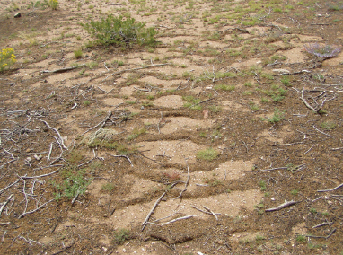
Fig. A1.2. Microdetritus berms after sheet flow has ceased. Sheet flow was from top of photo to bottom of photo. Credit: Craig Sponholtz
RESPONSE: These tiny berms of organic matter indicate recent sheet flow. Their presence typically signals there is no pressing need for erosion control. They do help indicate the direction of land slope and water flow—information which is useful when laying out contour berm ’n basins, boomerang berms, mulch berms, and sheet flow spreaders, and when planting on-contour.
Pedestals
PATTERN: As stabilizing vegetation in an area is impacted by overgrazing, changes in land use, or other destabilizing factors, once-benign sheet flow can begin to cause sheet erosion. Pedestals are isolated mounds of soil that remain after the exposed ground outside the perimeter of the pedestals is eroded away (fig. A1.3). A close look reveals that a pebble cap or plant roots and a canopy of leaves and branches have kept the earthen pedestal from washing away from the direct blow of falling raindrops and the resulting runoff.
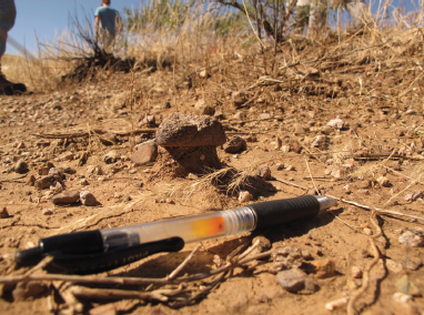
Fig. A1.3. Pedestal pattern on Empire Ranch in southeastern Arizona
RESPONSE: The presence of pedestals indicates that year-round soil-sheltering and soil-anchoring groundcover is lacking, and sheet flow has become sheet erosion. To respond, utilize strategies that re-establish dispersed—rather than concentrated— sheet flow, slow the speed and depth of runoff, increase infiltration, and support more vegetation. You can also protect the soil surface from the impact of raindrops using mulch and you can change land management practices. Grazing practices may need to be changed, access by ATVs and other off-road vehicles may need to be blocked, and even human foot traffic may need to be curtailed or redirected, if these activities are preventing re-establishment of perennial groundcover.
To stabilize eroding sheet flow areas in home landscapes and smaller landholdings, it may be appropriate to construct infiltration basins and contour or boomerang berms using earth, brush, mulch, or one-course structures of readily available rock. Imprinting and/or hydroseeding is better suited for badly disturbed broad-scale applications.
Monitor the sheet erosion by driving an array of large landscape nails into the ground up to the nails’ heads. If pedestals form below the nail heads over time then sheet erosion is still occurring. The rate of soil loss can be measured in inches or millimeters per year.
CHANNEL FLOW
Channel flow consists of water concentrated within distinct channels or drainages. The source of the water may be localized rainfall, remote rainfall, springs, shallow groundwater, snowmelt from mountains, or other sources. The water may flow all the time (perennial flow), it may cease flow periodically (intermittent flow), or it may flow only in response to storm events (ephemeral flow). When trying to find erosional and depositional patterns in channels, look at Sediment Size and Transport (above), and look for Headcuts, Rills, Gullies, Floodplains, Incised Channels, Meandering Waterways, Bank Cutting and Pools, Crossover Riffles, and other patterns discussed below.
Headcuts
PATTERN: A headcut is an erosional feature that cuts a deep gouge into the earth, which quickly drains water away from the area resulting in a drying of the landscape. Headcuts can occur in uplands and within channels. Headcuts start small, but can grow to be severe. Those found within channels cut upstream or “headward” toward the headwaters of the stream, opposite the direction of water flow. Uplands headcuts and in-channel headcuts are described below.
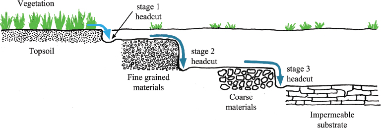
An uplands headcut is found at the point—often within a gently sloping landform—where sheet flow has concentrated into a deep, erosive concentrated flow, such as at the leading eroding edges of rills and gullies. Upland headcuts often occur in a series of stepped cuts or “waves.” They start in the topsoil, but once the cut extends down to the first layer of subsoil, another headcut frequently erodes into an even deeper layer of subsoil that is often composed of courser material than the layer above. This can lead to yet another headcut eventually digging down to a less permeable layer such as bedrock. In this way, a small headcut in the topsoil gets extended by larger headcuts in subsoil layers, and the gully gets deeper with every wave of headcuts. Uplands headcuts continue cutting upslope as long as there is soil to cut, or until they are corrected and stabilized (fig. A1.4).
Fig. A1.4. Headcut progression. Uplands headcuts tend to advance headward in series or waves of stepped cuts and propagate headward/upslope. We typically see the stage 2 headcut and miss the others. But all three must be found and mitigated. Adapted from Let the Water Do the Work by Bill Zeedyk and Van Clothier, Quivira Coalition, 2014
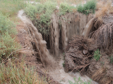
In-channel headcuts can result from disturbances that change the stability and/or elevation of part of a channel, such as road crossings that drop the bed of a drainage, loss of stabilizing vegetation due to removal or die off, or a failed dam that creates an erosive scour hole, among other causes. Once initiated, an in-channel headcut is found within an existing channel at the headcut’s pour-over lip—the location where the channel elevation changes abruptly at the point of disturbance, or even some distance downstream (possibly even out of sight) of the original disturbance. The result can be a lowering of the stream bed (see Incised Channels below) to the point where small floods no longer rise to the top of the channel’s banks and spread out on the stream’s floodplain (see Floodplains below). As the bed of the channel drops due to the initial headcut, it can spark headcuts that migrate up every tributary flowing into it. And as these tributaries drop they spark headcuts up every tributary flowing into them. During runoff events, the upland and in-channel headcuts are among the wettest parts of the landscape or channel, with water flowing over the pour-over lip or drop-off locations, scouring material away from the higher edge of the cut, while also falling as a waterfall causing turbulent scour at the base of the cut (see figure A1.5A). All of this erodes the headcut further headward. As the runoff diminishes, a headcut will continue to be one of the wettest places because this is where water will weep—gradually draining from adjacent sediments and subsoils and collecting in the low area. However, after the runoff event is over and the weeping of water has stopped, the headcut can become the driest part of the landscape because the cut opens up, or exposes, the substrata of the channel bed, and the subsoil of the uplands, to more rapid moisture loss to evaporation. As this occurs, the lip of the pour-over may further collapse due to drying and cracking as surrounding plant roots die (fig. A1.5B). These are key points to take into account of when considering response strategies.
Fig. A1.5A. Water flow pouring over a headcut. Credit: Craig Sponholtz, WatershedArtisans.com
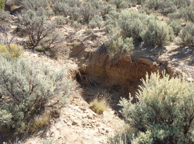
Fig. A1.5B. Dry headcut long after water flow has ceased. Credit: Craig Sponholtz, WatershedArtisans.com
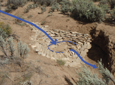
Fig. A1.5C. Rock-lined plunge pool or Zuni bowl stabilizing headcut from fig. A1.5B, just after Zuni bowl was built. During water flows, water will pool in the bowl and infiltrate between the rocks to prolong the free irrigation of vegetation that will grow through the rock and help stabilize the structure. Arrows denote water flow. Credit: Craig Sponholtz, WatershedArtisans.com
RESPONSE: Headcuts are an indicator of serious erosion problems. They need to be addressed quickly to stop channel incision. Within a gently sloping landform, one way to stop an upland headcut is to starve it of water by redirecting flow elsewhere, while taking great care not to direct the problem to a new location. Overland sheet flow should be slowed, spread out, and infiltrated into the soil to the greatest extent possible before it reaches the headcut. Water-harvesting strategies such as mulch, vegetation, infiltration basins, berm ’n basins, and sheet flow spreaders may work well in home landscapes and smaller landholdings. Imprinting, hydroseeding, and increased vegetation are better strategies for badly disturbed broad-acre areas located upslope of a headcut and outside of the channel. Perhaps the headcut is in a ditch or dirt road that has concentrated flow down a new erosive path. Look for an opportunity to redirect the water back into its more stable historic flow path.
Within the eroding channel, stabilize the headcut itself, while also spreading and infiltrating the water flow with permeable barriers appropriate to the scale of the channel. During runoff events, a rock-mulch rundown (at an uppermost uplands headcut), rock-lined plunge pool (or Zuni bowl at in-channel head-cuts), or a cross-vane prevents headward erosion by preventing the drop-off or pour-over lip from migrating. As the runoff diminishes, a rock-lined plunge pool stays full of water, supersaturating the vicinity of the headcut with water, prolonging the time soil moisture is available for plants, and maximizing stabilizing plant growth. See figures A1.5C, A1.6, and A1.7.
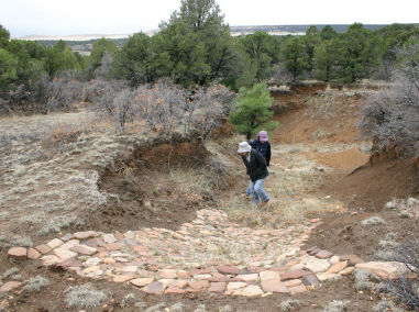
Fig. A1.6. Rock-mulch rundown stabilizing a previously erosive headcut where sheet flow transitioned to erosive channel flow at the cut. Note people are walking on a one-rock (high) dam below the rundown, and there is a second one-rock dam to the right of the lower person’s waistline. Northern New Mexico. Installation by Craig Sponholtz

Fig. A1.7. A cross-vane (keyed into bedrock on left side of photo and native boulders on the right) controlling a headcut that used to erode the edge of the road, while creating a scour pool that clears sediment and collects water for wildlife. Designed by Bill Zeedyk. Hand-built by Pima County road crew in 2007. Altar Valley, Arizona
Since headcuts often advance headward in waves of different heights, several different types of structures may be appropriate. A rock-mulch rundown is only appropriate on low-energy headcuts where sheet flow collects and first enters a channel. Zuni bowls can be used to control both upper headcuts at the point where sheet flow enters a channel and can control a headcut within a channel at the middle drop of a three-stage headcut. A one-rock dam could control a third, shallower drop at the lower end of the cutting sequence.
Rill Erosion or Runnels
PATTERN: Rills or runnels are tiny erosive drainages from which loose soil has washed away. They are the first stage of localized channel formation and are created when sheetflow collects into channelized flow due to loss of groundcover, and/or the steepness of the slope increases. They are very common on eroding slopes uphill and downhill of roadways that are cut into hillsides, or on bare dirt driveways and roads that run downslope (fig. A1.8). Rills are an early stage of the type of channel erosion that occurs upslope of small headcuts, and tend to become tributaries to gullies.
A1.8. Rill erosion. Credit: Craig Sponholtz
RESPONSE: Rills are a precursor to more erosive gullies. To prevent further degradation of the system, first spread and infiltrate sheet flow above the rill or runnel. Berm ’n basins—particularly their sheet-flow spreader variation—along with increased vegetation and the addition of mulch can all effectively break the continuity of flow from watershed to rill. Next, use brush to spread and infiltrate the flow within the rill itself. Fill the rill with brush placed lengthwise, parallel with the rill. This avoids creating the scour holes that commonly form when barriers are placed perpendicular to the flow. Place the cut base of the brush pointing upslope and branches pointing downslope so the water’s flow will help push and anchor the branches into the bed and banks of the rill. This anchoring effect can be further enhanced by pruning those branches and stems that will lay against the banks and basin of the rill to form rigid 1- to 4-inch (2.5-to 10-cm) “hooks” that anchor the brush when it is pushed into place. Avoid layering the brush too thick. You want some direct sunlight to reach the soil beneath the brush to germinate seeds and enable vegetation to grow up through the brush to trap sediment and stabilize the land.
Gullies
PATTERN: Gullies are formed as a result of channelized, concentrated, and accelerated water flow. Gullies are large eroded drainages that result from extensive head-cutting (fig. A1.9). A gully is actively eroding if it is downcutting and getting deeper (fig. A1.10). A gully is likely stabilizing if it is getting wider rather than deeper, flow is slowing and becoming shallower, and vegetation is growing within the channel and on its banks (fig. A1.10). This is how nature heals a gully and our response should mimic nature’s.
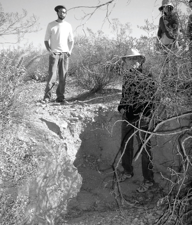
Fig. A1.9. A deepening gully just below a headcut. Avra Valley, Arizona
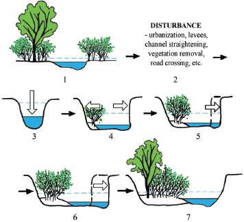
Fig. A1.10. Stable conditions deteriorate to unstable conditions, then evolve to stable conditions again.
An erosive down-cutting gully with no access to floodplain (3) evolves into a calmer, widening water channel that creates a new accessible, vegetated, sediment-trapping floodplain by beneficially eroding its own banks as it establishes a more meandering path (7).The blue area represents bankfull or normal full-channel flows just before they would begin to spill over the channel’s banks onto the floodplain, while the dotted horizontal line represents the depth of typical flood flows. Adapted from
Let the Water Do the Work
RESPONSE: Gullies are often precursors to even more severe, deeply eroded ravines. The overland flow draining toward the channel should be slowed, spread, and infiltrated into the soil as much as possible before reaching the channel. Where flow paths have been diverted by steeper ditches, trails, or roads, look for opportunities to redirect the flow back to the more gradual, historic flow path. Changing land management and installing sheet flow spreaders, imprinting, vegetation, mulch, and infiltration basins may all be appropriate above the gully.
Monitor the gully to see whether it is cutting deeper or is widening and stabilizing. If it is cutting deeper, carefully place a series of one-rock dams constructed perpendicular to the flow at crossover riffle locations to help stabilize the drainage. At the same time, repair the broader landscape. See Headcuts above for headcut response, Crossover Riffles below for one-rock dam placement, and Floodplains and Incised Channels below for more on the natural process and response.
Floodplains
PATTERN: A floodplain is the adjacent land area over which a channel spills and diffuses excess flow during flood events. The average depth and erosive force of floodwater is reduced when it rises sufficiently to flow out of the channel and spread out over the wider—usually vegetated—area of the floodplain (fig. A1.11). In this way, floodwater is transformed into calmer sheet flow that soaks into the ground on the floodplain, reducing the intensity of the flood.
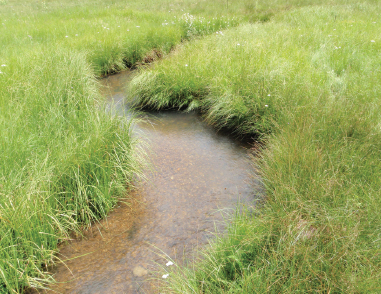
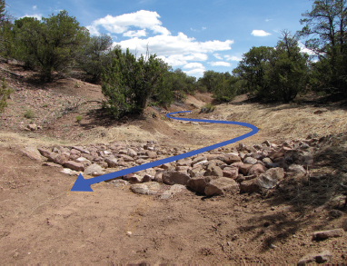
Fig. A1.11. Healthy, meandering waterway during normal bankfull water flow. In flood flows the water flow will beneficially spill over the banks onto the accessible, well-vegetated floodplain. The grasses on the floodplain will help stabilize the soil and harvest sediment, while calming, cleaning, and infiltrating much of the water flow. Credit: Craig Sponholtz
RESPONSE: Floodplains are a water channel’s pressure relief valve. We must maintain the floodplains around channels to allow natural over-bank flood flow and its replenishing effects. We must avoid manmade channelizing, narrowing, or straightening of water channels and their floodplains, which result in channel incision and desiccation of the surrounding land. Do not build a house on a floodplain or an alluvial fan, as addressed below. Utilize land management practices and strategies that enhance water-absorbing ground-cover and hydrate the watershed, not strategies that denude, pave, compact, and dehydrate the watershed.
Incised Channels
PATTERN: An incised channel is one whose bed has eroded to such a depth that excess flow can no longer spread out over the floodplain. The incised channel often continues to cut deeper because large flows that can no longer spill over and diffuse into the floodplain cut downward instead. Water tables then drop because shallow groundwater adjacent to the channel flows into the deep cut and drains away, rather than being replenished by surface water infiltration as occurs in shallow-bedded streams. As water flow level is lowered in the incised channel, the higher capillary zone on the banks, which used to sustain vegetation along the waterway, dries out and disappears. Riparian plants die out and conditions become more arid and fragile as a result.
RESPONSE: Within incised channels use grade-control strategies like one-rock dams to help stop downward erosion, while allowing the channel to cut laterally to widen its banks in a natural meandering pattern. This recreates a floodplain at a lower level within the widening channel, and enables the channel’s flood flows to reconnect with the channel’s new floodplain (fig. A1.10). See Meandering Waterways.
Meandering Waterways
PATTERN: In waterways flowing down gradual slopes (less than 4% slope) the energy of the flowing water tends to be diffused by meandering flow patterns (fig. A1.12). This illustrates the fourth water harvesting principle of slowing, spreading, and infiltrating the water (fig. 1.16B in chapter 1). The more the waterway meanders, the greater the distance water must flow to get from the top to the bottom of the waterway. This reduces the gradient or slope of the bed of the waterway, which reduces the erosive speed of the flow while increasing the duration of flow. The water comes into contact with more of the surface area of the channel bed, allowing more water to infiltrate into the subsurface to recharge wells, springs, and aquifers, and to provide moisture for more plants along the waterway. These plants stabilize the channels and adjacent banks, slow flood flows, catch sediment, build soil, and cool and shelter the water, improving fish habitat and water quality.
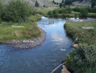
Fig. A1.12. Meandering waterway with easy access to wide, vegetated floodplain. Northern New Mexico. Credit: Craig Sponholtz
RESPONSE: Meandering is good. Let it happen. It is a natural process in which the erosive force of water flow in incised waterways is dissipated as the flow cuts into alternate banks of the channel, inducing the redistribution of bed materials, and the gradual evolution to wider waterways with longer flow paths. In the course of this natural process, constricted channels “heal” themselves over time by creating a widened, healthy floodplain. Although it is outside the scope of this book, a strategy to consider in abnormally straight, eroding channels is “induced meandering,” which speeds up the widening of narrow incised channels and gullies, lengthening the flow path, and making the overall channel depth shallower as it erodes its banks in a natural meandering pattern. See the book Let the Water Do the Work: Induced Meandering, an Evolving Method for Restoring Incised Channels by Bill Zeedyk and Van Clothier for more.
Bank Cutting and Pools
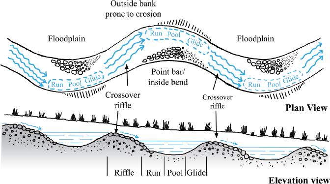
PATTERN: Bank cutting at meander bends occurs where channelized water flowing around a curve cuts the outside bank of the drainage due to the centrifugal force of the water, scouring a basin or pool at the base of the cut. In sandy ephemeral dryland waterways, this pool is hidden when it fills with sand at the end of a runoff event. Bank cutting and pool scouring at meander bends create concave, erosive landforms. The slower moving water on the inside of the curve allows the finer-grained sediment that was cut from the outer bank to deposit on the inside curve, forming a convex depositional point bar where vegetation can get a foothold. Immediately downstream of curves, larger sediment is deposited at the crossover riffles located in the straight runs of the channel between curves. In figure A1.13, notice the more concave slope of the cutting side of the flow. Then notice the convex shape of the deposition side, usually a gently sloping bank.
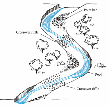
Fig. A1.13. Erosional bank cutting and pools at outer bends, depositional point bars on inside of bends, and depositional crossover riffles between meanders
The undulating bed of the waterway’s lower pools and higher crossover riffles increases the water-holding and water-infiltrating capacity of the waterway, controls flow, and enhances diverse microhabitats— including fish habitat in perennial flows.
RESPONSE: Bank cutting can be very helpful to very harmful depending on the degree of channel incision and relative sinuosity. Where the channel is incised and lacks sinuosity, it can be helpful. Where the channel is not incised and displays appropriate sinuosity, it can be harmful. (See Depositional Bars below for a nonbeneficial example of bank cutting, and the book Let the Water Do the Work for more on assessing the health and sinuosity of a channel.)
Bank cutting on a curve and the location of pools at meander bends can help “spread and infiltrate” water by eventually widening and elongating the flow path in an ever more serpentine/meandering channel. This can reduce the slope of a channel and slow the rate of flow. Typically, you should not attempt to control this curving of a channel. Rather, use your recognition of the curving to correctly place one-rock dams if erosion/grade control within the channel is necessary.
One-rock dams are grade-controlling sediment traps, so place them where sediment naturally accumulates. Straight sections of channels at crossover riffles are the ideal sediment-accumulating locations. Do not place them in curved sections of channels where water would likely cut around the outside edges of one-rock dams. One-rock dams placed at the crossover riffles help raise the elevation of the crossover riffles, while increasing the depth of the upstream pools in relation to the riffles, thereby increasing the water-harvesting potential of the waterway. Note that all crossover riffles within a given channel reach should be raised the same amount of height (if you raise one a foot, raise all the others a foot). Otherwise the slope of that reach of the waterway will be steepened and the flow velocity increased, which would likely increase erosion. See Crossover Riffles for more.
Crossover Riffles
PATTERN: Crossover riffles are the shallow reaches of a channel found in the straight stretches between meander bends and their pools (figs. A1.13, A1.14). Riffles are depositional features formed on the channel bed by large sediment that is scoured out of pools, yet is too heavy to be transported all the way to the next pool. The crossover riffle gets its name because when flowing water is forced to the outside of a meander bend the water must “crossover” the center of the channel on its journey to the outside of the next meander bend. This happens at the crossover riffle location. In the process of crossing over, much of the flow energy needed to transport larger sediment is lost and the material is deposited. This increases the roughness of the channel bed, further slowing the water, and encouraging more deposition.
Fig. A1.14. Crossover riffles are locations where water flow crosses over from one meander bend and its pool to another. Sediment naturally accumulates at these riffles; thus they are perfect locations for sediment-trapping one-rock dams. Adapted from Erosion Control Field Guide and Let the Water Do the Work
RESPONSE: Crossover riffles form naturally and function as grade-control structures in channels. The large-sized sediments that make up the riffle are unlikely to be moved during normal water flow (baseflow) and small floods, yet they are transported and replaced during large floods. The result is a dynamic equilibrium in the depth of the channel bed. Identifying crossover riffles is the most critical step in choosing the correct location to properly construct a long-lasting and effective grade-control structure such as a one-rock dam (fig. A1.14). Crossover riffles are generally easier to locate in channels with well-developed meander patterns and variable-sized sediments. The best way to locate the crossover riffle is to find the approximate midway point between two meander bends that curve in opposite directions. If the meander pattern is poorly defined, or the channel bed is composed of sand, it may be necessary to look for larger sediments that are evenly distributed across the bed of the channel. This subtle clue can indicate the location of the riffle. To make certain this is the case, look for deposits of very fine-grained sediments both upstream and downstream of the probable riffle. These fine-grained sediments often indicate locations where water pooled at the end of a flood, allowing these smaller sediments to settle out.
Grade-control structures like one-rock dams (further described and illustrated in chapter 3) mimic the functions of crossover riffles when they are properly placed between the meander bends in a series. Each one-rock dam should be of a similar height, but no more than one foot (30 cm) tall. Placing one-rock dams at every crossover riffle location may effectively raise the bed elevation of a channel for the entire length of the treated segment. One-rock dams placed as such within an eroded, downcut waterway (depending on the depth of the channel bed) can reconnect the stream with its floodplain—dramatically increasing the amount of moisture and sediment the stream can beneficially cycle through the waterway and its stream-side ecology (fig. A1.15).
Fig. A1.15. A series of one-rock dams just after construction and hydroseeding of banks. Arrow denotes water flow.
Santa Fe Botanical Gardens, Santa Fe, New Mexico. Design by Steve Vrooman of Restoration Ecology. Rock work and photo by Craig Sponholtz. Hydroseeding by San Isidro Permaculture
Depositional Bars
PATTERN: Depositional bars are in-channel sediment deposits formed when relatively slow-moving water drops sediment loads that are too heavy to be moved with the amount of energy available. Depositional bars have a convex shape created by the natural sorting of various-sized sediments. The smallest particles are deposited on the tops of the bars and nearest the banks where water is shallow and moves the slowest. The largest materials are deposited on the edges of the bars where the deepest water has the greatest velocity. There are numerous types of depositional bars, each the product of slightly different hydraulic and sediment transport processes.
Point bars are formed on the inside banks of meander bends and indicate a developing or well-developed meander pattern (see point bars labeled in figures A1.12, A1.13, and A1.14). Lateral bars are formed along banks and can become point bars if they continue to expand toward the opposite bank and create a meander bend. In a relatively straight channel these can indicate the early stages of an evolving meander pattern. Mid-channel bars form in the channel without any contact with adjacent banks and can be an indication of excess sediment that a channel is unable to transport. This type of depositional bar causes the flow in a channel to split around the bar and often leads to unwanted bank erosion. Bank erosion caused by mid-channel bars does not create a stable meander pattern and can be a sign of severe upstream erosion and land degradation.
RESPONSE: Depositional bars of all types are excellent indicators of upstream conditions in the watershed. They show us that sediment eroding from upstream locations is being transported by the stream and deposited farther downstream. A combination of fresh deposition on numerous point bars—typically with little or no plant growth—accompanied by bank erosion on the outside bends, can be a sign that a large volume of sediment is moving down the system. It can also indicate the channel is somewhat incised and has lost floodplain access, and that bank erosion is widening the banks and creating a new floodplain.
The response depends on the type of depositional bars we observe and the overall trend in watershed health affecting the location we are observing. A fairly straight incised channel in which lateral bars are forming can indicate a meander pattern is forming and evolving that will result in natural healing of the incised channel. Lateral bars can be turned into point bars by constructing baffles that erode the opposite bank and encourage the deposition of point bars. (See the book Let the Water Do the Work by Bill Zeedyk and Van Clothier for baffle placement and construction.) This will create more space for a floodplain and accelerate the natural healing process. The presence of mid-channel bars can be a symptom of active degradation and excess sediment production caused by erosion higher in the watershed. In this case it would be desirable to find the location of the erosion that is releasing the sediment and deal with the problem at its source.
Stepped Pools in Steep Drainages
PATTERN: In general, streams with a slope steeper than 4% dissipate energy vertically through step pools as opposed to laterally through meandering and overflow of flood flows into floodplains. The falling-pooling-slowing-falling-pooling-slowing effect of multiple step pools prevents water from attaining extreme speed. Increased channel roughness—created for example by rocks of various sizes protruding from the streambed—can also dissipate stream energy.
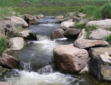
RESPONSE: Stepped pools create a natural pattern that diffuses the energy of steeper flows of water. If you have a steep section of an eroding channel, and rock is available on-site, mimic the stepped-pool pattern (fig. A1.16). Rock-lined plunge pools and one-rock dams can be used to create a series of stepped pools (fig. A1.17).
Fig. A1.16. Step pools constructed by Dr. David Rosgen and associates on a tributary of Three Forks River, Colorado. Reproduced with permission from Let the Water Do the Work by Bill Zeedyk and Van Clothier. Credit: Van Clothier
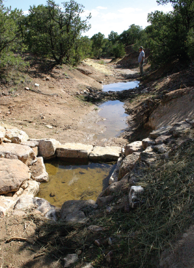
Fig. A1.17. Looking downstream at water pooled within a rock-lined plunge pool, along with pools behind two one-rock dams further downstream. One year after this photo was taken there were abundant native grasses growing through the rock of the structures and in the soils above and below them. Santa Fe Botanical Gardens, Santa Fe, NM. Design by Steve Vrooman of Restoration Ecology. Installation by Craig Sponholtz
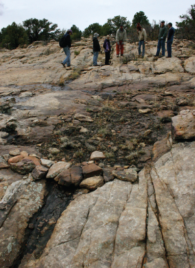
NOTE: If the bed of an ephemeral channel is bedrock, it might be appropriate to create the conditions for an ephemeral spring by constructing well-built one-rock dams or even loose-rock or dry-stacked-rock check dams that are more than one rock high—though this height can weaken the structure. The one-rock dam or a non-wire-wrapped rock check dam can accumulate porous coarse sediments on its upstream side into which water rapidly infiltrates. This water is then slowly released as a seep spring that exits the sediment at the base of the dam. A structure more than one-rock high might be appropriate in this case only because the bedrock can endure the force of water falling over the structure without a scour hole forming that would undermine the dam (figs. A1.18, A1.19). A series of such sediment-accumulating structures could raise the sediment bed throughout the channel and keep the infiltrated water moving downstream below the surface, reducing water loss to evaporation. The ideal location for these structures is typically at the crossover riffle.
Fig. A1.18. A one-rock dam on bedrock, sediment accumulation above, and ephemeral seep below. Northern New Mexico. Work by Craig Sponholtz
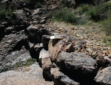
Fig. A1.19. A filter/check dam built atop bedrock by the Civilian Conservation Corps in the 1930s with resulting spring. Note how progressively smaller material, from small rocks to gravel, was placed against the upslope side of the dam’s large rocks to ensure smaller sediment does not erosively wash out between the large rocks. Tucson Mountains west of Tucson, Arizona
Exposed Roots
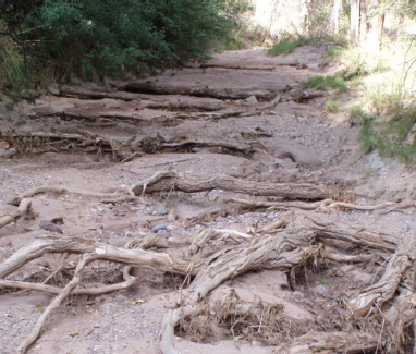
PATTERN: The exposure of tree and shrub roots along large or small drainages (fig. A1.20) indicates significant erosion has occurred. The exposed root crown—the point where the trunk once emerged from the ground and under which the roots began to grow—reveals the original soil level before erosion occurred and exposed the roots. Exposed hammock-shaped roots spreading across the bed of the drainage are telltale tracks of the hammock effect indicating that, prior to erosion, the channel level was above this stabilizing fabric of woven roots growing from the trees on the banks (fig. A1.21).
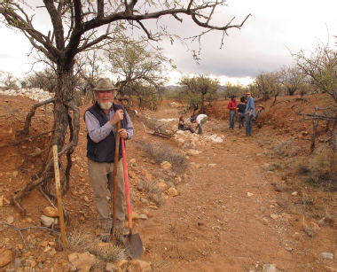
Fig. A1.20. Bill Zeedyk in a severely eroded drainage in southern Arizona. Note the exposed root crown of the mesquite tree just to the left of Bill’s head, and the dangling roots below. A white-colored rock baffle was just constructed where the person is sitting to induce more of a meander into the opposite bank.
Fig. A1.21. Hammock of tree roots exposed in southeast Arizona. Reproduced with permission from Let the Water Do the Work by Bill Zeedyk and Van Clothier. Credit: Van Clothier
RESPONSE: The presence and extent of exposed roots clues you in to the degree of channel and bank erosion occurring in a drainage. What is the nature and composition of the sediment and soil and its resistance to erosion? Is the material somewhat stable clay or less cohesive sand and gravel? The less cohesive and the more erosion-prone the material, the more important the roots of trees and other plants are for stability. If you are seeing the hammock effect in exposed roots, erosion conditions are bad and the need for repair is urgent. Arrest downcutting by constructing grade-control structures such as one-rock dams interwoven among the hammock-like roots and seeded with native grasses to add more root mass.
Look for the cause of the downcutting and address it. If a road crossing has lowered the bed of the drainage, raise the bed again by constructing a grade-control structure such as a one-rock dam on the downslope side of the road. Rock cobble can be used to fill in upgradient of the dam so the raised road surface is hard and drivable in wet conditions. Raise incised channels to reconnect them with their floodplains. If the watershed draining into the channel has lost its cover of perennial vegetation, take steps to bring that sponge-like vegetation back by planting pole cuttings of fast-rooting plants like willow, sod wads, or seeds.
GENERAL PATTERNS OF WATER, SLOPE, AND FLOW
The following patterns are not limited to sheet flow or channel flow alone. They are caused by various flows of water and sediment, the life forms they support, and the slopes they help shape. These patterns also help you read the landscape and its flows. Look for depositional and erosional slopes, high water marks, vegetation, and animal signs. They are described below.
Steep/erosional and gentle/depositional slopes
PATTERN: In landscapes with varied topography— especially undulating hills and valleys—identify these conditions:
• Flatter areas at the tops of hills, where both erosion (loss of soil and sediment) and deposition (gain of soil and sediment) is relatively small
• Steeper slopes, where more soil is lost through erosion than is gained by deposition
• Gentler slopes down hill from steeper slopes, where more sediment is deposited than is lost through erosion
• Transition points, lines, or zones between the areas above
On a micro-level, you may see a gradual slope that is covered with vegetation, organic matter, and silts, which then transitions to a steeper patch of naked sloping dirt, then changes back to a more gradual slope where vegetation, silts, and organic matter again accumulate (fig. A1.22).
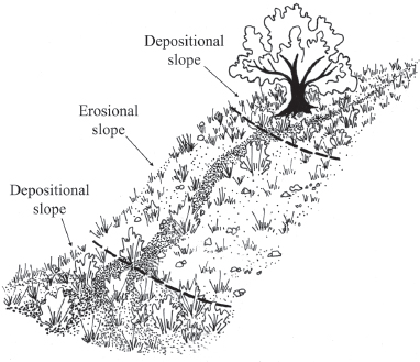
Fig. A1.22. Alternating gradual/depositional slopes and steep/erosional slope
RESPONSE: Areas with gradual slopes could be good locations for planting since they receive water and fertile organic matter and are not degrading. Gradual slopes lower in the landscape tend to have the best conditions for planting since these areas receive runoff from both the gradual and steep-sloped areas above.
On a macro-level, mountaintops and hilltops can transition between steep and more gradual slopes. Steeper slopes with substantial erosion can transition to more gradually-sloping areas where sediments are deposited to form alluvial fans.
Whether you are working at the micro-scale or macro-scale, concentrate water-harvesting and revegetation efforts in gradually sloping depositional areas where less effort is required. Working in a depositional area that is located above a steeper slope could help revegetate the steeper slope below as seed and moisture move downhill. But be very careful hydrating depositional areas located above steep slopes in regions prone to mudslides. In these areas, you may want to focus your water-harvesting efforts exclusively on depositional areas below—not above—steep slopes.
Earthworks such as berm ‘n basins or diversion swales should only be used on depositional slopes where they are easier to build because less soil needs to be moved, they are more stable, and they function more efficiently.
If you are building a small earthen dam or pond, make sure you will not back water up above the gradual/depositional slope. Keeping the water level below the steeper/erosional slopes allows you to direct overflow across gentler, more easily managed gradual/ depositional slopes.
Alluvial Fans
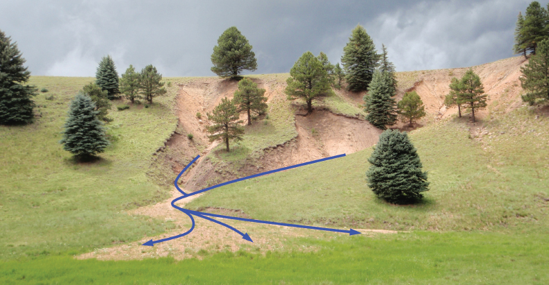
PATTERN: The slopes of tributary channels are always steeper than the slopes of the streams they contribute to. Alluvial fans are depositional landforms created when sediment-laden tributary channels widen and their slope is significantly reduced, such as occurs when channels intersect broad gently sloping valley bottoms. As the water slows and spreads, the heaviest sediments are deposited first. The deposition of the heaviest sediments at the apex (upslope side) of the alluvial fan causes the runoff to slow and spread even more. As the runoff continues to slow and spread, finer and finer sediment sizes are deposited. The result is a broad, convex, fan-shaped landform that is composed of deep alluvial deposits (figures A1.23 and A1.24).
Fig. A1.23. An alluvial fan forming where a steep slope becomes more gradual and flow spreads. Arrows denote water and sediment flow. Credit: Craig Sponholtz
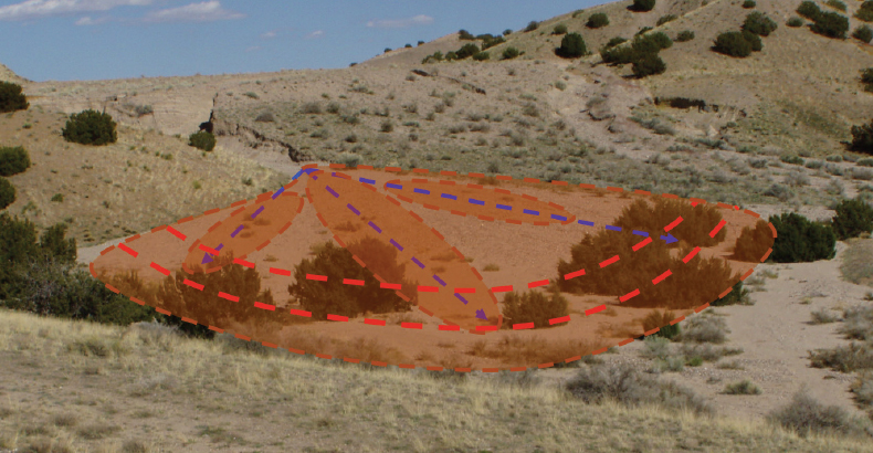
Fig. A1.24. An alluvial fan where steeper, channelized flow spreads out over a more gradual slope. Dotted arrows and shaded ovals denote changing, meandering flow of water and sediment. Dotted arced lines denote contour lines of the fan (same shape as a sheet flow spreader). Credit: Craig Sponholtz
Alluvial fans provide important sediment- and water-harvesting functions in watersheds. They are reservoirs of stored sediment and moisture that buffer the amount of sediment and runoff that downstream channels receive. The natural sediment-sorting mechanism that deposits the largest sediments on the upslope side of the fan and the finest particles on the downslope side creates a soil profile that readily infiltrates large amounts of runoff. Often runoff infiltrates deep into the soil strata, minimizing the availability of surface moisture and consequent evaporation loss. However, the deeply stored moisture and rich alluvial soils create an ideal environment for the growth of deep-rooted plants and trees. Alluvial fans have long been used by indigenous cultures as areas of intense cultivation. The regular input of sediment and nutrient-rich runoff constantly rejuvenates the fertility of the alluvial fan.
RESPONSE: Alluvial fans are created and maintained by the slowing and spreading of regular inputs of sediment-laden runoff water. Alluvial fans with large sediment supplies can be quite steep, but the spreading and slowing of runoff and the resulting deposition of sediment maintain sheet flow despite the relative steepness. Alluvial fans can be fragile landforms since they are composed of loose sediment deposits. Anything that reduces the ability of runoff to slow and spread across the fan will concentrate and accelerate runoff and cause severe erosion and gully formation.
Runoff should be slowed and spread as close to the apex of the fan as possible, especially if there is any gully formation occurring on the fan. The higher upslope the slowing and spreading occurs, the more sediment- and moisture-storage capacity the fan will have. Media lunas (sheet flow spreaders) constructed using rock mulch or brush are ideal to establish and maintain the slowing and spreading of runoff (see figures in the sheet flow spreader section of chapter 3). Alluvial fans dissected by one or more channels will actively erode and degrade. In this case it is important to spread runoff out of each channel as close to the apex of the fan as possible. One-rock dams can be used where the channel is deepest and media lunas can be used where the channel is very shallow. Take care not to concentrate runoff that has been spread out of an actively eroding channel.
Alluvial fans can be constructed in locations where a low-banked channel is transporting excess sediment across a gentle slope. A rock or brush sheet flow spreader can be used to slow and spread runoff onto a relatively broad and flat landform adjacent to the channel. Locate the intended apex of the future fan where the slope and land contours provide the first opportunity to spread runoff out of the shallow channel. A sheet flow spreader constructed at this location will spread and slow the runoff to create sheet flow and assist the sedimentation of the channel. Over time the newly formed sediment deposit will continue to slow and spread runoff to create sheet flow.
High Water Marks
PATTERN: High water marks are the highest points in drainages or floodplains where you can see evidence of past water and sediment flow. Look for lines of discoloration on rocks and vegetation along with snags or accumulations of branches, twigs, grass, and other detritus that indicate the greatest height water reached during flooding. Sometimes these accumulations can be seen surprisingly high on a fence or in the branches of a tree (fig. A1.25).
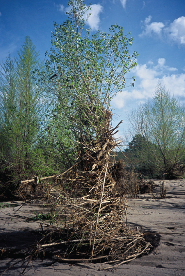
Fig. A1.25. High water flow detritus on young cottonwood tree
RESPONSE: High water marks tell you the potential for future high-water flow events in drainages and floodplains. Do not build within the area of potential flooding, and make sure no high water marks appear above or near the level of your existing buildings’ foundations. If you find evidence of water backing up to a building’s foundation, try to divert and harvest that water with earthworks before it reaches the building. In addition, make sure the grade around the building drains water to a point 10 feet (3 m) away from the building. Flood peaks can become more intense as vegetated, sponge-like land in the watershed is replaced with roofs, streets, and parking lots, or as land is denuded by other disturbances such as overgrazing, overcutting, or excessive all-terrain vehicle use. It is not wise to buy or build a home on flood-prone land, nor to manage the watershed in a way that increases peak flood flows.
Vegetation
PATTERN: Vegetation generally increases in density when more water is present. The presence of different types of plants indicate how long water is available for plant growth—the hydroperiod. Perennial hydric species (hydroriparian vegetation) are long-lived plants that are adapted to waterlogging, and their presence indicates that consistent water supplies are close to land surface. In the Southwest, very high-water-use, broad-leafed cottonwoods (Populus fremontii), sycamore trees (Platanus wrightii), willows (Salix spp.), and cattails (Typha latifolia) typically indicate the presence of springs, perennial water flow, or shallow groundwater. In contrast, hardy triangle-leaf bursage shrubs (Ambrosia deltoidea) are found in well-drained arid upland zones. However, everything is relative. Sometimes even bursage cannot grow in extremely arid zones of the broad landscape, and instead such plants are found along drainages and other areas of greater water concentration. Indicators of increased short-term soil-moisture availability, such as at the bottom of a slope or along with fringes of riparian areas, include the presence of native annuals such as pepper-grass (Lepidium thurberi) and native perennial shrubs such as saltbush (Atriplex spp.) that have grown over-sized compared to their upland counterparts.
RESPONSE: Different plant species are indicators of the timing or duration of soil moisture availability. Familiarize yourself with local plants and their water tolerances and needs. Take note of what grows in association with perennial, intermittent, and ephemeral water flows, and drier uplands. What plants grow in hot, dry, exposed microclimates such as equator-facing slopes? What plants grow on cool, moist, protected slopes on the winter-shade-side of ridgelines? What grows in deep, organic-matter rich soils with high moisture-storing capacity? What grows in shallow, less fertile soils with lower moisture-storing capacity? Plants will tell you how much water is in the soil and are an indicator of what other vegetation types with similar water needs and tolerances can grow in various areas of the landscape. Changes in the number, vigor, and density of plants can also alert you to the improving or declining health of the watershed and its ecosystems.
Animals
PATTERN: Animals, insects, and birds that need readily available water can signify the proximity or dependability of a water source. Dragonflies (Odonata) are found near open bodies of water but are highly mobile. Less mobile, water-dependent indicator species include stoneflies (Plecoptera) and caddisflies (Trichoptera), whose presence often also indicates good water quality. A high number of toads probably indicates a water source that is ephemeral or is too small to support predatory fish.
RESPONSE: Familiarize yourself with the water needs of local animals, insects, and birds. When assessing a site, use direct sightings or other signs of animals, insects, and birds to indicate the nature of local water sources. As with different plant species, the increasing or decreasing numbers and varieties of animals, insects, and birds can alert you to improving or declining health of the watershed and ecosystems. However, in urban settings with artificial fountains and pools, the presence of more water-dependent creatures may not indicate the presence of natural water supplies and healthy watershed conditions.