1
Stress
1.1. Notion of stress
1.1.1. External forces
There are three types of external forces:
- – concentrated forces: this is a force exerted on a point (in Newton units, noted as N). In practice, this force does not actually exist. It is just a model. If we were to apply a force to a point that has zero surface, the contact pressure would be infinite and the deformation of the solid would therefore induce a non-zero contact surface. Nevertheless, it can still be imagined for studying problems with a very concentrated contact type load between balls. The results will thus yield an infinite stress and will need to be interpreted accordingly;
- – surface forces, which will be noted as Fext for the rest of this volume (in Pascal units, it is noted Pa). This type of force includes contact forces between two solids as well as the pressure of a fluid. Practically, any concentrated force can be seen as a surface force distributed onto a small contact surface;
- – volume forces, which will be noted as fv for the rest of this book (in N/m3). Examples of volume forces are forces of gravity, electromagnetic forces, etc.
Incidentally, in this book you will notice that vectors are underlined once and matrices (or tensors of rank 2), which you will come across further on, are underlined twice.
1.1.2. Internal cohesive forces
We wish to study the cohesive forces of the solid S, at point M and which is in equilibrium under the action of external forces. The solid is cut into two parts E1 and E2 by a plane with a normal vector n passing through M. The part E1 is in equilibrium under the action of the external forces on E1 and the cohesive force of E2 on E1.
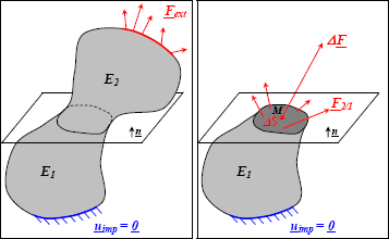
Figure 1.1. Principle of internal cohesive forces. For a color version of this figure, see www.iste.co.uk/bouvet/aeronautical.zip
Let ΔS be the surface around M and ΔF be the cohesive force of 2 on 1 exerting on ΔS, then the stress vector at the point M associated with the facet with a normal vector n is called:
The unit is N/m2 or Pa and we generally use MPa or N/mm2.
Physically, the stress notion is fairly close to the notion of pressure that can be found in everyday life (the unit is even the same!), but as we will see further on, pressure is but only one particular example of stress.
1.1.3. Normal stress, shear stress
We define the different stresses as:
- – normal stress, the projection of σ (M, n) onto n, noted as σ;
- – shear stress, the projection of σ (M, n) onto the plane with normal n, noted as τ.

Figure 1.2. Decomposition of a stress vector. For a color version of this figure, see www.iste.co.uk/bouvet/aeronautical.zip
Thus, σ represents the cohesive forces perpendicular to the facet, meaning the traction/compression, and τ the forces tangential to the facet, meaning the shear. In a physical sense, the pressure found in our everyday lives is simply a normal compression stress.
We then definitely have:
NOTE.– n and t must be unit vectors.
And conversely:
1.2. Properties of the stress vector
1.2.1. Boundary conditions
If n is an external normal, then:

Figure 1.3. External force and associated normal vector. For a color version of this figure, see www.iste.co.uk/bouvet/aeronautical.zip
NOTE.– Fext is in MPa, and a normal external vector is always moving from the matter towards the exterior.
So, Fext can be seen as a stress vector exerted on S, particularly if the surface is a free surface:
These relations are important as they translate the stress boundary conditions on the structure. In order for this to be the solution to the problem (see Chapter 3), these relations are part of a group of conditions that are needed to verify a stress field.
EXAMPLE: TANK UNDER PRESSURE.–
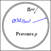
For every point on the internal wall of the tank, we find:
With the external normal vector moving towards the center of the circle, from where the normal and shear stresses are:
Given that the normal stress is negative and the shear stress is zero, the material is subjected to pure compression. The first relation shows that the physical notion of pressure is simply a normal stress of compression: hence the minus sign before the pressure!
1.2.2. Torsor of internal forces
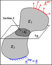
Figure 1.5. Set of internal forces. For a color version of this figure, see www.iste.co.uk/bouvet/aeronautical.zip
The torsor of internal forces of 2 on 1 at G, the center of gravity of S, is:
At first sight, the torsor notion may seem primitive but it enables us to simply consolidate the force with the moment. Should the notion of torsor bother you, you may settle for referring to it in plainer language as force and moment. However, you should not forget that when speaking about internal forces between 2 parts of a solid, it needs to be remembered that there is a force (in N) and a moment (in N.mm). The ambiguity comes from the term “force”, which is used for a force (in the common everyday sense of the word), and as a whole, force + moment!
Let us now seek to link this set of internal forces to the previously discussed stress vector. We then have:
therefore:
These relations are somewhat (or very) complex, but physically, they simply translate the fact that if we add up all of the stress vectors on section S, then we will obtain the force of part E2 on part E1. Lastly, we should not forget that when we add up the stress vectors, we will obtain not only a force, but also a moment (which obviously depends on the point at which it is calculated).
These relations can also be written on an external surface as:
These relations are important because in practice, although we know the resultant Rext/1 or Mext/1, we do not generally know Fext. In fact, an external force is practically applied via the intermediary of a beam, a screed, a jack, etc., and the applied resulting force (or the moment) is known, but the way in which it is divided is unknown.
EXAMPLE: TRACTION–
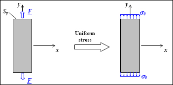
Figure 1.6. Tensile test. For a color version of this figure, see www.iste.co.uk/bouvet/aeronautical.zip
In a tensile test, we know that the resultant of the forces applied to Sy is worth F:
However, in order to deduce that:
we must add a homogeneity hypothesis of the force applied which remains to be verified. Incidentally, we can demonstrate that the two previous integrals are verified with this stress vector.
EXAMPLE: BENDING.–

Figure 1.7. Bending test. For a color version of this figure, see www.iste.co.uk/bouvet/aeronautical.zip
In a pure bending test, we know that the resultant of the forces applied to Sx is worth M.z:
However, by deducing that on Sx:
This formula is a classic example of the mechanics of material which we will discuss (and demonstrate) again when doing the exercises. Should you need to, you can read a more detailed publication, such as [AGA 08, BAM 08, CHE 08, DEL 08, DUP 09], etc.
Obviously, with the moment of inertia:
we must add a linear distribution hypothesis of the stress applied which remains to be verified. Incidentally, we can demonstrate that the two previous integrals are verified with this stress vector.
1.2.3. Reciprocal actions

Figure 1.8. Reciprocal actions. For a color version of this figure, see www.iste.co.uk/bouvet/aeronautical.zip
According to the Law of Reciprocal Action, we have:
Yet:
Hence:
This can be translated by the fact that a fine slice of matter of surface dS, which has a normal vector +n on one side and –n on the other, is at equilibrium under the action of the two opposing forces σ(M, n). dS and σ(M, −n). dS. Evidently, it is very much at equilibrium.
1.2.4. Cauchy reciprocal theorem

Figure 1.9. Stress vectors on the faces of a square. For a color version of this figure, see www.iste.co.uk/bouvet/aeronautical.zip
Let us put this in 2D, in order to make the demonstration easier.
A square is assumed to be infinitely small, therefore the stresses are assumed to be constant everywhere in the cube, hence we have:
In the notation of τxy, the first “x” corresponds to the direction of the facet, meaning the normal vector on the cutting plane in question, and the second index “y” represents the direction of the stress.
The equilibrium equation on the square is written as:
which, for the force equation, induces the following:
This is an automatically verified equation. For the moment equation in M at the center of the square, the below is induced:
where the Cauchy reciprocity theorem is:
It can be shown in the same way in 3D:
EXAMPLE: TORSION OF A WELDED TUBE.–
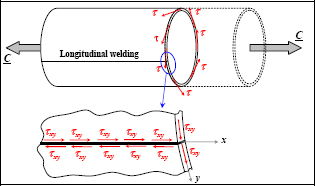
Figure 1.10. Torsion of a welded tube. For a color version of this figure, see www.iste.co.uk/bouvet/aeronautical.zip
A torsion moment is applied to a tube comprised of a rolled and welded sheet. It can be shown (see exercises) that it has been subjected to a homogeneous circumferential shear stress. The Cauchy reciprocity theorem then induces the welding to be stressed by a longitudinal shear τ equal to the circumferential shear stress. All that remains then is the sizing of the welding so that it can withstand this shearing applied force.
1.3. Stress matrix
1.3.1. Notation
There is a stress vector on the facet with the normal vector x:

Figure 1.11. Stress vectors on the faces of a unit cube. For a color version of this figure, see www.iste.co.uk/bouvet/aeronautical.zip
and t can be broken down in accordance with y and z, hence:
Once again, in the notation of τxy, the first index “x” corresponds to the direction of the facet and the second index “y” represents the direction of the stress.
In the same way for the faces of the cube with normal vectors y and z, we have:
 is what is referred to as the stress matrix:
Evidently, the expression of this matrix depends on the coordinate.
Moreover, it is symmetrical in accordance with the reciprocity of the stresses:
The very notion itself of the stress matrix is important, as it assumes that at one point, and in the small volume (REV) surrounding it, the state of the internal forces of matter is entirely represented by this matrix. This is in contrast to the stress vector, which only gives the internal force for one single facet.
EXAMPLE: DRAWING THE STRESSES IN 2D.–
A small square is subjected to a 2D-stress tensor:
These faces are therefore subjected to the following forces:

Figure 1.12. Stress vectors on the faces of a square. For a color version of this figure, see www.iste.co.uk/bouvet/aeronautical.zip
This drawing may be simple, but it is paramount for interpreting the stress tensor.
You obviously would have noticed that the projection of σ(M, x) on y is equal to that of σ(M, y) on x, which is evidently due to the symmetry of the stress tensor.
I will leave it up to you to do the same drawing in 3D.
1.3.2. Invariants of the stress tensor
The stress tensor possesses three elementary invariants. We classically use:
- – The hydrostatic pressure:
It is named thus because when we apply a uniform pressure to a cube in all directions, we obtain:
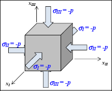
Figure 1.13. Hydrostatic pressure. For a color version of this figure, see www.iste.co.uk/bouvet/aeronautical.zip
In this case, the hydrostatic pressure is evidently equal to the pressure p, in its absolute value.
- – The Von Mises equivalent stress:
With the stress deviator, which is written as:
This stress is very important for estimating the beginning of a ductile material’s plasticity (see Chapters 3 and 4).
- – The determinant:
These invariants are very important for writing the fracture, yield or damage criteria. Given that a criterion of this type is indeed representative of the state of matter, it must not depend on the coordinate at which we write the stress matrix, and therefore it can be written based on these invariants.
1.3.3. Relation between the stress matrix and the stress vector
By constructing the stress matrix, we then have:
And so, irrespective of n:
This relation is very important as it enables the stress matrix to be linked to the stress vector. It will therefore be used very often throughout the rest of this book.
EXAMPLE: TRACTION.–

Figure 1.14. Traction test. For a color version of this figure, see www.iste.co.uk/bouvet/aeronautical.zip
Let us search for the stress tensor of a traction test. The boundary conditions on the six external faces give:
Moreover, if we assume the stresses to be homogeneous:
Hence, the classic result:
Experimentally, during a traction test on a metal sample, we note that the fractography is oriented at 45°. The fracture obviously occurs after significant plasticity. Yet we know that the plasticity is sensitive to the shearing, rather than to the normal stress. Therefore, in order to explain this fractography, we can show that the shearing is maximum at 45°.
This exercise can be done in 2D, or even in 3D, as the demonstration will be similar:
And for a facet with normal n, the normal and shear stresses are:

Figure 1.15. Stress vectors in traction. For a color version of this figure, see www.iste.co.uk/bouvet/aeronautical.zip
where:
So, τ is maximum at 45°.
Calculation using the equilibrium of a triangle of matter:
Knowing that the stress matrix is built on the basis of the equilibrium of a REV, the previous result can be found again by balancing a triangle of matter.

Figure 1.16. Equilibrium of a triangle of matter. For a color version of this figure, see www.iste.co.uk/bouvet/aeronautical.zip
Equilibrium in accordance with x:
Equilibrium according to y:
where:
We then evidently find the previous result again.
1.3.4. Principal stresses and principal directions
As the 3D stress matrix is:
Evidently, this stress matrix can be determined in another coordinate system (x1, y1, z1) by:
with  , the rotation matrix from the basis B to the basis B1, representing the vector coordinates of B1 expressed in the basis B.
EXAMPLE: TRACTION.–
Thanks to this relation, we can evidently find the normal and shear stresses of a traction tensor:
With:
And in the stress matrix expressed in B1, we will recognize the expressions of σnn and σnt.
THEOREM.– There is a direct orthonormal coordinate system (xI, xII, xIII) in which the stress matrix is diagonal:
σI, σII and σIII are called principal stresses and xI, xII and xIII are principal directions (or eigenvectors for mathematicians) associated with σI, σII and σIII respectively.
We then clearly have:
In practice, to determine the principal stresses, it is sufficient to write the below:
which gives three solutions (or two in 2D). Then, to determine the three principal directions, it is sufficient to write the three previous relations. In practice, the three principal directions are orthogonal, so when two of them have been found, the third one can be deduced from the other two.
This can be translated by the following drawing:

Figure 1.17. Principal stresses and associated stress vectors. For a color version of this figure, see www.iste.co.uk/bouvet/aeronautical.zip
The state of the stress as seen by the matter on these two diagrams is the same.
EXAMPLE: SHEARING.–
As the stress tensor is:
So, we will be able to demonstrate that the principal stresses are +τ and –τ, and the principal directions are oriented at +45° and –45°:
On a physical level, this result is easy to understand as we can easily use our hands to feel that the applied force on the left diagram pulls at +45° and compresses at –45°.

Figure 1.18. Stress vectors for pure shearing. For a color version of this figure, see www.iste.co.uk/bouvet/aeronautical.zip
1.4. Equilibrium equation
This exercise is to be done in 2D:
And now, we shall study stress vectors on a small square:

Figure 1.19. Stress vectors on the faces of a square. For a color version of this figure, see www.iste.co.uk/bouvet/aeronautical.zip
This square is subjected to the following stress vectors:
If we assume that the cube is subjected to a volume force fv, then the equilibrium equation in force can be written as:
Hence:
This equation represents the equilibrium equation of the cube.
Using the same approach in 3D leads to:
This equation can also be written as:
This is a fundamental equation as it alone translates the equilibrium of a material point, and therefore also that of the small volume surrounding it. It must therefore be verified at each point of the solid. This is one of the fundamental equations which are needed to verify a stress field (see Chapter 3) in order to be the solution to the problem.
1.5. Mohr’s circle
Mohr’s circle is a graphic method used to rotate the matrix in 2D. It enables us to simply determine the maximum shear stresses, the normal stresses, the principal stresses, the principal directions, etc.
As the 2D stress vector is:
Mohr’s circle is a group of points whose abscissa is a normal stress σ and whose ordinate is the shear stress τ for all the possible facets:
As n is a vector of the plane, then:
with:

Figure 1.20. Mohr’s circle. For a color version of this figure, see www.iste.co.uk/bouvet/aeronautical.zip
The CP vector is thus representative of the facet with normal n, and when n varies, the point P describes a circle with a center C located on the abscissa axis.
It can also be shown that while passing from the vector n to vector u, making an angle θ with n, then an angle 2.θ is made within Mohr’s circle (this incidentally ensures that this angle remains equal to +2.θ, and not to –2.θ, when we take the downwards-facing shearing axis).
Knowing the stress tensor is:
We can then trace the points X (σxx, τxy) and Y (σyy, –τxy), and trace the center C and Mohr’s circle. From this, we can therefore deduce the main stresses σI and σII and the principal directions.

Figure 1.21. Mohr’s circle. For a color version of this figure, see www.iste.co.uk/bouvet/aeronautical.zip
From Mohr’s circle, we can also deduce that the maximum normal stress is either σI or σII and that the maximum shearing τmax is equal to:
This relation can moreover be generalized in 3D:
We can also show that in 2D:
EXAMPLE: TRACTION.–
The stress tensor in traction is:

Figure 1.22. Stress vectors on a facet with a normal vector n in traction. For a color version of this figure, see www.iste.co.uk/bouvet/aeronautical.zip
Mohr’s circle can then be traced:
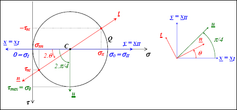
Figure 1.23. Mohr’s circle in traction. For a color version of this figure, see www.iste.co.uk/bouvet/aeronautical.zip
We then find:
The maximum shearing at 45° is equal to σ0.


