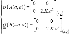
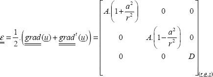
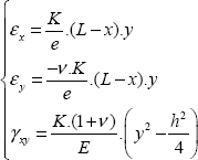
10
Solutions to Exercises
10.1. Rosette analysis
QUESTION 1.–
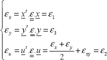
We can simply say that the unit strain in any direction amounts to:
Writing this relationship for x, for y and for vector u at 45° of x (without forgetting to take the unit vector u, i.e. u  and removing reference to point M to streamline the notation):
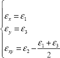
So, we obtain:

That is:
QUESTION 2.–
We have to begin by writing that the external forces applied are zero, and that the external normal direction is equal to z:
which is:
and the stress tensor is consequently plane for on any free surface:
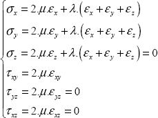
We then use the behavior law between stress and strain, assuming the material linear elastic, homogeneous and isotropic:
where we can calculate the Lamé parameters using the Young modulus and the Poisson ratio by:
So, we obtain:
Accordingly, the third relationship allows us to determine Ɛz:
note that we never see plane stress and plane strain at the same time (except when both stress and strain are zero, as may be expected!).
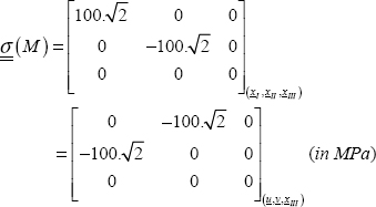
So, we obtain (this is the answer to the next question):
and
QUESTION 3.–
See above.
QUESTION 4.–
To determine the principal stresses, we must solve:
This equation admits three solutions, the three principal stresses σi (i = I, II and III). We then determine the principal directions by:
Here there is evidently an obvious solution:
Then we can now work in 2D, which should lead us to:
Unless you have inverted the two principal stresses, which of course amounts to the same (the order of the three principal stresses is of no importance and we often class them in ascending order, though this is by no means necessary).
You can now determine xI using the relationship between the principal stress and principal direction:
For example, by using xI(a,b) (while still using 2D), we obtain two relationships between a and b, which in fact are the same relationship. Of course, this stems from the fact that det  Accordingly, these two coefficients depend on an undetermined multiplicative coefficient; in fact, only the direction of this vector is of interest: its norm is of no importance. For example, we can take:
Here, we may note that this vector is not normalized; it is not difficult to normalize it, but to do so would be pointless!
In fact, this vector x1 is clearly 3D, but its coordinate in relation to z is 0 since the problem is plane:
We also arrive at this result by recalling that the three principal directions are necessarily orthogonal, and as here, the third principal direction is equal to z, the other two directions are necessarily in the plane (x, y).
We can now continue with the same reasoning for the last principal direction, or simply use the fact that the principal directions are orthogonal between one another, which here for instance would be (you can easily check that this is indeed the case):
You can now recall the pattern of principal stresses (in 2D) and verify that the angle between x and xI is here 10.5°.
QUESTION 5.–
We can show that the maximum normal stress (for all possible facets) is necessarily the maximum of the three principal stresses, here:
And so the direction of the normal vector of this facet is the associated principal direction, here xI.
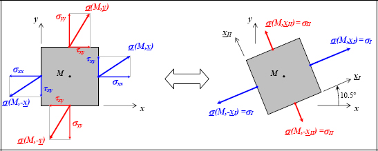
Figure 10.2. Stress vector and principal stresses. For a color version of this figure, see www.iste.co.uk/bouvet/aeronautical.zip
QUESTION 6.–
If we consider the material brittle, we can use the normal stress criterion:
which is not verified here, and consequently there would be failure (in practice, stress increases progressively from 0 and failure is reached when the criterion is reached for the first time).
The direction of the crack created by this would be perpendicular to the facet direction of the maximum normal stress, here the facet with normal vector xI, and would consequently be in the plane (xII, xIII).
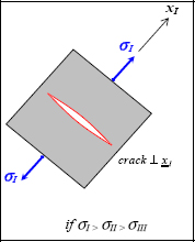
Figure 10.3. Tension failure of a brittle material. For a color version of this figure, see www.iste.co.uk/bouvet/aeronautical.zip
QUESTION 7.–
We can show that the maximum shear stress is the maximum between half the difference of the principal stresses:
And the direction of the associated facet is in the plane (xI, xII) oriented at 45° of xI or of xII. Indeed, we can show that the shear stress of a facet of normal vector (xI + xII) is in direction of (xII − xI) and that it remains the same as that of a facet of normal vector (xII – xI) (which is in direction of (xI + xII)).
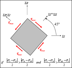
Figure 10.4. Maximum shear. For a color version of this figure, see www.iste.co.uk/bouvet/aeronautical.zip
QUESTION 8.–
The Von Mises stress is here:
QUESTION 9.–
If we consider the Tresca criterion:
This criterion is not verified and consequently there will be plasticity.
Considering the Von Mises criterion:
This criterion is verified and so there will be no plasticity.
In conclusion, identifying plasticity is dependent on whether it is the Tresca or Von Mises plasticity criterion that is best adapted to your material.
In practice, since there is little difference between these two criteria, deciding between them can be difficult as the experimental dispersions are often of the same order as the difference between the two criteria.
Further application:
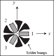
We find:
and:
It is clear then that the principal coordinate system is (x, y, z) and the three principal stresses are the three diagonal stresses.
Accordingly, the failure criterion in maximum normal stress:
is not verified, so there is failure with a crack in the plane (x, z).
The Tresca criterion:
is not verified; so there is plasticity.
The Von Mises criterion:
is not verified; so there is plasticity.
10.2. Pure shear
We must simply determine the principal stresses of the stress tensor:
And observe that in the plane (xI, xII), by performing a 45° rotation around xIII, we obtain a state of pure shear:
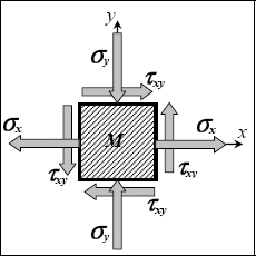
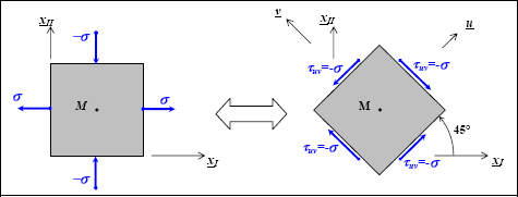
Figure 10.7. Stress vectors and maximum shear. For a color version of this figure, see www.iste.co.uk/bouvet/aeronautical.zip
10.3. Compression of an elastic solid
QUESTION 1.–
To find a solution to this problem, we must determine the displacement, stress and strain fields, verifying:
- – the equilibrium equation;
- – the relationship between displacement and strain;
- – the behavior law linking stress and strain;
- – the displacement and stress boundary conditions.

In addition, as we know that the solution exists and is unique, we just need to find one, and if it meets all of these conditions, it is the right one!
In this case, it seems reasonable to search the displacement field in the form:
In other words, the displacement field is in the z-direction and is function only of z. Again, we do not need to justify this choice, since if it allows us to meet all the conditions then it is the (one and only) solution.
We can then determine the strain tensor:
With the conventional notation:
We then determine the stress tensor:
The equilibrium equation  then leads to:
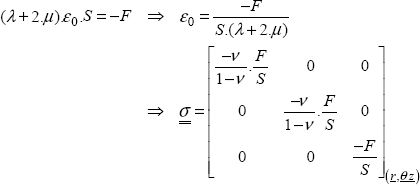
where ε0 is a constant (equal to strain εz, hence this notation). We can then redetermine the stress tensor:
We must then verify the stress boundary conditions:

This equation announces the fact that the sum of stress vectors on the top side in z = h is equal to –F.z.
Hence, by replacing the stress tensor by its expression:
And here noting that:
We can now determine the displacement field:
The boundary conditions then give:

Now that all of these conditions have been verified, this is consequently the one and only solution here.
QUESTION 2.–
Piston displacement is the displacement in z = h:
QUESTION 3.–
Here, we should note that:
where ν → –1 corresponds to the case where the shear modulus tends to infinity:
And v = 0.5 corresponds to an incompressible material. Indeed, we should recall that in tension:
And the volume variation is consequently zero irrespective of the stress value:
In this case, we also observe that if ν = 0.5, then the piston displacement will be zero irrespective of the force applied. This is a logical result since if the material is incompressible then its volume will not change during compression and piston displacement will remain null.
In practice, some materials, such as rubber for example, do indeed behave in a quasi-incompressible behavior.
10.4. Gravity dam
QUESTION 1.–
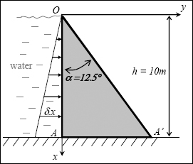
Water pressure increases in a linear manner with depth, expressed by the well-known Bernoulli equation:
except that here z is noted as x, due to x is the vertical axis! At point O, pressure is equal to atmospheric pressure, but this pressure is not taken into account since only pressure greater than this atmospheric pressure acts on the structure. So we have:
where ρ is the volumic mass of the water (and not that of the concrete, which we note as ρc). Load δ.x is indeed in N/m2 and is a surfacic loading.
QUESTION 2.–
Let us assume the stress tensor is a linear function of x and y:
We can begin by asking what justifies this choice. In practice, we see that all loads are linear and all edges of the structure are straight. Of course, this does not prove that the solution is in this form, but since we know that if we indeed find a stress, strain and displacement fields that meet all the conditions, then it is the one and only solution. We must simply make the choice and verify that this choice meets all the conditions, nothing else is needed! The conditions here are:
- – the equilibrium equation;
- – the relationship between strain and displacement;
- – the behavior law linking stress and strain;
- – the displacement and stress boundary conditions;
- – the compatibility condition.
Indeed, from the moment we make a hypothesis concerning stress (or strain), we must not neglect the compatibility condition. Remember, this condition allows us to both ensure that strain can be integrated and to determine displacement. Essentially, as you perform the hypothesis for the six functions (in 3D, or three in 2D) assuming a shape for the stress (or strain) tensor and that there are only three (in 3D, or two in 2D) for the displacement field, it is by no means clear that everything will be coherent.
The compatibility condition is written as follows:
In practice, we have to determine strain according to stress then check that this equation is indeed verified. Here, this is evident since the compatibility equation only applies for second derivatives. Indeed, since stress is a linear function of x and y, strain will be as well (there is a linear relationship between stress and strain), and all of the secondary derivatives will be zero.
Now we will write out the equilibrium equation:
where  is the volume force due to gravity, that is:
where ρc is the density of concrete. So, now we have  in N/m3, which is the force per unit of volume that applies throughout the structure (unlike an external surface force, as in the case of stress boundary conditions which are only applicable on an external surface).
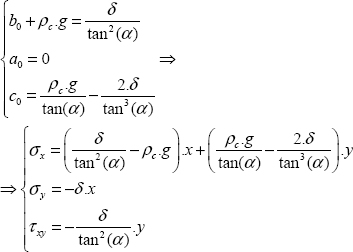
Consequently, the equilibrium equation gives:
So, we can now rewrite the stress as follows:
Now we will write the stress boundary conditions for the side in contact with the water:
hence:
We should note here that for the function (a.x + b) to be zero for any value of x, it must necessarily be the case that a and b are also zero.
Accordingly, the stress boundary conditions for the inclined side in contact with air (note that the equation for this line is y = x.tan(α) and the external normal vector is 
hence:
Hence the numerical application:
In practice, we must still show that displacement is zero at the lower part of the dam (in x = h). To this end, we have to determine strain, integrate this strain to determine displacement, then verify that it is zero in x = h. You can perform these calculations yourselves, but if you complete them, you will see that it does not work! In conclusion, we do not have the exact solution here, and to find it, we have to use a much more complex stress field! However, the solution that we have found here remains a good approximate solution to the real problem.
QUESTION 3.–
To determine whether the dam breaks, we have to use a failure criterion adapted to the dam’s concrete. Since concrete is a brittle material, we adapt a criterion of the maximum/minimum principal stress:
Next, we must simply determine the principal stresses at any point of the dam then determine their maximum/minimum values. Since these stresses are linear, by merely looking at the end values, we know that the maximum will be one of these points:
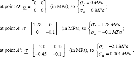
Accordingly, the failure criterion is verified throughout the structure. It is at point A that we are closest to failure. If water pressure increases (or if the failure criterion of the concrete decreases, due to aging for instance), failure will occur when σI reaches the tension failure stress that is 2.5 MPa. Furthermore, the crack will occur perpendicularly to xI (here xI = x). In practice, we can avoid failure by fitting concrete reinforcing bars in the x-direction at point A; such concrete reinforcing bars would of course be set in a concrete base in the ground.
Here we should note that concrete is a highly asymmetrical material whose compression resistance is around 10 times more than its tension resistance. In other words, we must use concrete mainly for compression and avoid putting it under tension. Typically, we use reinforcing bars in order to alleviate this, or for still greater resistance we can use pre-stressed concrete. For this, iron or steel rods are placed under tension then the concrete is poured around them. Once the concrete is dry, this tensile force on the metal rods is released, which then compresses the concrete. So, even when pre-stressed concrete is put under tension (within a certain threshold) it remains in compression (with its metal rods in tension)!
10.5. Shear modulus
QUESTION 1.–
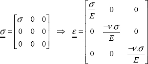
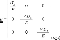
In order to determine strain from stress, we simply use the behavior law:
Hence the classic result under tension:
So, the material is elongated according to the tension x-direction and shortens in the two perpendicular directions.

QUESTION 2.–
As above:
QUESTION 3.–
We simply use the strain from questions 1 and 2:
QUESTION 4.–
If σy = –σx, then:
QUESTION 5.–
In order to determine the stress and strain tensor in (u, v), we simply perform a 45° rotation relative to z.
where  is the rotation matrix (and here, of course, with θ = 45°):
Hence:
Conventional result illustrated by:

Figure 10.11. Stress vectors and maximum shear. For a color version of this figure, see www.iste.co.uk/bouvet/aeronautical.zipEssentially, in the coordinate system (u,v,z) we have:
Again as for stress, we perform a rotation of the strain tensor:
Essentially, in the coordinate system (u, v, z) we have:
And by definition of the shear modulus G, we have:
So, we have:
10.6. Modulus of a composite
QUESTION 1.–
If we assume that both materials show the same strain, then we have:
where index f corresponds to fibers, index r to resin and  to mean strain.

This amounts to a parallel consideration of the two materials:

Figure 10.13. Parallel and serial homogenization models
Accordingly, the total stress is the sum of the stresses for the two materials (not forgetting to account for the fiber volume fraction Vḟ, while that of resin is of course 1–Vf):
If we consider an elastic behavior for the two materials:
Then we find that the mean modulus is the mean of the two moduli:
QUESTION 2.–
Assuming that the two materials show the same stress, then we have:
This amounts to a serial consideration of the two materials (see Figure 10.13).
Accordingly, the total strain is the sum of the strains for the two materials (not forgetting to account for the fiber and resin volume fraction):
Thus, we obtain the mean modulus:
QUESTION 3.–
Which hypothesis seems the more reasonable depends on the direction of tension: if we pull in the fiber direction (x), the parallel model seems better, but if we pull in the transversal direction to the fibers (y or z), the serial model seems better. Moreover, this is what we observe through experimentation.
QUESTION 4.–
If we plot the mean modulus, then we obtain the results in Figure 10.14.
The modulus that we obtain, assuming homogeneous stress, is called the Voigt limit and the one obtained assuming homogeneous strain is called the Reuss limit. We can show that the Voigt model constitutes an upper bound and the Reuss’ model a lower bound. In practice, we obtain values between these two: approaching the Voigt limit for tension in the fiber direction and approaching the Reuss’ limit for particulate reinforced composite.

Figure 10.14. Young’s modulus according to parallel and serial homogenization models. For a color version of this figure, see www.iste.co.uk/bouvet/aeronautical.zip
10.7. Torsional cylinder
QUESTION 1.–
The displacement of point M(r, θ, z) is equal to the product of the radius by the angle of rotation:

QUESTION 2.–
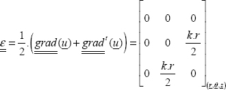
We can determine the strain tensor by:
Be careful to use the gradient tensor in cylindrical coordinates for this relationship.
QUESTION 3.–
We can begin by observing that 0 is a principal strain and that r is the associated principal direction:
Now we just have to work on the plane (θ, z) before determining the two principal strains and the associated principal directions. You will then find:

Figure 10.16. Principal coordinate system. For a color version of this figure, see www.iste.co.uk/bouvet/aeronautical.zip
QUESTION 4.–
Volume expansion (more generally known as volume variation) is equal to the trace of the strain tensor:
Since the trace is an invariant of the tensor, you can show that the result is the same irrespective of the coordinate system that you use for the calculation. In particular, here you can perform the calculation in (r, θ, z) or in (xI, xII, xIII).
Here we find that there is no volume variation. Since the displacement consists of the rotation of disks piled on top of each other, it is logical that the volume variation is zero.
In reality, we do see that the volume variation of a torsional cylinder is zero, but only at the first order. Indeed, we can show that there is a shortening of the cylinder but only at the second order. Since we perform all of the calculations here at the first order (in particular the relationship between the strain tensor and the displacement field gradient), we find no shortening and no volume variation.
QUESTION 5.–
The stress tensor is:
We then simply write out that the moment of the stress vector on the top side is equal to the applied torque:
where A is the center of the top side. With:
Hence:
And here we find the conventional relationship of strength of materials:
where I0 is the quadratic moment of inertia of a circular torsional beam:
QUESTION 6.–
For the stress, strain and displacement fields to be the solution here, they must verify:
- – The equilibrium equation:
You can verify that the divergence of the stress tensor is zero (not forgetting to take the divergence expression in cylindrical coordinates, noting that the volumic force is zero here).
- – The relationship between stress and strain:
This relationship is clearly verified; moreover, this is how we determined the strain tensor according to the displacement field.
- – The behavior law linking stress and strain:
This relationship is clearly verified; moreover, this is how we determined the stress tensor from the strain tensor.
- – The stress and displacement boundary conditions:
The displacement boundary condition is the clamping of the lower side:
This relationship is verified automatically on seeing the shape of the displacement field selected.
The stress boundary conditions are divided in two, first for the lateral side, then for the top side:
For the lateral side, there is no external force, so we have:
This relationship is verified.
On the top side, the sum of the applied forces is a torque C in the z-direction. Nonetheless, we must not forget to prove that the force is indeed zero:
The second relationship is true since it has been used previously to determine the k coefficient. As for the first relationship, you can easily show that it is true by calculation or simply sketch the stress vectors on the top side for visual evidence that the result is clear (upon adding all the arrows, we clearly find 0, on the other hand if we add their moments at point A we find torque C).

Figure 10.17. Torsion stress. For a color version of this figure, see www.iste.co.uk/bouvet/aeronautical.zip
QUESTION 7.–
We should begin by choosing a failure criterion adapted to a brittle material. The conventional criterion is that of maximum/minimum normal stress:
So we should start by determining the principal stresses, then find where they are maximum/minimum (and in what facet direction). Here, we can easily show that the principal stresses and directions are:
We clearly see that the principal stress directions are the same as those for strain. This remains the case so long as the material is orthotropic (i.e. if the material has three perpendicular symmetry planes); which is particularly the case of an isotropic material for which all the planes are symmetrical!
Accordingly, the principal stresses are maximum/minimum where r is maximum, so here in r = R. Since a brittle material typically corresponds to greater resistance in compression than in tension (which is particularly the case of chalk, concrete, composite, glass, etc.), the criterion will be reached in r = R and for a facet direction xII and the crack will be perpendicular to xII. This crack will be shaped like a screw with a 45° angle to z (test this with a piece of chalk; a quick test beats a long explanation). Failure will be reached when the criterion is reached, that is:
Hence:
QUESTION 8.–
We need to use the material to the maximum of its potential throughout the structure in order to decrease cylinder mass. In this example, we see that the material at the center of the cylinder is almost completely unnecessary. We should instead use a hollow cylinder with the greatest possible diameter (typically, this diameter is limited by the size of the structure and by the technical characteristics of its production). Where Ri and Re are the internal and external diameters, we can show that:
And where e = Re–Ri is the thickness of a hollow cylinder, assuming it to be small compared to Re (allowing for a first-order limited development), we find:
And since cylinder mass is proportional to R.e (at the first order):
where ρ is the density and L is the cylinder length. Accordingly, we should minimize the R.e ratio while keeping the R2.e ratio constant (as we may assume that C and σtrac are provided). The radius must then be maximum in order to minimize mass:
10.8. Plastic compression
QUESTION 1.–
We see that stress tends to minus infinity when cube thickness tends to 0, but only if we write the behavior law with engineering stress/strain! Here, the law is written in true stress/strain. Between the true and engineering stress/strain, we have the relationship (see Chapter 7):
where index t corresponds “true” and no index to “engineering”. You will also see that I have omitted index t from the text of this exercise, as often happens in practice (and to push you to think!).

Figure 10.18. Plastic compression. For a color version of this figure, see www.iste.co.uk/bouvet/aeronautical.zip
If we plot this engineering stress/strain curve again, we obtain:

Figure 10.19. True and engineering stress/strain tension curves. For a color version of this figure, see www.iste.co.uk/bouvet/aeronautical.zip
As can be seen here, the elastic part of the curve is almost invisible when plotted to scale (for a 70 GPa modulus and an elastic limit of 400 MPa, the elastic strain limit is 0.00057).
Under compression, we see that if compression is continued indefinitely, then we obtain:
While under tension, if we continue tension indefinitely, then we obtain:
The force/displacement curve that you obtain will consequently be the same as the engineering stress/strain curve (except the cross-section for force and to the length for displacement).
QUESTION 2.–
In reality, when we perform a compression test, we obtain a barrel effect:
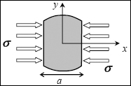
This effect is due to friction between the sample and the machine grips preventing the material from straining in the directions perpendicular to force (due to the Poisson effect). In practice, such barrel effect is very difficult to avoid, so we must do as much as possible to reduce the friction coefficient (even adding rollers to allow the material to strain freely, although this is an awkward procedure and can significantly disturb the stress field).
The solution of using a longer sample, as we do for tension, is clearly the wrong solution, since it leads to sample buckling!
QUESTION 3.–
If we perform a bi-compression test:

We obtain the start of plasticity at the same stress as in pure tension. Indeed, if the material is ductile, then we can assume that its elasticity limit is correctly represented by Von Mises criterion:
And we find that the Von Mises stress is equal to the absolute value of σ, as with tension/compression.
QUESTION 4.–
One solution for performing this test consists of using beams to press on the cube. This experimental device allows us to limit barrel effect by leaving the material to strain freely during compression. In practice, this amounts to designing an orthotropic material with high longitudinal rigidity (relative to the beams’ compression rigidity) compared to transversal rigidity, which is much lower (relative to beams’ bending rigidity).
QUESTION 5.–
When performing a tri-compression test, plasticity is never reached (in theory at least!):
Indeed, we obtain zero Von Mises stress and never reach plasticity irrespective of the value of σ. This stems from the fact that plasticity is insensitive to hydrostatic pressure.
This does not mean that strain will be zero, since if plastic strain is zero, elastic strain will not be (and you can determine this strain).
10.9. Bi-material beam tension
Part 1: pure tension
QUESTION 1.–
With the beam under tension, it is logical to search for stress in both materials in a state of pure tension. Of course, this explanation is by no means a demonstration, but since we are aware that there is only one solution to this problem then if the proposed solution verifies all conditions (equilibrium equation, displacement and stress boundary conditions, compatibility condition, stress/strain relationship, displacement/stress relationship), it is certainly the correct solution.

QUESTION 2.–
We write that the sum of the stress vectors on the side with the equation x = L is equal to F:
For this calculation, we have to break down the integral on material 1 and material 2:
Hence:
QUESTION 3.–
Assuming that the material is linear elastic, homogeneous and isotropic, we find:
QUESTION 4.–
If the materials are bonded at y = 0, then elongations in the x-direction, that is Ɛx must be equal (we will return to this condition later), so:
Hence:
Accordingly, strain must be continuous at the bonding point, whereas stress is discontinuous:

Figure 10.23. Stress and strain through bi-material tension. For a color version of this figure, see www.iste.co.uk/bouvet/aeronautical.zip
However, in reality this stress discontinuity does not occur. Stress can go from stress 1 to stress 2 over a very short distance, over the bonding interface between the two materials for instance. This bonding interface is particularly solicited, indeed, we can show that in large part this is due to τxy shear stress. Moreover, if this τxy shear stress is too great it will lead to the glue failure.
QUESTION 5.–
Since the stress and strain fields in materials 1 and 2 are different, we must find different displacement fields for both materials; u1 for material 1 and u2 for material 2. We will start with u1 (u1, v1):
By integrating the first two equations, we find:
where f(y) and g(x) are two unknown functions to be determined. Reinsert this into the third equation, and we find:
Indeed, if two functions dependent on two different variables are equal, then they must be constant.
Hence:
In order to determine these three constants, we must use the boundary conditions. In practice, the u0 vector (ct2, ct3) represents a translation of a rigid-body displacement field and ct1 a rotation around z. You can show this result by determining the displacement field induced by this rotation:
By:
Essentially, any of the displacement fields equal to a rigid-body displacement field can be a solution here. In other words, if a displacement field is a solution, then adding the rigid-body displacement field changes nothing, since its derivative, and then the strain field, remains the same.
In this instance, since:
Then:
And going through the same process for material 2, we find:
And here we see that the two displacement fields are equal. In the general case, we ought to show that the displacement fields are equal at the bonding interface (as is the case here) but not necessarily everywhere.
QUESTION 6.–
We must start by defining what the mean modulus is. Suppose I had given you the bi-material without saying that it is made of two different materials, and asked you to determine its Young’s modulus. You would then have performed a tension test, determining stress by  and strain by
  (where the
  notation indicates mean of x), then plotting the stress curve according to strain. The slope of this curve would have been the mean modulus. So, here:
In passing, we find that the mean stress is the mean of the two stresses and that the strains are all the same.
Hence the mean Young’s modulus, which here is clearly equal to the mean of Young’s moduli:
QUESTION 7.–
On review, we see that the stress, strain and displacement fields are almost the solution to this problem:
- – the equilibrium equation is verified (I will leave you to do the calculation, but since the stress field is constant);
- – the stress/strain relationship is verified;
- – the strain/displacement relationship is verified;
- – the displacement boundary conditions are verified (at x = 0);
- – the bonding interface conditions at y = 0 are verified.
To be more precise, we should verify that the displacement fields of both materials are equal at the bonding interface, as is the case here. You should also note that this condition leads to strains in the x-direction being equal as well (which is only true since the bond is in the x-direction).
We should also verify that the stress vectors for the bonding plane facets are equal for both materials (otherwise the bonding interface would not be in equilibrium!). This is indicated here by  which is verified.
The stress boundary conditions are almost verified. Indeed, you can show that in y = ±h, the stress vector is equal to external force (which is zero here).
We must then show that the sum of the stress vectors on the force application side (in x = L) is equal to F. As a result, this relationship is verified (it is the relationship that we used to determine stress):
However, we have not verified the moment equation. Here the problem becomes more challenging. Clearly, if we apply force at the middle of the side (at x = L and y = 0), it will not work:
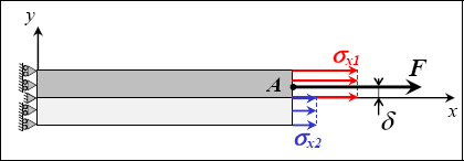
Figure 10.24. Stress at the end of a bi-material beam under tension. For a color version of this figure, see www.iste.co.uk/bouvet/aeronautical.zip
So, the force F must necessarily be moved by a distance δ for there to be in equilibrium. We can determine this distance by writing that the moment is zero at this point:
Then:
Hence:
If, in addition, we take E1 = 3.E2, then we find δ = h/4.
In conclusion, if you can apply force at point A, then this will indeed be the solution here. In practice, this is done by restraining the rotation around z at the machine grip, and then generating a moment (which is equivalent to displacing the force application point):
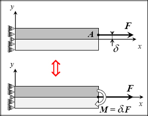
Figure 10.25. Bi-material beam tension test. For a color version of this figure, see www.iste.co.uk/bouvet/aeronautical.zip
If we now apply F right in the middle (at y = 0), the solution above is no longer the solution to this problem, and you have to continue the exercise!
Part 2: tension/bending
QUESTION 8.–
Now we need to apply F at exactly the point where y = 0.
Here, the different rigidity of the two materials will induce bending moment in the beam in the z-direction:

Figure 10.26. Strain during bi-material tension/bending. For a color version of this figure, see www.iste.co.uk/bouvet/aeronautical.zip
In physical terms, this is quite easy to understand: if material 1 is more rigid than material 2, i.e. more difficult to strain, then it will be less strained than material 2 (nature obeys the law of least effort, as do students, though perhaps not if you have come this far!).
So, we can assume that the strain field will be a bending strain field:
So, we have:
You can then write that force at x = L is F:
hence:
And that moment at x = L and y = 0 is zero:
hence:
And finally:
which gives a rather complex stress field:
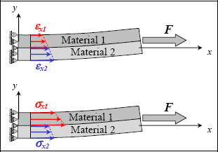
Figure 10.27. Stress and strain during bi-material tension/bending. For a color version of this figure, see www.iste.co.uk/bouvet/aeronautical.zip
So, strain is continuous through the thickness (and with linear variation), while strain is discontinuous at the bonding interface (and with linear variation).
I will leave you to show that all of these conditions are verified and that this is indeed the solution here.
10.10. Beam thermal expansion
Part 1: Mono-material beam
QUESTION 1.–
If the beam is assumed to be constrained at both ends, then the strain field in the x-direction will be zero (there will be no displacement in the x-direction) and we can assume that the strain field will be in the form of a pure tension strain field (with γxy = 0 in particular):

However, at the end of the exercise we must remember to show that all of the conditions were met and that we do indeed have the solution here.
The stress field will also be one of pure tension:
The thermal strain field will be that due to thermal expansion:
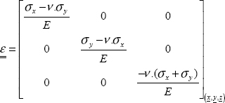
Finally, the behavior relationship leads to:
Hence:
The elongation in the y-direction is positive due to thermal expansion, and stress in the x-direction is a compressive stress due to impeded expansion (essentially, the material would have expanded, but since it has been prevented from doing so, compression appears instead).
You can verify that the stress and strain fields proposed are indeed the solution here.
QUESTION 2.–
If we assume the beam is free, then the stress field will be zero:
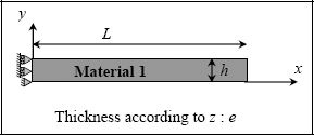
The thermal strain field will be that due to thermal expansion:
finally, the behavior relationship leads to:
In conclusion, the material needs to dilate, so we leave it to dilate, and doing so it does not generate stress.
Again, you can verify that the stress and strain fields proposed are indeed the solution here.
Part 2: bi-material beam
QUESTION 3.–
For total strain, we have:

Figure 10.30. Thermal expansion of a constrained bi-material beam
And for stress:
So, the thermal strain field is that due to thermal expansion:
Having applied the behavior law in both materials, we have:
In conclusion, there is no difference to the case of a single material; the two materials act as they would without interaction! This is due to the fact that the bonding conditions (displacements and stress vectors have to be equal at the bonding interface) are verified with the stress and strain fields of a single material.
QUESTION 4.–
The problem is more complex in the case of the free beam.

In this case, if you follow the same logic as above, you should find:
But the bonding condition is not verified here! Indeed, if the strains in the x-direction were different for the two materials, then the elongation of the bonding interface would be different for both, leading to the bond’s failure!
In reality, the difference in thermal expansion coefficients for the two materials induces bending in the beam:
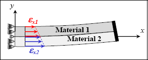
Figure 10.32. Strain due to thermal expansion of a free bi-material beam. For a color version of this figure, see www.iste.co.uk/bouvet/aeronautical.zip
So, we can take these strain fields in the form:
Once again, this is not a demonstration; you should ultimately show that with this strain field all of the problem’s conditions are verified and that your solution is indeed the solution here.
And we still have:
where stresses in the x-direction are a priori functions of y.
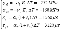
So, having applied the behavior law in both materials:
Hence:
We must then write that the force and moment at the end of the beam is zero:
- – in x = L and at point A (L,0):
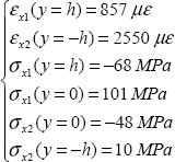
So you have two equations and two unknowns (a and b), hence:
Accordingly, strain is continuous through the thickness (and with linear variation) while stress is discontinuous at the bonding interface (and with linear variation):
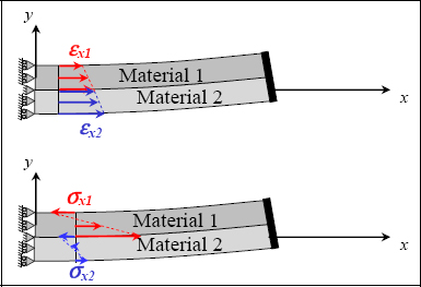
Figure 10.33. Stress and strain field due to thermal expansion of a free bi-material beam. For a color version of this figure, see www.iste.co.uk/bouvet/aeronautical.zip
In order to verify your calculations, you can show that:
Once again, you can verify that the stress and strain fields proposed are indeed the solution here.
10.11. Cube under shear stress
QUESTION 1.–
By writing that the sum of moments is zero (at point O for instance), you will find:

QUESTION 2.–
We take:
For this tensor to be the solution here, we must verify:
- – the equilibrium equation. I will leave you to verify that the divergence of this tensor is indeed zero;
- – stress boundary conditions:
- - in
 which is indeed verified;
 - - in y = a :

- - in
where the point C is the center of the side with equation y = a. These conditions mean that the sum of all the stress vectors on this side must be equal to the applied force (in force and in moment).
Hence:
We can show that the second equation is verified automatically, and that the other two lead to the same result, thus allowing us to determine K according to force F:
You can show that the stress boundary conditions in y = −a lead to the same result (the problem is symmetrical!).
We must then determine the strain tensor, integrating it to determine the displacement field, then show that the displacement boundary conditions are verified. The problem here is not entirely explicit, and these conditions are not provided, which is not too significant since here we are mostly interested in the stress field.
And we must verify that the proposed stress field indeed verified the compatibility condition:
I leave you to verify that this is indeed the case here.
QUESTION 3.–
Plotting stress vectors on the external faces allow us to understand how the material is strained and to image the stress boundary conditions (here M induces σy and F induces τxy):

Figure 10.35. Stress vectors on a cube under shear stress. For a color version of this figure, see www.iste.co.uk/bouvet/aeronautical.zip
QUESTION 4.–
Since the material is brittle, we can use a maximum/minimum normal stress criterion (remember that the maximum/minimum normal stress is necessarily one of the three principal stresses):
Since here the problem is 2D, we clearly have 0 as the third principal stress and z the associated principal direction.
We must then determine the other two principal stresses, so here:
You can show that these two expressions are maximum/minimum at the four corners of the square. We must simply study the stress state at these four points; and even at the two top points due to the problem’s symmetry:
Since brittle materials typically have tensile stress less than that of compression (in absolute value), failure will occur at point A, with the crack developing in the perpendicular direction to y.
Failure will occur when the failure criterion is reached, so:
QUESTION 5.–
If the material is ductile, we can use the Tresca criterion (which is a criterion for the start of plasticity rather than a failure criterion!):
Here, we obtain:
And we can show that this criterion is maximum at A, B and C (and at the three symmetrical points with y negative) for:
So plasticity will begin at the same time at the three points A, B and C (and at three symmetrical points with y negative). In the case of a ductile material, plasticity will then spread outwards from these six points but without leading to failure (at least not immediately).
10.12. Spherical reservoir under pressure
QUESTION 1.–
A priori the displacement field should be in the form:

Since this problem is spherically symmetric, it is not a function of θ and φ (the displacement value must be the same irrespective of the value of θ and φ) and displacement is necessarily in the r-direction (if at one point we had displacement in the φ, since the plane (O,r,θ) is the problem’s plane of symmetry, then this displacement is necessarily zero; the same applies for displacement in the θ-direction).
Hence:
QUESTION 2.–
The problem’s boundary conditions are simply stress boundary conditions on the inside and outside of the sphere:
- – in
 essentially, pressure inside the sphere is P and is in the r-direction.
 - – in
 essentially, pressure outside the sphere is zero.
QUESTION 3.–
Navier’s equation corresponds to an equilibrium equation in which we add the relationship between displacement and strain:
and the behavior law between stress and strain, which for a linear elastic, homogeneous and isotropic material is here:
Here, the only equation that is not zero is that in the r-direction (of course, remember to determine the Laplacian gradient or divergence operators in spherical coordinates):
Since λ + 2.μ is not zero, we find a second-order differential equation. So, the solution is the linear combination of two linearly independent solutions. Here, we can search for solutions in the form rn. And we find:
So we find that the characteristic polynomial solutions are n = 1 and n = −2, hence the solution:
where A and B are two constants to be determined.
QUESTION 4.–
The strain tensor is:
QUESTION 5.–
And the stress tensor:
QUESTION 6.–
The stress boundary conditions give us:
Hence:
QUESTION 7.–
The volume variation is:
Since A > 0, the volume variation is strictly positive, and volume increases.
QUESTION 8.–
If e/R is small compared with unity, we can then perform a first-order limited development (remember,  So, we obtain:
This is a very conventional result that you can also find by writing the equilibrium equation of a half sphere (see the last question).
QUESTION 9.–
If the material is ductile, then we can use the Tresca criterion (which is a criterion for the start of plasticity rather than a rupture criterion!):
Since the stress tensor is diagonal here, we have the principal stress immediately. We obtain:
For a mass of:
QUESTION 10.–
A carbon/epoxy-type composite material is a brittle material. So, we use a maximum/minimum normal stress criterion:
Here, all of the stresses are positive, hence:
For a mass of:
Hence, a structure around three times lighter in carbon/epoxy composite fabric. In reality, this type of reservoir is indeed made of composite material.
QUESTION 11.–
In order to verify the hypothesis in question 8, we must calculate:
This ratio is less than one and the hypothesis is verified.
QUESTION 12.–
We have to write out the equilibrium of a half sphere. On the one hand, it is subjected to the force of pressure. So, you must integrate this pressure (the direction of which varies) or use the result stating that this integral is equal to the pressure multiplied by the projected surface, which here is P.π.R2. On the other hand, it is subjected to the force due to the stress σθ (which we can assume to be constant since the thickness e is less than R), which here is 2.π.R. σθ By equating the two terms, you will get the previous result.

Figure 10.37. Stress in a reservoir under pressure. For a color version of this figure, see www.iste.co.uk/bouvet/aeronautical.zip
10.13. Plastic bending
QUESTION 1.–
If you recall the beam theory or using the results of exercise 17, we can show that when bending:
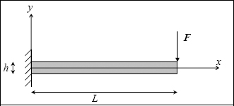
where Mfz is the bending moment, here:
and Iz the quadratic moment of inertia of the cross-section (here rectangular):
We obtain the classic result of a linear stress function of x and y, which is maximum at the clamping point:

Figure 10.39. Stress in a beam under elastic bending. For a color version of this figure, see www.iste.co.uk/bouvet/aeronautical.zip
We should also show that there is a quadratic shear stress τxy, null at the top and bottom of the cross-section, which is negligible compared to the longitudinal stress σx in the case of a full cross-section (see exercise 17). This shear stress is to be disregarded in this exercise.
Clearly, the strain field is in the same form as the stress field (εx = σx/E).
You can also find the result for the stress field by writing that the integral of σx on a cross-section is equal to the cohesive force. Cohesive force is of course made up of a shear force Ty = F and a bending moment Mfz = −F.(L–x). If you integrate the moment created by σx in a cross-section, you will find the K(x) expression directly. And if you integrate the force created by σx on a cross-section, then you will find zero (it is easy to see graphically in the figure above that the sum of all the red arrows is zero)! In order to find the shear force, we must integrate τxy which is quadratic, but is neglected here. This point is treated in detail in exercise 17 concerning the bending beam.
QUESTION 2.–
Plasticity will appear at the place where stress is maximum. The term stress is clearly insufficient, as typically it concerns a 3D stress tensor. Since the material is ductile (aluminum), here we assume that it follows a Von Mises criterion:
Here, the Von Mises criterion is equal (in absolute value) to σx:
Plasticity will begin at x = 0 and y = ±h/2, for a force Fe such that:
QUESTION 3.–
Once plasticity has occurred, it spreads through the beam from these points. We cannot use the distribution of linear stress function of y to determine these zones, as we did earlier, since the stress will saturate at σx = σe while strain εx will remain linear with y at the same time:
In order to determine the plasticity zone, we have to write that the bending moment (which is always equal to –F.(L–x)) is equal to the integral of the moment created by this stress distribution (not neglecting to write that σx is linear at the center then equal to σe):
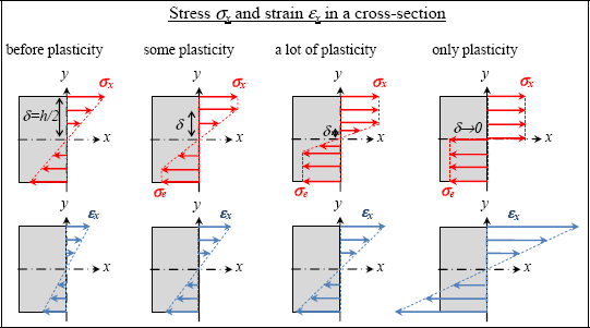
Figure 10.40. Stress and strain in an elastic–plastic bending beam. For a color version of this figure, see www.iste.co.uk/bouvet/aeronautical.zip
In this way we can determine δ that depends on x and F, then plot the plastic zone’s development:

Figure 10.41. Plastic zone in an elastic–plastic bending beam. For a color version of this figure, see www.iste.co.uk/bouvet/aeronautical.zip
We can then calculate the maximum force Fmax that can possibly be applied to the beam. This maximum force corresponds to cases in which the whole cross-section of the beam (here in x = 0) is plastic (δ → 0):
So, we obtain Fmax = 1.5. Fe. According to the deflection d, the force curve will be linear up to Fe, then becomes nonlinear, and becoming asymptotic towards Fmax:

Figure 10.42. Plastic behavior of an elastic–plastic bending beam. For a color version of this figure, see www.iste.co.uk/bouvet/aeronautical.zip
QUESTION 4.–
If we release the force at point A having reached plasticity, we discharge along the same slope as the initial slope, observing a plastic strain of the beam dp (see previous figure).
So, having released force F, we obtain a stress field in the cross-section with a zero:
That is a stress field in the form:

Figure 10.43. Stress in an elastic–plastic bending beam. For a color version of this figure, see www.iste.co.uk/bouvet/aeronautical.zip
Indeed, we see that the most loaded points (at y = ±h/2) are those with the greatest plastic strain and will consequently generate negative stress when the loading is released.
10.14. Disc under radial tension
Part 1: conventional method
QUESTION 1.–
Since the disc is thin, we can consider it as being the object of plane stress (while a thick disc would be the object of plane strain instead). Moreover, the problem presents a central symmetry at center O, so τrθ = 0, hence:
So, we have strain in the form:

Remember that we cannot have plane stress and plane strain at the same time.
QUESTION 2.–
A priori the displacement field should have the form:
But since the problem is centrally symmetric, it is not function of θ (the displacement value must be the same irrespective of the value of θ) and displacement in the θ-direction is necessarily zero (if at one point we had displacement in the θ-direction, since the plane (O,r,z) is the problem’s plane of symmetry, then this displacement would necessarily be zero).
Hence:
The last conditions are the most difficult to justify (u is not function of z and w is not function of r), and moreover we will see below that there are only approximations.
If we assume stress is homogeneous through the thickness, then so is strain. So, displacement u will also not be function of z. The fact that we then assume that εrz = 0 necessarily implies w is not function of r (I leave you to write the displacement gradient) and we find ∂w / ∂r = 0, so we can assume:
And using the Navier’s equation:
We then find:
which then provides the resolution:
where A, B, C and D are the integration constants.
QUESTION 3.–
We must then write the boundary conditions in order to determine the integration constants. The displacement boundary conditions require a radial displacement of zero in the interior radius and a z-displacement of zero on one side of the disc (for example in z = 0):
In this way you determine B and C, hence:
We can now determine strain:
In addition, to respect the plane stress hypothesis, we must have:
Hence:
Now for stress:
Now we must write the stress boundary condition in r = b to determine the A constant:
hence:
So, after numerical application:
Of course, you can see that the σr(b) = P boundary condition is indeed verified.
The state of maximum stress (meaning the maximum normal stress, i.e. in cases where the material is assumed to be brittle) is reached in r = a for a facet of normal vector er; so if a crack should develop, it would be in the plane (θ, z).
Part 2: energy-based method
QUESTION 4.–
The easiest choice of displacement field is to take a linear field function of r:
This choice allows us to respect the null displacement in r = a.
Remember that the Ritz method allows us to determine the best (in terms of the difference between strain energy and work of external forces, which would be zero if we had the exact solution) function of those proposed. So if your proposed functions are pertinent, you will find a pertinent solution, otherwise you will only find the “least ill-adapted” of the functions you proposed!
In this choice of displacement field, we can see that stress is not plane:
Indeed:
For them to be plane, we must make a broader choice of displacement field, for example:
And by imposing a condition on B’, we would have plane stress.
QUESTION 5.–
We must then determine the strain energy:
This rather trying calculation gives us:
QUESTION 6.–
We must then calculate the work of the external forces. Here, this work is created in r = b throughout the disc periphery (by applying pressure P, the displacement u(b) is induced):
QUESTION 7.–
Now we just write that (Ed–Wext) is minimum for the best value of A’, so:
which after the calculation gives:
QUESTION 8.–
Then we obtain the following numerical calculation:
Note that the σr(b) = P boundary condition is not verified. This is typical for an energy-based method; the only boundary conditions respected are those imposed in the choice of the field imposed (here the chosen displacement field imposes u(a) = 0).
We see a significant difference in the displacement field: 6.35.10−2 mm for the conventional method compared to 4.69.10−2 mm for the energy-based method.
In reality, much of this difference is due to the hypothesis of plane stress. Indeed, if you repeated the first part of this exercise choosing the hypothesis of plane strain (hypothesis adapted for thick disk), you would have found:
And:
Hence, there is a displacement in r = b of 0.047 mm, which is in keeping with the energy-based method.
10.15. Bending beam: resolution by the Ritz method
QUESTION 1.–
To ensure that the solution reached using the Ritz method is pertinent, we must respect the boundary conditions as much as possible. Here, we must have null displacement in x = 0 and in x = L, hence the displacement field (choosing a sinusoidal function) of the beam’s neutral fiber:
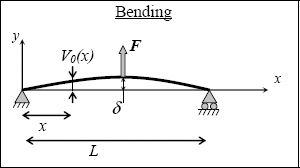
Draw this function to convince yourself that the form is indeed coherent with the required form.
QUESTION 2.–
The previous function allows us to determine the neutral fiber’s displacement. Of course, we also need the full displacement field in order to determine the strain field, then the stress field, before applying the Ritz method. To this end, we have to assume that a straight cross-section remains straight and perpendicular to the neutral fiber after deformation. We should also note that the rotation angle of a cross-section is, at the first order, equal to the derivation of function ν0.
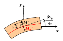
Figure 10.46. Kinematic of a bending beam. For a color version of this figure, see www.iste.co.uk/bouvet/aeronautical.zip
Hence:
You can also note that if we assume a small angle of rotation, the displacement in the y-direction at all points of a cross-section is assumed to be the same.
QUESTION 3.–
The strain field is then:
And at a first approximation, the bending only generates a strain Ɛx. We will consider this again for the next question.
QUESTION 4.–
The stress field is then:
So, we obtain a σx stress field conforming to a bending stress field:

Figure 10.47. Stress in a simply supported bending beam. For a color version of this figure, see www.iste.co.uk/bouvet/aeronautical.zip
On the other hand, the stress field σy is wrong (so I will not ask you to plot it). We also find a null τxy shear stress field, which, in reality, is not the case. Indeed, we can show that the equilibrium equation imposes a parabolic τxy field, null on top and under the beam and maximum at the center (see exercise 17 for more details).
QUESTION 5.–
We can then determine the strain energy:
where IZ is the quadratic moment of inertia of the cross-section:
Next, we must determine the work of the external forces. Here supporting forces do not work (as there is null displacement) and only the force in the beam center works:
Now we only have to write that (Ed–Wext) is minimum for the best value of δ, so:
which gives:
We can compare this result to the exact result (that you can show by recalling the lesson on beams or by reading [AGA 08] for instance):
Here, noting that:
And you find yourself comparing:
If ν = 0, the first coefficient is 48.7, and the result of the energy-based method is of very good quality. On the other hand, if ν = 0.3, the coefficient is 65.6 and the result is incorrect! Indeed, here it is not the energy-based method that is in error but the hypothesis on the form of the stress/strain tensor. The hypothesis used for the displacement field requires that the only non-zero strain tensor components εx and consequently the three diagonal terms of the stress tensor are non-zero. In reality, we see the opposite: only the σx term of the stress tensor is non-zero, and the three diagonal terms of the strain tensor stem from this. Had we taken this hypothesis, we would have found σx = E.εx and so:
which is a very good result compared to the exact beam solution (or nearly exact, as even this beam solution is also an approximate solution).
10.16. Stress concentration in open hole
So:

Figure 10.48. Open hole tension test. For a color version of this figure, see www.iste.co.uk/bouvet/aeronautical.zip
And:
QUESTION 1.–
To show that this stress field is the solution here, we have to show that it verifies all of the problem’s conditions such as:
- – The equilibrium equation. You can indeed show that:
Since the volume forces are zero. Do not forget to write the divergence in cylindrical coordinates!
- – The stress boundary conditions:
- - At the hole, that is, in ρ = 1, the external forces are zero, hence:
You can therefore show that this relationship is true.
- - At infinity, that is, when ρ → +∞, the external forces are zero for a facet of normal vector y and equal to σ0.x for a facet of normal vector x:
You can show that these relationships are indeed verified. You can perform the calculations in cylindrical or Cartesian coordinates, but when you compare or multiply the magnitudes (vectors or tensors); they must all be in the same coordinate system!
For example, you can start by showing that:
We can then determine the strain field, and then verify that the strain field does verify the compatibility condition. Then we can finally integrate this strain field to determine the displacement field. In practice, we can show that the compatibility condition is not totally satisfied and that the proposed solution is not the exact solution (but that it is a good approximation). Since this compatibility condition is not totally satisfied, we cannot integrate the strain field to determine the displacement field; at least not in 3D (although in 2D, we can show that it is possible).
In conclusion, the proposed stress field is a good approximation of the solution, but it is not the exact solution here.
QUESTION 2.–
The only component of the non-zero stress in r = R is σθ:

Figure 10.49. Stress field around a hole. For a color version of this figure, see www.iste.co.uk/bouvet/aeronautical.zip
QUESTION 3.–
The stress concentration factor at the edge of the hole is clearly reached at the edge of the hole, i.e. at r = R, and is:
- – Kt = 3 in tension:
This is a conventional result worth retaining: when you make a hole of small size compared with the surrounding structure (for example, located far from surrounding holes, which is seldom the case), then the stress factor at the edge is 3! In other words, the fact that the hole is small divides the structure’s strength by 3. Indeed, this result is true for a brittle material but not for a ductile material. For the ductile material, the stress concentration at the hole edge leads to localized plasticity that smooths the stress distribution at the hole edge, thereby decreasing the stress concentration (contrary to the received notion that it must be avoided at any cost, plasticity can in fact have a positive effect on a structure’s strength). We can even show that this result does not apply to brittle materials that can damage themselves, such as the composite material used in aeronautical structures (a unidirectional laminate, for instance, with carbon fibers and epoxy resin). In this case, the damage (in terms of matrix cracks, delamination and localized fiber failure) plays the same role as plasticity and decreases the stress concentration due to damage (contrary to the received notion that it must be avoided at any cost, damage can in fact have a positive effect on a structure’s strength).
Furthermore, if we reach structural failure, since σθ is the only non-zero stress the crack propagates in the (r, z) plane, beginning at r = R and θ = π/2, so at the top of the hole (x = 0 and y = R) as we could well expect.
- – Kt = 1 in compression:
In fact, the curve above is more complex than it appears! We observe a stress concentration of 3. This result is true in tension as well as in compression. In other words, if you apply tension, you will see a tension stress three times greater than the imposed tension, and if you apply compression, you will see a compression stress three times greater than the imposed compression. But at the same time, you will see compression of the same value as the stress applied (in absolute value and in r = R and θ = 0) during a tension test, and tension of the same value as the applied stress (in absolute value and in r = R and θ = 0) during a compression test. This is a much less intuitive result than the previous one.
So, if you are working with a ductile material for which the elasticity limits for tension and compression are of the same order, then the start of plasticity will be at r = R and θ = π/2 and with a Kt of 3, both in tension and in compression. But if you are working with a brittle material for with the failure limit under tension is much less than the compression limit (in absolute value), then in tension you will reach failure at r = R and 0 = π/2 with a Kt of 3, but in compression you will reach failure at r = R and τ = 0 with a Kt of 1!
10.17. Bending beam
Part 1: stress tensor
QUESTION 1.–
We must isolate the right part of the beam:
where G is the center of gravity for the cross-section S(x) in question. Hence the torsor of the internal forces of the right part on the left part is:

And the only force on the right part is the force F, which we must move to G, hence:
The shear force Ty will induce τxy stress (stress in the y-direction for a facet of normal vector x) and the bending moment Mz will induce the normal stress σx (stress in the x-direction for a facet of normal vector x).
QUESTION 2.–
The stress tensor has to verify the equilibrium equation (here without volume force):
It must also verify the compatibility condition written in stress via the behavior law (to ensure that once the strain tensor is determined, it can be integrated to determine displacement):
It must also verify the stress boundary conditions (here written in 2D):
- – on the top side:

- – on the bottom side:

- – on the right side of the beam:

where G (L, 0) is the center of gravity of the right side of the beam. Of course, we cannot assume that stress is homogeneous on this side, indeed, below we will show that this is not the case!
It must also verify the displacement boundary condition. Essentially, it has to determine the strain tensor by means of the behavior law:
then integrate to determine the displacements:
and verify that the displacement field verifies:
Considering the hypotheses made for the form of the stress tensor, we can then verify that this boundary condition is not totally verified!
QUESTION 3.–
The equilibrium equation provides:
So, assuming the form of σx proposed:
where f and g are two functions of x to be determined.
We then write the boundary conditions on the top and bottom sides:
Hence:
And:
And, writing the boundary condition on the right side of the beam:
We then obtain the value of K according to F:
And we can show that the second boundary condition on this side is verified automatically:
QUESTION 4.–
The form of σx is linear function of y, so we have compression (as K<<0) in the top section and tension in the lower section; since the linear form is clearly the simplest function to verify this. In addition, σx is linear function of x, as bending moment. And σx is zero at right side of the beam and maximum in x = 0, as bending moment.

Figure 10.51. Stress in a bending beam. For a color version of this figure, see www.iste.co.uk/bouvet/aeronautical.zip
QUESTION 5.–
We plot σx and τxy for any cross-section of x-coordinate:

Figure 10.52. Stress in a bending beam. For a color version of this figure, see www.iste.co.uk/bouvet/aeronautical.zip
We see σx linear function of y, maximum below and minimum on top and a parabolic τxy zero on top and below, and maximum at the center. The σx stress is clearly in the x-direction (facet of normal vector x) and the τxy stress is clearly in the y-direction (facet of normal vector x), even if their parabolic distribution is difficult to make clear, hence the dotted curve drawn in x (however, this does not mean that this stress is in the x-direction!).
Then we calculate the resultant of the stress:
And the moment:
Of course, this calculation is much like that performed for the boundary condition in x = L.
Clearly, we have found the torsor of internal forces determined in question 1.
QUESTION 6.–
Aluminum is a ductile material. Accordingly, we must choose the Von Mises criterion (or the Tresca criterion):
Now we must calculate this Von Mises stress and, crucially, determine where it is maximum:
Note that here we are in 2D and with σy = 0, hence the simplified expression for Von Mises stress, but this is clearly not generally true.
Under the root we have the total of two positive terms, so this total is maximum at x = L and is:
Under the root we have the total of three positive terms (as L > h), so this total is maximum at y = ±h/2 and is:
Essentially, the maximum Von Mises criterion is reached at two points with coordinate (0, ±h/2) and is of the value above.
QUESTION 7.–
So at the criterion limit, we obtain:
Hence:
Once this criterion is reached, the beam will begin to develop plasticity at the two points (0, ±h/2). If we exceed this value, then we will obtain plastic strain and an irreversible deformation of the beam. Indeed, the Von Mises criterion is a criterion for the start of plasticity rather than a failure criterion!
QUESTION 8.–
Glass is a brittle material, so we must choose the criterion of maximum normal stress:
There remains but to calculate the maximum principal stress and above all where it is maximum:
Note that here we are in 2D and with σy = 0, hence the simplified expression for principal stresses, but this is clearly generally not true. We can also verify in passing that if σx = 0 we indeed find the two principal stresses ±τxy and if τxy = 0 that we indeed find the two principal stresses σx and 0.
Under the root we have the total of two positive terms, so this total is maximum at x = L, and, considering that y can have the same positive and negative values, the maximum is obtained for y < 0 (since K < 0):
Hence:
Under the root we have the total of three positive terms (since L > h), so this total is maximum at y = −h/2 (since y < 0) and is:
Essentially, the criterion of maximum normal stress is reached at point (0, −h/2) and is of the value above.
QUESTION 9.–
So, at the criterion limit, we obtain:
Hence:
Once this criterion is reached, the beam will begin to break at point (0, −h/2). Indeed, the criterion of maximum normal stress is a failure criterion! In addition, at the point where τxy = 0, we will see a crack propagate perpendicular to σx and in the y-direction.
Part 2: strain tensor and displacement
QUESTION 10.–
Assuming the material is linear elastic, homogeneous and isotropic, we have:
Hence:
QUESTION 11.–
If ν = 0:
Then we must integrate the relationship linking strain to displacement:
Hence:
where f(y) and g(x) are the two functions to determine. The last equation is the sum of terms function only of x and of other terms function only of y, hence:
where ct1 is a constant, hence:
And by writing these three boundary conditions, we have:
QUESTION 12.–
Effectively, we see that the data of these three boundary conditions lets us determine all of the integration constants ct1, ct2 and ct3. Of course, it is not by chance, boundary conditions must prevent all rigid body displacement fields that are in 2D, two translations (in the x and y-directions) and one rotation (in the z-direction). And we observe that the first two boundary conditions prevent translations by clamping the point (0, 0) and the third preventing rotation around this point.
QUESTION 13.–
The deflection is defined as the displacement in the y-direction of point (L, 0), so that:
Hence, if L >> h:
NOTE: we obtain K = −1.92 N/m4
Part 3: finite elements comparison
NOTE ON UNITS.– In a calculations code by finite elements, any unit can be chosen but, we must simply use coherent units. We typically use mm and N, so the unit for stress is MPa.
QUESTION 14.–
Concerning displacements:
If L << h (here we have L/h = 20), we obtain:
We do have zero v at clamping point and maximum at x = L. The numerical application gives a deflection of 3.2 mm. And we verify that v is not function of y.
We have u that is much less than v (at the first order according to the previous relationship), zero at the clamping point and maximum at x = L. And we verify that it is linear function of y and that its maximum value is reached at (L, h/2) and is 0.12 mm, and its minimum value is reached at (L, −h/2) and is -0.12 mm.
Concerning σx:
We have zero σx at x = L and at y = 0, and linear function of y and of x. The numerical application gives a maximum value of 480 MPa at (0, −h/2) and minimum of −480 MPa at (0, h/2). We obtain 485 MPa numerically, but you must not forget that the calculated stress only applies far from the boundary conditions (Saint Venant’s principle), since the maximum value is indeed reached at a boundary condition! Unfortunately, this is often the case!
Concerning σy:
According to our calculations, we have zero σy everywhere! But again, our calculations are only applicable far from the boundary conditions (Saint Venant’s principle) where this stress is effectively low. In addition, in the calculation by finite elements, displacements have been imposed as zero where the material is clamped, which is not verified by our analytical model where we impose:
We can show that by rigorously imposing zero displacements at the clamping point creates σy stress, but the analytical calculation is then much more complex.
Concerning τxy:
We can verify that τxy is maximum at y = 0, zero at y = ±h/2 and not function of x, of course with the exception at the boundary conditions (Saint Venant’s principle). The numerical application provides a maximum value of 6.0 MPa, which is almost verified, given that the scale is adapted to disturbances met at the boundary conditions.
Concerning σvonMises:
We obtain a Von Mises stress almost equal to the absolute value of σx (since τxy is negligible). We can analytically obtain a maximum value of 480 MPa. This value is reached at (0, ±h/2), as obtained analytically.
In practice, we can show that to size a bending beam we must size it to σx. This only applies if it is indeed a beam, i.e. if L >> h and if the cross-section is full. Indeed, for hollow beams, tubes for instance, shear stress cannot be disregarded.
Concerning Max(σI, σII):
We obtain a maximum principal stress almost equal to the positive value of σx (since τxy is negligible). We can analytically obtain a maximum value of 480 MPa. This value is reached at (0, ± h/2), as obtained analytically.
Concerning Min(σI, σII):
We obtain a minimum principal stress almost equal to the negative value of σx (since τxy is negligible). We can analytically obtain a minimum value of −480 MPa. This value is reached at (0, h/2).

